Hayward SwimClear C7030 Owner's manual
- Category
- Above ground pool accessories
- Type
- Owner's manual

ISC2031 REV B
SwimClear™
Owner’s Manual
Models C2030 C3030 C4030 C5030 C7030
TOP MANIFOLD CARTRIDGE FILTERS
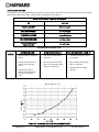
MODEL EFFECTIVE FILTRATION RATE DESIGN FLOW RATE
Residential Commercial
FT2 M
2 GPM LPM
C2030 225 20.9 84 318
C3030 325 30.2 122 462
C4030 425 39.5 150 568
C5030 525 48.8 150 568
C7030 680 63.2 150 568
MAXIMUM WORKING PRESSURE FOR ALL MODELS 50 PSI (3.45 BAR)
ATTENTION INSTALLER: THIS MANUAL CONTAINS IMPORTANT INFORMATION ON THE OPERATION, AND
SAFE USE OF THIS EQUIPMENT.
THIS MANUAL IS INTENDED FOR THE END USER OF THIS PRODUCT
Hayward Pool Products
620 Division Street, Elizabeth, NJ 07207
Phone: (908) 351.5400
www.haywardnet.com

USE ONLY HAYWARD GENUINE REPLACEMENT PARTS
Page 2 of 12 SWIMCLEAR™ CARTRIDGE FILTER ISC2031 REV B
READ, UNDERSTAND, AND FOLLOW ALL SAFETY AND OPERATION INSTRUCTIONS.
FAILURE TO FOLLOW SAFETY AND OPERATION INSTRUCTIONS CAN RESULT IN SEVERE PERSONAL INJURY
OR DEATH.
CAUTION To reduce risk of injury, do not permit children to use or climb on this product. Closely
supervise children at all times. The ANSI/NSPI-4 Standard (above-ground and on-ground pools) advises
that components such as the filtration system, pumps, and heaters be positioned to prevent their being
used as a means of access to the pool by young children.
WARNING COMPONENT SEPARATION HAZARD
Pool and spa water circulation systems operate under hazardous pressure during start up, normal
operation, and possibly after pump shut off. Pressure in system can cause explosive component
separation of the upper filter body if safety and operation instructions are not followed. Severe
personal injury or death can result.
This product should be installed and serviced only by a qualified pool professional.
TO AVOID COMPONENT SEPARATION
• Follow all safety and operation instructions.
• Do not operate water circulation system if a system component is assembled improperly, damaged,
missing, or not a genuine Hayward component.
• Before performing maintenance on the water circulation system, verify all system and pump controls
are in OFF position and filter manual air relief valve is in the OPEN position.
• Use ONLY Hayward clamp system components: DEX2421JKIT clamp assembly, DEX2421J2 nut/bolt
assembly, and a DEX2422Z2 metal reinforced seal.
Non-Hayward components may fail in use and cause explosive separation.
• Never rely on hand tightening the clamp nut to the clamp bolt. Using a ¾” socket on a torque wrench,
torque clamp nut and clamp bolt to 150 inch-lbs.
• Before starting system pump, insure filter manual air relief valve body is in LOCK position in filter
upper body.
• Before starting the system pump, verify that all system valves are set in a position to allow water from
the filter to return back to the pool.
• Before starting the system pump, the manual air relief valve must be in the OPEN position.
• When starting pump, do not stand over or near filter.
• If water leakage appears in the area of the filter tank clamp, immediately turn off all system circulation
pumps and electrical power. Do not return to the filter until all water flow has stopped. Reassemble
the clamp system per the instructions in this owner’s manual to stop the leak.
• Return to filter to close manual air relief valve only when a steady stream of water (Not air or air and
water mix) is discharged from the manual air relief valve.
• Do not change filter control valve position while system pump is running.
WARNING EXCESS PRESSURE HAZARD
Pressure testing of the pump and filter system in excess of the 50 PSI can cause explosive separation of
the components. Component separation can result in severe personal injury or death.
This is the safety-alert symbol. When you see this symbol on your equipment or in this manual, look for one of
the following signal words and be alert to the potential for personal injury or death.
WARNING Warns about hazards that could cause serious personal injury or, death, and or major property
damage and if ignored presents a potential hazard.
CAUTION Warns about hazards that will or can cause minor or moderate personal injury and/or property
damage and if ignored presents a potential hazard. It can also make consumers aware of actions that are
unpredictable and unsafe.
The NOTICE label indicates special instructions that are important but not related to hazards.

USE ONLY HAYWARD GENUINE REPLACEMENT PARTS
Page 3 of 12 SWIMCLEAR™ CARTRIDGE FILTER ISC2031 REV B
WARNING ELECTROCUTION HAZARD
High Voltage electricity is present in the pool and spa equipment. High voltage electricity can
cause shock and electrocution. Shock and electrocution can result in severe personal injury or
death.
• All electrical wiring MUST be in conformance with applicable local codes, regulations and the
National Electrical Code (NEC).
• Before performing any service or maintenance on electrical equipment turn off all electrical power.
• Contact a licensed electrician or building inspector for information on local electrical codes for
bonding requirements.
• Verify water discharge from the filter manual air relief valve is directed away from electrical devices.
Do not locate pump controls over or near filter.
WARNING – SUCTION ENTRAPMENT HAZARD.
Suction in suction outlets and/or suction outlet covers that are, damaged, broken, cracked, missing, or
unsecured can cause severe injury and/or death due to the following entrapment hazards:
Hair Entrapment- Hair can become entangled in suction outlet cover.
Limb Entrapment- A limb inserted into an opening of a suction outlet sump or suction outlet cover that
is damaged, broken, cracked, missing, or not securely attached can result in a mechanical bind or
swelling of the limb.
Body Suction Entrapment- A negative pressure applied to a large portion of the body or limbs can
result in an entrapment.
Evisceration/ Disembowelment Entrapment- A negative pressure applied directly to the intestines
through an unprotected suction outlet sump or suction outlet cover that is, damaged, broken, cracked,
missing, or unsecured can result in evisceration/ disembowelment entrapment.
Mechanical Entrapment- There is potential for jewelry, swimsuit, hair decorations, finger, toe or
knuckle to be caught in an opening of a suction outlet cover resulting in mechanical entrapment.
TO REDUCE THE RISK OF ENTRAPMENT HAZARDS:
• A minimum of two functioning suction outlets per pump must be installed. Suction outlets in the
same plane (i.e. floor or wall), must be installed a minimum of three feet (3’)
[1 meter] apart, as measured from near point to near point.
• Dual suction outlets shall be placed in such locations and distances to avoid “dual blockage” by a
user.
• Dual suction outlets shall not be located on seating areas or on the backrest for such seating areas.
• The pool or spa circulation system shall be designed to comply with ANSI/APSP-7 2006.
• Suction outlet covers shall conform to ANSI/ASME A112.19.8
• Never use Pool or Spa if any suction outlet component (cover/grate) is damaged, broken, cracked,
missing, or not securely attached.
• Immediately replace damaged, broken, cracked, missing, or not securely attached suction outlet
components.
• The CPSP as well as the ICC
International Residential Code
Part IX, Appendix G, Section AG106
specifies the installation of a safety vacuum release system conforming to ASME A112.19.17, or an
approved gravity drain system.
• Failure to remove pressure test plugs and/or plugs used in winterization of the pool/spa from the
suction outlets can result in an increased potential for suction entrapment.
• Failure to keep suction outlet components clear of debris, such as leaves, dirt, hair, paper and other
material can result in an increased potential for suction entrapment.
Suction outlet covers and grates have a finite life. They should be inspected frequently and
replaced within specified life.
SAVE THESE INSTRUCTIONS

USE ONLY HAYWARD GENUINE REPLACEMENT PARTS
Page 4 of 12 SWIMCLEAR™ CARTRIDGE FILTER ISC2031 REV B
GENERAL INFORMATION
Your Hayward SwimClearTM cartridge filter combines superior water filtration with ease of operation and totally
corrosion-resistant construction. With filtration ratings to 9000 gallons (34,000 liters) per hour, they are
designed for continuous or intermittent operation, for installation above or below the pool water line, for fresh
or salt water swimming pools or spas. SwimClear™ filters utilize multiple reusable, reinforced polyester filter
cartridge elements to provide a high degree of water clarity and long filter cycles with minimum care.
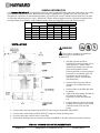
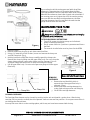
A REQUIRED CLEARANCE
“B” SIDE “C” ABOVE
IN CM IN CM IN CM
C2030 32.5 83 18 46 15 38
C3030 34.5 88 18 46 16 41
C4030 40.5 103 18 46 18 46
C5030 46.5 118 18 46 22 56
C7030 52.5 133 18 46 28 71
INSTALLATION
WARNING
This product should be installed and
serviced only by a qualified pool
professional.
1. The filter system should be
installed on a
level concrete slab or
other rigid base. Select a well
drained and vented area, one that
does not flood when it rains.
Position the filter so that the piping
connections, and winter drain are
convenient and accessible for
operation, service, maintenance
and winterizing.
2. Position filter body such that all
operation and safety labels are
visible.
3. Position filter so the filter will drain
by gravity.
4. If practical, place pump and filter in
the shade to shield it from
continuous, direct heat from the
sun.
5. Connect the pool suction plumbing
between the skimmer, pool suction
outlet (from the pool) and the
pump.
6. Connect the pump discharge (pump OUTLET) to the top port of the filter (filter INLET).
7. Connect the bottom filter port (filter OUTLET) to the pool return plumbing lines.
8. Do not locate pump controls over or near filter.
9. Verify water discharge from the manual air relief valve(MAR) is directed away from electrical devices.
B

USE ONLY HAYWARD GENUINE REPLACEMENT PARTS
Page 5 of 12 SWIMCLEAR™ CARTRIDGE FILTER ISC2031 REV B
STARTING THE PUMP and FILTER SYSTEM
WARNING
Before Starting the Pump
1. Use ONLY Hayward clamp system components; DEX2421JKIT clamp system, DEX2421J2 nut/bolt assembly,
DEX2422Z2 metal reinforced seal. Non-Hayward clamp components may fail in use and cause explosive
component separation. Verify that upper and lower filter bodies are properly secured with the filter body
clamp. Never rely on hand tightening the clamp nut to the clamp bolt. Using a ¾” socket on a torque
wrench, torque clamp nut to clamp bolt to 150 inch-lbs. (See Fig 1) Verify that the filter manual air relief
body is in the LOCK position, and no filter components are missing, damaged or not genuine Hayward
components. (See Fig 2)
2. Close filter drain. NOTE: Filter plug requires an o-ring seal. (See Fig 4)
3. Open all system valves to allow water from the pool to the filtration system and from the filter to return to
the pool.
4. Place the manual air relief valve in OPEN position. (See Fig 2)
Starting Pump
1. When starting system pump, do not stand over or near filter. If water leakage appears at filter tank clamp,
immediately turn off all system circulation pumps and all electrical power. Do not return to the filter until all
water leakage has stopped.
Reassemble the clamp system per the instructions on page 7 in this owner’s manual to stop leak.
2. Return to filter to CLOSE manual air relief valve only when a steady stream of water (not air or, air and water
mix) is discharged from the manual air relief valve.
OPERATION
WARNING
FILTERING
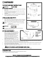
Filtration starts as soon as flow is steady through the filter. As the filter removes
dirt from the pool water, the accumulated dirt causes a resistance to flow. As a
result, the gauge pressure will rise and the flow will decrease. When the
pressure rises between 7 and 10 psi (.49 - .69 bar) above the starting pressure, or when the flow decreases below
the desired rate, clean or replace the filter cartridge elements. Once your filter is running and there is a pressure
reading, line up the green arrow with the current reading. (See Fig 3) When the pressure rises to or above the red
or second arrow, it is time to clean or replace your filter cartridge elements.
CLAMP
NUT
Manual Air Relief Shown Open
In Locked Position
Figure 3
Figure 1
CLAMP
BOLT Figure 2

USE ONLY HAYWARD GENUINE REPLACEMENT PARTS
Page 6 of 12 SWIMCLEAR™ CARTRIDGE FILTER ISC2031 REV B
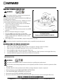
Figure 6
Manual Air Relief Shown in Open
Figure 4
By recording the initial starting pressure (with clean filter
elements) a determination can be made when the filter
cartridge elements should be replaced rather than cleaned.
After the filter elements have been cleaned and reinstalled if
the starting pressure is higher than 6 PSI above the starting
pressure with the new filter cartridge elements, the filter
cartridge elements should be replaced the next time the
gauge arrow reaches the red arrow.
MAINTAINING YOUR FILTER
WARNING
This product should be installed and serviced only by
a qualified pool professional.
FILTER DISASSEMBLY INSTRUCTIONS
1. Turn off all system circulation pumps and all electric
power on the equipment pad.
2. Set all system valves in a position to prevent water flow to
the filter.
3. The manual air relief valve must be placed in the OPEN
position. (Fig 6)
4. Remove filter drain plug (Fig 4) and drain water from filter.
5. Using 3/4” wrenches or hex sockets, loosen and remove the clamp nut
and the clamp bolt. (Fig 5)
6. Holding both ends of the filter clamp carefully spread the clamp ends.
Remove the clamp by lifting over the upper filter body. Do not to drop the
clamp during removal, because the clamp could be damaged. Do not
strike the clamp with metal tools as they can damage the clamp.
7. Lift off upper filter body. Do not use the pressure gauge to lift the upper
filter body.
REMOVING
CARTRIDGES
1. Remove the top Manifold, which is
exposed when the upper filter body is
removed. (Fig 4)
2. Remove the filter cartridge elements by
using slight rocking motion and lifting up.
3. Clean filter cartridge elements.
CLEANING CARTRIDGES
The Cartridge filter element can be cleaned by washing inside and outside with a garden hose. After hosing
cartridge, for best results, carefully brush the pleated surface to remove fine particles. Do not pressure wash as it
can damage the filter element.
You may find some debris on the cartridge pleats, which may not have been removed with hosing.
Fi
g
ure
5
Clamp Bolt Clamp Nut

USE ONLY HAYWARD GENUINE REPLACEMENT PARTS
Page 7 of 12 SWIMCLEAR™ CARTRIDGE FILTER ISC2031 REV B
Figure 9
Figure 8
Tighten clamp
bolt and nut
using a
torque
wrench to 150
inch-lbs.
Figure 7
FILTER RE-ASSEMBLY INSTRUCTIONS
WARNING
RE-INSTALLING CARTRIDGES
1. Flush and drain any dirt or debris from the bottom of the lower
filter body.
2. Flush any dirt or debris from the upper filter body and from
around the manual air relief area.
3. Carefully replace the cartridges over the hubs on the bottom
seal plate.
4. Place top manifold securely on top of cartridges, aligning the
return pipe with the port in the manifold.
CLEAN SEAL RING AND SEAL SURFACE
1. Remove filter tank seal.
2. With a clean cloth, wipe the lower filter body seal surface and
clean seal of all dirt and debris. (Fig 4) Do not use a solvent.
3. With a clean cloth wipe the upper filter body seal surface.
Notice: • Do not use any petroleum solvents to clean filter
components.
• Do not lubricate DEX2422Z2 seal.
WARNING
This product should be installed and serviced only by a
qualified pool professional.
BODY AND CLAMP RE-ASSEMBLY
1. Place the metal reinforced seal on lower
filter body. (Fig 4) Place upper filter body
on metal reinforced seal and lower filter
body in a position which allows all
operation and safety labels to be clearly
visible and the upper filter body to be
centered on the lower filter body. Press
down firmly and evenly on the upper filter
body to seat the seal. (Fig 7)
2. Replace the filter clamp around the upper
and lower filter bodies. Hold the clamp ends to position the clamp on the filter bodies with the clamp ends
adjacent to the safety and operation labels on the filter bodies. (Fig 7)
3. Insert clamp bolt through the clamp ends and thread the clamp nut onto clamp bolt with rounded end of the
nut (Fig 8) towards the ends of the clamp.
4. Never rely on hand tightening of clamp nut to clamp bolt. Using a 3/4” socket on a torque wrench, torque
clamp nut to clamp bolt to 150 inch-lbs. (Fig 9)
DO NOT HIT OR STRIKE CLAMP WITH HAMMER OR METAL TOOLS.
5. Follow Operation Instructions for “Starting the Pump and Filter System” (Page 5).
VACUUMING POOL
Vacuuming can be performed directly into the filter whenever needed.
Clean cartridges after vacuuming, if required.
Rounded end of nut
Clam
p
Bolt
Clamp Nut
Clam
p
bolt

USE ONLY HAYWARD GENUINE REPLACEMENT PARTS
Page 8 of 12 SWIMCLEAR™ CARTRIDGE FILTER ISC2031 REV B
REMOVING THE MANUAL AIR RELIEF VALVE
WARNING
This product should be installed and serviced only
by a qualified pool professional.
Your Filter comes with a Manual Air Relief Valve (MAR) pre-
installed from the factory.
For Qualified pool professionals only: If MAR valve needs
to be serviced, follow these instructions carefully.
1. Turn off all system circulation pumps and all electric
power on the equipment pad.
2. Set all system valves in a position to prevent water
from flowing to the filter.
3. The manual air relief valve must be placed in the OPEN
position.
4. Wait until all water leakage has stopped.
5. Grasp the MAR body at the flats, turn the MAR
counterclockwise until the indicator on the on the MAR
flange is aligned with the “UNLOCK” position on the
upper filter body.
6. Pull straight up to remove the MAR, a slight rocking motion may help.
This product should be installed and serviced only by a qualified pool professional.
RE-INSTALLATION OF THE MANUAL AIR RELIEF VALVE
1. Check the o-ring seals, replace as needed.
2. With a clean cloth, wipe upper filter body and o-ring groove. Remove all dirt and debris.
3. Align the notch in the MAR Flange with notch on top of the upper filter body.
4. Press the MAR straight down into the upper filter body.
5. Turn the MAR clockwise until the indicator is aligned with the “LOCK” position on the upper filter body.
6. Verify the MAR discharge points away from all electrical connections.
WINTERIZING FILTER
WARNING
This product should be installed and serviced only by a qualified pool professional.
In areas where subfreezing temperatures can be expected, the filter should be drained to protect the filter
from damage.
1. The filter should be disassembled and the filter cartridges elements cleaned or replaced.
2. Follow directions under FILTER DISASSEMBLY INSTRUCTIONS
3. Then follow REMOVING CARTRIDGES per instructions
4. Reassemble per FILTER RE-ASSEMBLY INSTRUCTIONS.
5. Be sure to leave the drain plug unattached during the winter season to avoid cracking the filter body.
Figure 10
Manual Air relief Shown Open
In Locked Position
Rotate counterclockwise to UNLOC
K

USE ONLY HAYWARD GENUINE REPLACEMENT PARTS
Page 9 of 12 SWIMCLEAR™ CARTRIDGE FILTER ISC2031 REV B
SERVICE AND REPAIRS
Consult your local authorized Hayward dealer or service center. No returns may be made directly to the factory
without the expressed written authorization of Hayward Pool Products.
SUGGESTED POOL CHEMISTRY LEVELS
pH 7.2 to 7.8
TOTAL ALKALINITY 80 to 120 ppm
CALCIUM HARDNESS 200 to 400 ppm
COMBINED CHLORINE .2 ppm Maximum
CHLORINE (STABILIZED) 1.0 to 3.0 ppm
CHLORINE STABILIZER
(Cyanuric Acid) 60 to 80 ppm
PROBLEM SOLVING LIST
LOW WATER FLOW SHORT FILTER CYCLES POOL WATER WON’T CLEAR UP
REMEDY 1. Check skimmer and
pump strainer baskets for
debris.
2. Check for restrictions in
intake and discharge
lines.
3. Check for air leak in
intake line (indicated by
bubbles returning to
pool).
1. Check for algae in pool
and super-chlorinate as
required.
2. Be sure chlorine and pH
levels are in proper range
(adjust as required).
1. Check chlorine, pH and total
alkalinity levels and adjust
as required.
2. Be sure flow rate through
filter is sufficient.
3. Operate filter for longer
periods.

USE ONLY HAYWARD GENUINE REPLACEMENT PARTS
Page 10 of 12 SWIMCLEAR™ CARTRIDGE FILTER ISC2031 REV B
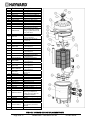
Item Part No. Description
1 ECX2712B1 Pressure Gauge
2 DEX2420Z8A O-Ring Kit (Set of 2)
3 CCX1000N Air Relief Valve Nut
4 CCX1000
V
Manual Air Relief w/O-Ring
5 DEX2420MAR2 Manual Air Relief Assembly
6a DEX2420BTC Upper Filter Body C2030
6b DEX3620BTC Upper Filter Body C3030
6c DEX4820BTC Upper Filter Body C4030
6d DEX6020BTC Upper Filter Body C5030
6e DEX7220BTC Upper Filter Body C7030
7 DEX2421J2 Clamp Bolt & Nut
8 DEX2421JKIT
Clamp System including:
Clamp, Clamp Nut and Bolt,
Hang tag, Metal Reinforced
Seal, and Labels
9 DEX2422Z2 Metal Reinforced Seal
10a CX3030C
T
op Manifold for C2030,
C3030 and C4030
10b CX5030C
T
op Manifold for C5030,
and C7030
11 CX3000J1 Air Relief Filter
12 CX2030Z3 Air Relie
f
T
ube
13a CX481XRE Cartridge Element C2030
1 of 4 Required
CX481XREPAK4 Cartridge 4 pack C2030
13b CX580XRE Cartridge Element C3030
1 of 4 Required
CX580XREPAK4 Cartridge 4 Pack C3030
13c CX880XRE Cartridge Element C4030
1 of 4 Required
CX880XREPAK4 Cartridge 4 Pack C4030
13d CX1280XRE Cartridge Element C5030
1 of 4 Required
CX1280XREPAK4 Cartridge 4 Pack C5030
13e CX591XRE Cartridge Element C7030
1 of 8 Required
CX591XREPAK4 Cartridge 4 Pack C7030
1 of 2 Required
CX7020M Mid plate Connector C7000
series only
14 DEX2400Z5 O-Ring
15a CX3031F6 Outlet Pipe C2030
15b CX3031F7 Outlet Pipe C3030
15c CX3031F8 Outlet Pipe C4030
15d CX3031F9 Outlet Pipe C5030
15e CX3031F10 Outlet Pipe C7030
16 CX3030F Inlet Elbow
17 CX3030H Assy, SwimClear Piping
18 CX3030D Bottom Seal Plate
19 DEX2420ATC Lower Filter Body
20 DEX2420LA6PAK
Label Pack: Includes all
Warning and Operation
Label’s Hang Tag, Wire Tie
and Owner’s Manual
21 SP1022CBL
K
1 ½” Drain Plug w/O-Ring
22 SX220Z2 O-ring
23 CX3035F Bulkhead Fitting
24 SPX3200UG Union Gasket (T-seal)
25 SPX3200UNKIT
Union Connection Kit
(includes Nut, Connector,
Gasket)
26 DEX2420DCKIT Strap kit (Optional)

USE ONLY HAYWARD GENUINE REPLACEMENT PARTS
Page 11 of 12 SWIMCLEAR™ CARTRIDGE FILTER ISC2031 REV B
HAYWARD® LIMITED WARRANTY
To Buyer, as original purchaser of this equipment, Hayward Pool Products, 620 Division Street, Elizabeth, New Jersey, warrants
its products free from defects in materials and workmanship for a period of ONE (1) year from the date of purchase.
Parts which fail or become defective during the warranty period, except as a result of freezing, negligence, improper
installation, use, or care, shall be repaired or replaced, at our option, without charge, within 90 days of the receipt of defective
product, barring unforeseen delays.
To obtain warranty replacements or repair, defective components or parts should be returned, transportation paid, to the place
of purchase, or to the nearest authorized Hayward service center. For further Hayward dealer or service center information,
contact Hayward customer service department. No returns may be made directly to the factory without the express written
authorization of Hayward Pool Products.
All other conditions and terms of the standard warranty apply.
Hayward shall not be responsible for cartage, removal and/or reinstallation labor or any other such costs incurred in obtaining
warranty replacements.
The Hayward Pool Products warranty does not apply to components manufactured by others. For such products, the warranty
established by the respective manufacturer will apply.
Some states do not allow a limitation on how long an implied warranty lasts, or the exclusion or limitation of incidental or
consequential damages, so the above limitation or exclusion may not apply to you.
This warranty gives you specific legal rights, and you may also have other rights, which vary from state to state.
Hayward Pool Products
620 Division Street
*Supersedes all previous publications. Elizabeth, NJ 07207

Page 12 of 12 SWIMCLEAR™ CARTRIDGE FILTER ISC2031 REV B
▲ Retain this Warranty Certificate in a safe and convenient location for your records
DETACH HERE: Fill out bottom portion completely and mail within 10 days of purchase/installation or register online.
------------------------------------------------------------------------------------------------------------
SwimClear™ Warranty Card Registration
Register online at www.haywardnet.com
Please Print Clearly:
First Name___________________________ Last Name:___________________________________
Street Address______________________________________________________________________
City____________________________________ State_______________ Zip___________________
Phone Number:_______________________________ Purchase Date:________________________
E-mail
Address________________________________________________________________________
Serial Number
(10-17 digit number)
Model
Number:______________________________________________________________________
Pool Capacity ___________(U.S. Gallons)
Please include me on all e-mail communications regarding Hayward Equipment or promotions.
Mail to: Hayward Pool Products, 620 Division Street, Elizabeth, NJ 07207
Attn: Warranty Dept
or REGISTER YOUR WARRANTY ON-LINE AT WWW.HAYWARDNET.COM
.
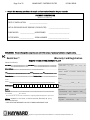
PRODUCT REGISTRATION
(Retain For Your Records)
DATE OF INSTALLATION ____________________
INITIAL PRESSURE GAUGE READING (CLEAN FILTER) _______________________
PUMP MODEL ________________ HORSEPOWER _______________________
FILTER MODEL ________________ SERIAL NUMBER _______________________
Years Pool has been in service
1 year or less 2-3 4-5 6-10 11-15 >16
Purchased from________________________________
Builder Retailer Pool Service Internet/Catalog
Company Name_______________________________
Address ______________________________________
City __________________ State______ Zip _________
Phone _______________________________________
Type of Pool:
Concrete/Gunite Vinyl Fiberglass Other_____
New Installation Replacement
Installation for:
In ground Above Ground Spa
Hayward is a registered trademark and SwimClear is a trademark of Hayward Industries, Inc.
© Hayward Pool Products. 2012 All rights reserved
-
 1
1
-
 2
2
-
 3
3
-
 4
4
-
 5
5
-
 6
6
-
 7
7
-
 8
8
-
 9
9
-
 10
10
-
 11
11
-
 12
12


Hayward SwimClear C7030 Owner's manual
- Category
- Above ground pool accessories
- Type
- Owner's manual
Ask a question and I''ll find the answer in the document
Finding information in a document is now easier with AI
Related papers
-
Hayward DEP80 Owner's manual
-
-
Hayward PoolVac Series Owner's manual
-
-
-
-
Hayward W3SP3207EE Owner's manual
-
-
Hayward Super Pump® High Efficiency High Efficiency Owner's manual
-
Hayward StarClear Plus C751 Owner's manual
Other documents
-
Pentair CC 50 User guide
-
-
-
-
Duratech DFC-039 User manual
-
-
 WaterWay 810-0183-N User manual
-
AquaPRO MEGA Cartridge Filter Owner's manual
-
emaux ICF230 User manual
-
