
heating.danfoss.com/new-solutions/ectemp-smart
Danfoss ECtemp™ Smart
Intelligent Electronic Timer Thermostat
with Wi-Fi connectivity and App control
Installation Guide

Danfoss ECtemp™ Smart
Installation Guide2
1 Introduction
ECtemp™ Smart is an electronic programmable timer
thermostat used for controlling electrical floor heating
elements. The thermostat is designed for fixed installation
only and can be used for both direct heating of the entire
room and for comfort heating of the floor. Among others,
the thermostat has the following features:
1 Introduction . . . . . . . . . . . . . . . . . . . 2
2 Technical Specifications . . . . . . . . . . . . 4
3 Safety Instructions . . . . . . . . . . . . . . . 6
4 Mounting Instructions . . . . . . . . . . . . . 8
5 Display Symbols. . . . . . . . . . . . . . . . 12
6 Configuring. . . . . . . . . . . . . . . . . . . 18
7 Settings . . . . . . . . . . . . . . . . . . . . . 19
8 Warranty. . . . . . . . . . . . . . . . . . . . . 22
9 Disposal Instruction . . . . . . . . . . . . . 22
Table of Contents

Danfoss ECtemp™ Smart
3Installation Guide
• A touchscreen display with light.
• An easy-to-follow menu-driven programming and
operation.
• An installation wizard with room/floor type-specific
setup (requires an app).
• Support for multiple frame systems.
• Compatible with several 3rd party NTC sensors.
• Thermostat settings can be specified before instal-
lation and imported to the thermostat using a
web-generated code, or copied from a thermostat in
a similar installation.
• Smart access to thermostat settings after installa-
tion by using a web code interface, for easy setup or
remote troubleshooting.
Regarding Connectivity:
• 10 smart devices (like Smartphone or Tablet) can be
connected to 1 thermostat.
• 2 smart devices can be in contact with the thermo-
stat at the same time.
ECtemp™ SMART REQUIRES WORKING WIFI
TO FUNCTION

Danfoss ECtemp™ Smart
Installation Guide4
More information on this product can also be found at:
http://heating.danfoss.com/new-solutions/ectemp-smart
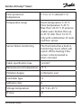
2 Technical Specifications
Operation voltage 220-240 V~, 50/60 Hz
Standby power consumption Max. 0,40 W
Relay:
Resistive load
Inductive load
Max. 16 A / 3680 W @ 230 V
Max. 1 A cos φ= 0,3
Sensing units NTC 6,8 kOhm at 25°C
NTC 10 kOhm at 25°C
NTC 12 kOhm at 25°C
NTC 15 kOhm at 25°C (Default)
NTC 33 kOhm at 25°C
NTC 47 kOhm at 25°C
Sensing values:
(Default NTC 15 K)
0°C
20°C
50°C
42 kOhm
18 kOhm
6 kOhm
Control PWM (Pulse Wide Modulation)
Ambient temperature 0 ° to +30 °C

Danfoss ECtemp™ Smart
5Installation Guide
Frost protection
temperature
5 °C to +9 °C (default 5 °C)
Temperature range Room temperature: 5-35 °C.
Floor temperature: 5-45 °C.
Max. floor: 20-35 °C (if unrecov-
erable seal is broken then up
to 45 °C). Min. floor: 10-35 °C,
only with combination of room
and floor sensor.
Sensor failure monitoring The thermostat has a built-in
monitoring circuit, which will
switch off the heating if the
sensor is disconnected or
short-circuited
Cable specification max. 1x4 mm
2
Ball pressure test temperature 75 °C
Pollution degree 2 (domestic use)
Controller type 1C
Software class A
Storage temperature -20 °C to +65 °C
IP class 21

Danfoss ECtemp™ Smart
Installation Guide6
Protection class Class II -
Dimensions 85 x 85 x 20-24 mm
(in-wall depth: 22 mm)
Weight 127 g
Electrical safety and Electro-Magnetic Compatibility for
this product is covered by the compliance with the EN/IEC
Standard “Automatic electrical controls for household and
similar use”:
• EN/IEC 60730-1 (general)
• EN/IEC 60730-2-9 (thermostat)
3 Safety Instructions
Make sure the mains supply to the thermostat is turned
off before installation.
Important: When the thermostat is used to control a
floor heating element in connection with a wooden floor
or similar material, always use a floor sensor and never set
the maximum floor temperature to more than 35 °C.

Danfoss ECtemp™ Smart
7Installation Guide
Please also note the following:
• The installation of the thermostat must be done by an
authorized and qualified installer according to local
regulations.
• The thermostat must be connected to a power supply
via an all-pole disconnection switch.
• Always connect the thermostat to continuous power
supply.
• Do not expose the thermostat to moisture, water,
dust, and excessive heat.
• This thermostat can be used by children aged from 8
years and above and persons with reduced physical,
sensory or mental capabilities or lack of experience
and knowledge, if they have been given supervision
or instruction concerning use of the appliance in a
safe way and understand the hazards involved, by a
person responsible for their safety.
• Children should be supervised to ensure that they do
not play with the thermostat.
• Cleaning and user maintenance shall not be made by
children without supervision.

Danfoss ECtemp™ Smart
Installation Guide8
4 Mounting Instructions
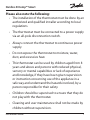
Please observe the following placement guidelines:
Place the thermostat at a suitable height on the wall
(typically 80-170 cm.).
The thermostat should not be placed in wet rooms.
Thermostat must be placed outside zone 2. Place it
in an adjacent room and use floor sensor only.
Always place the thermostat according to local
regulation on IP classes.
Do not place the thermostat on the inner side of a
poorly insulated exterior wall.
Always install the thermostat at least 50 cm from
windows and doors, due to draft, when using regu-
lation in: floor and room mode or room alone mode.
Do not place the thermostat in a way that it will be
exposed to direct sunlight.

Danfoss ECtemp™ Smart
9Installation Guide
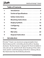
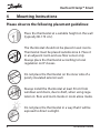
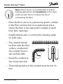
Note: A floor sensor is recommended in all floor
heating applications and mandatory to thin mats
under wooden floors to reduce the risk of
overheating the floor.
• Place the floor sensor in a protecting plastic conduit
in the floor construction in an appropriate place,
where the floor is not exposed to sunlight or draft
from door openings.
• Equally distant and >2 cm from the heating cables
on both sides.
• The conduit should
be flush with the floor
surface, countersink
the conduit if neces-
sary and possible.
• Route the conduit to
the connection box.
• The bending radius of the conduit must be min 50
mm.
12
≥

Danfoss ECtemp™ Smart
Installation Guide10
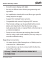
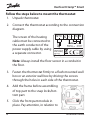
Follow the steps below to mount the thermostat:
1. Unpack thermostat
2. Connect the thermostat according to the connection
diagram.
The screen of the heating
cable must be connected to
the earth conductor of the
power supply cable by using
a separate connector.
Note: Always install the floor sensor in a conduit in
the floor.
3. Fasten the thermostat firmly to a flush mounted wall
box or an exterior wall box by driving the screws
through the holes in each side of the thermostat.
4. Add the frame before assembling
of top part to the snap locks/bot-
tom part.
5. Click the front part module in
place. Pay attention, in relation to
IP21
T30
Mains
220-240V~
50-60 Hz
Maximum
Load 16 (1) A
Sensor
NTC
Danfoss A/S
Nordborgvej 81
6430 Nordborg
Denmark
NLL
L
O
A
D
N
L
O
A
D
Standby maximum 0.4 Watt

Danfoss ECtemp™ Smart
11Installation Guide
the female header, in not to bending the connectors.
Press carefully until the frame is fixed against the
rubber gasket.
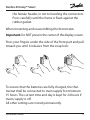
When mounting and reassembling the thermostat.
Important: Do NOT press in the center of the display screen.
Press your fingers under the side of the front part and pull
toward you until it releases from the snap lock:
To ensure that the batteries are fully charged, the ther-
mostat shall be connected to main supply for minimum
15 hours. The current time and day is kept for 24 hours if
mains supply is off.
All other settings are stored permanently.

Danfoss ECtemp™ Smart
Installation Guide12
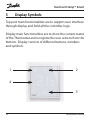
5 Display Symbols
Top part main functionalities are to support user interface
through display and hold all the controller logic.
Display main functionalities are to show the current status
of the Thermostat and recognize the user actions from the
buttons. Display consists of different buttons, numbers
and symbols.
1
4
2
3

Danfoss ECtemp™ Smart
13Installation Guide
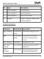
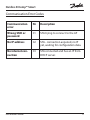
Nr. Type Description
1 Button/Symbol Control button
2 Button/Symbol Arrow Up button
3 Button/Symbol Arrow Down button
4 Symbol 3 digit 7 segment numbers with
comma separator
Symbol indications
Indication Mode/State Description
Blue - blinking Access Point
Mode
Thermostat ready for set-up
Blue Access Point
Mode
Smart phone connected
directly to thermostat for
set-up
Red - blinking Fault state Displays Error code
Red - slow
pulsing
Active Mode Indicating heating the floor
(Relay on)
Green -
constant
Active Mode Thermostat active and con-
nected to WiFi(Relay off)

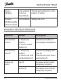
Danfoss ECtemp™ Smart
Installation Guide14
Green –
blinking
Active Mode
& Access
Point Mode
Thermostat waiting for confir-
mation of action
Arrows –
blinking rapidly
when touched
Active Mode Safety lock is on
Interaction directly on thermostat
Function Button Description
Turn thermo-
stat on
1. Touch any
button
2. Touch control
button (1)
Thermostat switch on
and display temperature
Turn thermo-
stat off
1. Touch any
button
2. Touch and hold
control button (1)
Thermostat display will
turn on
Thermostat count down
and switch off
Adjust set-
point
Up (2) Increases active mode/
temporary set point
Down (3) Decreases active mode/
temporary set point

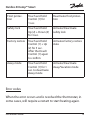
Danfoss ECtemp™ Smart
15Installation Guide
Frost protec-
tion
Touch and hold
Control (1) for
1 sec.
Deactivate frost protec-
tion
Safety lock Touch and hold
Up (2) + Down (3)
for 3 sec.
Activate/Deactivate
safety lock
Factory restore Touch and hold
Control (1) + Up
(2) for 5 sec.
After that touch
Control (1) again
to confirm
Activates factory restore
state
Away mode Touch and hold
Control (1) for 1
sec. to deactivate
Away mode
Activate/Deactivate
Away/Vacation mode
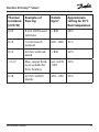
Error codes
When the error occurs and is resolved the thermostat, in
some cases, will require a restart to start heating again.

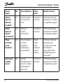
Danfoss ECtemp™ Smart
Installation Guide16
Error
type
Nr. Description Solu-
tion
Need restart
Floor
Sensor
discon-
nected
E1 Connection
to sensor is
lost
Contact
service
The thermostat
requires a restart
to operate again.
Floor
Sensor
short-
circuited
E2 Sensor
short-
circuited
Contact
service
The thermostat
requires a restart
to operate again.
Ther-
mostat
over-
heated
E3 Thermostat
is over-
heated,
heating is
turned off
Wait
until
ther-
mostat
cools
down
The thermostat
requires no
restart, but will
start heat-
ing when the
temperature is
lowered
Unrecov-
erable
error
E4 Room
temperature
sensor value
too high or
too low
Contact
service
The thermostat
requires a restart
to operate again.

Danfoss ECtemp™ Smart
17Installation Guide
Communication Error Codes
Communication
error
Nr. Description
Wrong SSID or
password
C1 STA trying to connect to the AP
No IP address C2 STA - connection acquired, no IP
yet, waiting for configuration data.
No internet con-
nection
C3 STA connected and has an IP from
DHCP server.

Danfoss ECtemp™ Smart
Installation Guide18
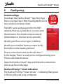
6 Configuring
Download App
Download the Danfoss Smart™ App from App
Store or Google Play or http://heating.danfoss.com/
new-solutions/ectemp-smart.
Find WiFi name and password for the WiFi
network, that you would like to connect your
thermostat to. If in doubt contact network
administrator or internet service provider.
Identify your floor sensor type ( in kOhm).
Identify your installed heating output (in W),
from label on the heating element.
Power on the thermostat, and it will show “-“
in the display. Then it is ready to be configured using your
iPhone and Android device.
Open the Danfoss Smart™ App and follow the instructions
and set-up flow in the App.
Danfoss ECtemp™ Smart indication
The Danfoss ECtemp™ Smart shows “–” indicating that power
is ON, but still need to be configured.

Danfoss ECtemp™ Smart
19Installation Guide
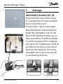
7 Settings
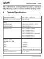
IMPORTANT DURING SET-UP
Select whether only a floor sensor
or a combination of room and floor
sensor should be used.
A “room only” option is also avail-
able, but requires that you have to
break the small plastic seal on the
back of the display module, e.g. us-
ing a screwdriver; it will be possible
to set the maximum floor tempera-
ture up to 45°. Furthermore, it will be
possible to use only a room sensor.
However, this option is not recom-
mendable due to an increased risk
of overheating the floor.

Danfoss ECtemp™ Smart
Installation Guide20
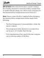
IMPORTANT: When the thermostat is used to control a
floor heating element in connection with a wooden floor
or similar material, always use a floor sensor and never set
the maximum floor temperature to more than 35°C.
Note: Please contact the floor supplier before changing
the maximum floor temperature and be aware of the
following:
• The floor temperature is measured there, where the
sensor is placed.
• The temperature of the bottom of a wooden floor
can be up to 10˚C higher than the top.
• Floor manufactures often specify the max. tempera-
ture on the top surface of the floor.
Page is loading ...
Page is loading ...
Page is loading ...
Page is loading ...
-
 1
1
-
 2
2
-
 3
3
-
 4
4
-
 5
5
-
 6
6
-
 7
7
-
 8
8
-
 9
9
-
 10
10
-
 11
11
-
 12
12
-
 13
13
-
 14
14
-
 15
15
-
 16
16
-
 17
17
-
 18
18
-
 19
19
-
 20
20
-
 21
21
-
 22
22
-
 23
23
-
 24
24


Danfoss ECtemp Smart Owner's manual
- Type
- Owner's manual
- This manual is also suitable for
Ask a question and I''ll find the answer in the document
Finding information in a document is now easier with AI
Related papers
-
Danfoss CF2+ Installation guide
-
-
Danfoss ECtemp Touch Installation guide
-
-
-
-
-
Danfoss 140F1010 Operating instructions
-
Danfoss 140F1070 Operating instructions
-
Other documents
-
DEVI 19121445 Installation guide
-
DEVI 140F1070 Operating instructions
-
-
 Aircalo PB 172 Installation and Maintenance Manual
-
DEVI 140F1080 Operating instructions
-
HEATIT 5430589 User manual
-
HEATIT 5430588 User manual
-
-
 Veria Control B35 Installation guide
-
DEVI 140F1137 Operating instructions

