Page is loading ...

MSA Sure-Strong™ Bridge
Rescue Frame P/N# CE 108-001
Application, Operation, Maintenance & Inspection Instructions Manual
Ref: BRF-001 Date: 06/06/01
Application
The MSA Bridge Rescue Frame is
designed as a portable emergency
anchorage for retrieval of railway bridge
workers from below the bridge deck.
In most cases, the worker cannot be
lowered, therefore the anchor point
must be above the level of the bridge
deck and positioned in such a way that
retrieval is possible.
Printed in U.S.A.
Copyright © 2001 MSA
All rights reserved. No part of this
Catalogue covered by the copyrights
hereon may be reproduced or copied
in any form or by any means - graphics,
electronic or mechanical, including
photocopying, recording, taping or
information storage and retrieval systems
-without the written permission of MSA.
THESE INSTRUCTIONS MUST BE
PROVIDED TO THE USER.
MANAGEMENT AND USER
MUST READ AND UNDERSTAND
THESE INSTRUCTIONS; FAILURE
TO DO SO COULD RESULT IN
SERIOUS INJURY OR DEATH.
WARNING
2250 South Tejon Street, Englewood, CO 80110, USA
USA Phone: 1-800-672-2222 Fax: 1-800-967-0398 Canada Phone: 1-888-396-1067
• Web Site: www.msanet.com • e-mail: rose@msanet.com
Please read this manual.
This information is vital to your safety.

The primary function of the Bridge Rescue Frame is to
retrieve workers stranded or injured on a fall arrest
system on the field side of the bridge deck. With a minor
modification it becomes a tripod that can be used for
retrieval through the ties between the rails.
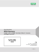
In the standard configuration (fig. 1) the frame leans
forward, which positions the apex (anchor eye) over the
field side of the ties. The two leading legs are secured
to the rail by foot brackets which are connected with 1/4
in. steel cable to prevent spreading. This cantilever
design distributes a portion of the load directly on one
rail while the remainder of the load is anchored to the
opposite rail with a 3/8 in. steel cable at the end of the
rear leg.
For use as a tripod (fig. 2), the lower forward legs and
foot brackets are reversed so legs lean inward to position
the apex over the middle of the bridge deck. The rear
leg is shortened and attached to a rail connector on the
other rail.
A raising system can be directly attached to the anchor
eye or with optional bracket, a winch can be anchored
2 of 8
Function
Tripod Modification
AT
7
AT
DT
G
2a
2b
(fig. 2)
Standard Configuration
C
F
B
A
2b
2a
D
(fig. 1)
F
6
5
A
E
4
3
D
B
1
A
Inches cm
*A 132 335
*A
T
86 218
**B 119 302
C 60 152
C
T
12 30
***D 88 224
***D
T
95 241
**E min 2.7 6.9
**E max 9.5 24
**F 96 244
G 12.5 31
* Measurements taken with rear
leg attachment at minimum length
** Measurements B,E and F are
constant
***D and D
T
are measured to top of
tie.
Copyright © 2000 MSA

3 of 8
WARNING: IT IS THE RESPONSIBLITY OF THE USERS COMPANY TO HAVE A WRITTEN RESCUE PLAN
WHICH MUST BE CONSIDERED BEFORE THIS EQUIPMENT IS USED. THESE PROCEDURES MUST BE PRACTICED
IN ANTICIPATION OF AN EMERGENCY. ALTHOUGH IT IS POSSIBLE TO ERECT THE FRAME ALONE, MSA WOULD
RECOMMEND THAT AT LEAST 2 WORKERS ARE AVAILABLE FOR OPERATION OF THE BRIDGE RESCUE FRAME IN
THE EVENT OF AN INCIDENT.
THE BRIDGE RESCUE FRAME AND APPROVED HOISTING EQUIPMENT MUST BE AT THE WORK SITE AND AVAILABLE
FOR RESCUE WHEN BRIDGE WORKERS ARE BELOW THE BRIDGE DECK OR USING FALL PROTECTION SYSTEMS.
1. Carry Rescue Frame and hoisting equipment to incident site.
2. Lay Rescue Frame between rails just before reaching rescue site. Use a fall protection system at all times during
erection, in use and disassembling. Secure all equipment to prevent unintentional release through ties. Remember,
the casualty is below your position.
3. Assess exact position of casualty; decide if frame or tripod configuration is more suitable. Open carrying case.
Part Number CE 108-001
1. Head Assembly
1/4 in bent plate aluminum
1/2 in anchor plate, 11/16 in carabiner hole
galvanized steel hardware
2a. Forward Legs
2b. Rear Leg
hollow square 2 in (5.0cm) outer leg
1 11/16 in (4.0cm) inner leg
extruded aluminum alloy
1/2 in (13mm) leg securing pin
3. Rear Leg Rail Attachment
solid aluminum block insert
3/4 in galvanized steel bolt with jaw end
5/8 in (16mm) securing pin and safety cotter
4. Steel Anchor Cable Part # CE 108-014
5 ft x 3/8 in galvanized steel
Flemish eye splice terminations
5. Foot Brackets
1/4 in bent plate aluminum
Specifications
WARNING
THE USER SHOULD READ THIS INSTRUCTION INFORMATION THOROUGHLY. SAFE USE OF THE RESCUE FRAME
IMPLIES THAT THE APPROPRIATE FALL PROTECTION AND RESCUE TECHNIQUES ARE EMPLOYED. FALL PROTECTION
SHOULD BE USED AT ALL TIMES DURING ASSEMBLY, USE AND DISASSEMBLY OF THE RESCUE FRAME.
RESCUE TECHNIQUES MUST BE ACQUIRED AS A RESULT OF A SUITABLE PERIOD OF TRAINING AND EXPERIENCE.
DURING RESCUE PRACTICE SESSIONS ANCHOR THE LOAD TO A SECONDARY INDEPENDENT ANCHOR SYSTEM
CAPABLE OF ARRESTING THE LOAD IN THE EVENT OF TOTAL FAILURE OF THE PRIMARY SYSTEM.
RESCUE PRACTICES SHOULD BE SUPERVISED BY A PERSON WITH SUFFICIENT TRAINING AND EXPERIENCE TO
PROVIDE ASSISTANCE IN CASE OF EMERGENCY OR IN THE EVENT THAT A DANGEROUS SITUATION DEVELOPS.
6. Leg Security Cable
1/4 in galvanized steel, vinyl coated
with Flemish spliced terminations
7. Cordura Nylon Storage Bag Part # CE 108-001-BG
with dual carrying handles. (not shown)
8. Optional (Tripod Modification)
Rail Connector Part # CE 108-015
G40.21-92 grade 44 W plate steel
fits 85 to 136 lb rail
total weight 5.5 lbs (2.5kg)
• safe working load 1 person 310 lbs (140 kg)
2 persons 620 lbs (281 kg)*
• collapsed storage size 10 ft (3.05m)
• total system weight 64lbs (29kg)
(not including tripod modification kit)
• proof loaded to 3600 lbs. (16kN)*
• maximum observed support strength during qualification
testing, 4825 lbs (21.5kN).
• meets and exceeds ANSI proof load requirements
(3600 lbs [16kN]) for anchorage connectors in the
presence of certification by an engineer. (Z359.1-1992).
* when rescuer uses an approved independently
anchored fall arrest system.
Operating Instructions
Copyright © 2000 MSA

4 of 8
Operating Instructions
(fig. 4)
(fig. 3)
NOTE: BRIDGE RESCUE FRAME SHOULD BE STORED STANDARD CONFIGURATION WITH FORWARD
LEGS PINNED AND REAR LEG IN FULLY COLLAPSED POSITION.
Standard Set Up
4. Unzip bag, turn frame so head assembly eye is down (In standard
configuration arrows on legs will point to "STANDARD" marking;
(fig 3). Pull rear leg security pin and adjust rear leg to fully extended
position (winch attachment pin hole will be exposed), replace pin
(fig 4). Ensure that rear leg attachment pin is removed, jaw connection
is tightened, and hole alignment is perpendicular to rail (fig 5).
5. Line up casualty’s position between ties and mark rail furthest away
from casualty for cable sling position. Lay cable sling on ties close
to marked rail. Connect raising system or winch redirection pulley
and cable at carabiner hole in head assembly before installation on
rails.
NOTE: USE ONLY HOISTING SYSTEMS APPROVED BY MSA.
FOLLOW MANUFACTURER’S INSTRUCTIONS. IF USING WINCH,
UNWIND 10 FT OF CABLE AND LAY WINCH ON BRIDGE DECK
BEFORE INSTALLING REDIRECTION PULLEY.
(fig. 5)
(fig. 7) (fig. 6)
Copyright © 2000 MSA

6. Instruct assistant to wrap anchor cable around rail twice at marked
location. Place both anchor cable eyes in rear leg attachment. Insert
pin in rear leg attachment (Fig. 6). Secure with cotter pin.
7. Push end of rear leg over rail (Fig. 7). Lift forward legs vertically above
rail on field side of bridge, (Fig. 8) spread legs and place on rail. Check
rear leg is centered between forward legs and forward legs are spread
as far as leg security cable allows. Check leg securing pins (3) for
security.
8. Check cable sling swage is not caught on rail and ensure cable is
seated tightly on rail (Fig. 9).
9. If using a winch, connect winch bracket to rear leg at middle hole.
Tripod Set Up
10. Unzip bag, turn frame so head assembly eye is down. Pull leg security
pins on forward legs and remove inner legs (Fig. 10). Reverse legs
so the word "TRIPOD" is facing up and leg security cable is on inside
of legs. Ensure rear leg is in fully collapsed position and leg securing
pin is in place as in (Fig. 11).
11. Remove tripod modification kit (Rail Connector).
12. Disassemble Rail Connector profile plates. Place one profile plate on
the crown of the rail in line with the casualty’s position. Align the
receiving bolts and holes of other profile plate and connect plates
(Fig. 12).
5 of 8
Operating Instructions
WARNING
IT REQUIRES SOME EFFORT TO HOLD REAR LEG IN POSITION AS BRIDGE
FRAME IS TIPPED FORWARD. LOWER SLOWLY ENSURING THAT FOOT
BRACKETS STAY ON THE RAIL. ASSISTANT(S) CAN HOLD FOOT BRACKETS
IN POSITION IF NECESSARY.
(fig. 10) (fig.12)
(fig.8)
(fig.9)
(fig. 11)
Copyright © 2000 MSA

Operating Instructions
6 of 8
13. When the profile plates are flush with
each other (Fig. 13), slide plates in
opposite directions parallel to the
rail. The plates are now locked on
the crown of the rail. (Fig. 14)
14. Turn frame perpendicular to the rail
with head assembly on the Rail
Connector side of bridge deck and
turn so anchor eye is up.
15. Instruct assistant(s) to raise and spread
forward legs vertically while holding
rear leg (Fig. 15). Ensure leg security
cable is free of obstructions. Place foot
brackets on the rail with head assembly
directly inline with the Rail Connector.
16. Lean forward legs toward opposite
rail while lifting rear leg and place
rear leg attachment jaw on top of
Rail Connector (Fig. 16).
17. Tip Rail Connector towards centre
of bridge and connect to rear leg
attachment jaw with security pin
(Fig. 17). Secure with cotter pin.
Ensure that rail slider is directly below
tripod head and does not move
during operation.
18. Connect hoisting system to carabiner
hole. If using winch, unwind 10 ft.
(3 m) of cable and connect cable
and pulley to carabiner hole. Attach
winch to leg with bracket and secure
with leg securing pin. Recheck all
leg securing pins.
(fig. 15)
(fig. 16)
(fig. 13)
(fig. 14)
(fig. 17)
Copyright © 2000 MSA

1. The MSA Sure-Strong Rescue Frame shall be
inspected before practice sessions, after use and
additionally by a competent person other than the
user at intervals of no more than one year.
Inspections must be recorded in the Inspection
Checklist.
2. When inspection reveals defects, damage, or
inadequate maintenance of any component in the
system, the component affected shall be removed
from service to undergo adequate corrective
maintenance before return to service. Removal from
service may imply that defects or damage will result
in retiring and replacing some components.
3. Remove a unit from service if:
• it has been subjected to excessive shock loading;
• markings (labels) are illegible or absent;
• there is evidence of defects or damage to hardware
elements including cracks, sharp edges,
deformation, corrosion, chemical attack, excessive
heating, alteration, excessive aging or excessive
wear;
• there are kinks or other damage to anchor cable;
• there is evidence of improper function, improper
fit of components or if any component is missing.
4. MSA or persons or entities authorized in writing by
the manufacturer, shall make repairs to equipment.
No unauthorized repairs and/or modifications are
allowed.
1. Maintenance and storage of Bridge Rescue Frame
shall be conducted by the user’s organization in
accordance with MSA instructions. Unique issues,
which may arise due to conditions of use, should be
addressed with MSA.
2. Components which are in need of or scheduled for
maintenance shall be tagged as “do not use” and
removed from service.
3. Store in clean, dry area specifically set aside for
emergency equipment.
• The MSA Sure-Strong™ Bridge Rescue Frame shall
comply to and be used with consideration to all
government or other applicable regulations and
standards.
• The MSA Sure-Strong™ Bridge Rescue Frame is a
engineered and thoroughly tested product. The
system must be used as described in these
instructions. All additional rescue equipment intended
for use with the product must not be used without
written approval by MSA. If the buyer chooses to
disregard this warning he assumes sole responsibility
for the integrity of the entire system.
• The MSA Sure-Strong™ Bridge Rescue Frame is
designed as a rescue anchorage connector. It must
not be used as a fall arrest anchorage. In an
emergency the Bridge Rescue Frame can
accommodate two workers or up to 600 lbs (272kg)
simultaneously. Suspension of rescue personnel
must be backed up by an independently anchored
secondary system capable of supporting 5000 lbs
(22.2kN).
• Do not use Bridge Rescue Frame and hoisting system
adjacent to moving machinery, electrical hazards or
in the presence of excessive heat, open flame or
molten metal.
• Apply forces to the system only in the direction in
indicated by specification drawings. Forces applied
in other directions may cause stress which the system
is not designed to withstand.
• Rail connector must not be used for fall protection.
Inspection
Design Statements
Maintenance and Storage
7 of 8
NOTE: A PERSON WITHIN THE USER’S ORGANIZATION MUST BE APPOINTED TO BE RESPONSIBLE FOR INSPECTION,
MAINTENANCE AND STORAGE OF EQUIPMENT. THE BRIDGE RESCUE FRAME MUST BE SEALED TO
DISCOURAGE TAMPERING AND ONLY REMOVED FOR RESCUE PRACTICES, YEARLY INSPECTIONS AND IN
THE EVENT OF AN EMERGENCY.
Copyright © 2000 MSA

Made i n U.S.A.
WARNINGS
Englewood, Co lorado, USA
SURE-STRONG™
BRIDGE RESCUE
FRAME
DATE :
SAFE WORKING LOAD:
Extruded aluminum,
forged steel.
MODEL: CE 107-001
600 lbs (272kg)
MATERIAL:
Use of fall protectio n is
required wh en exposed to a
potential fall .
If inspectio n reveals
damage, misuse or
alteration o f equip ment.
Inspect equi pment pr ior to
each use.
Suspensio n of perso nnel
must be b acked u p by an
indep enden tly anch ored
secondar y system cap able
of suppo rtin g 5000 l bs
(22.7kN) wi th deformatio n.
Use in accord ance with
instruction man ual
included with pr oduct at
time of shipment. Fail ure
to co mply cou ld resu lt in
serious i njury or death.
XX-XX-XX
8 of 8
Inspection Checklist
Model No.
Date
Inspected By
Description
Comments
HEAD ASSEMBLY AND HARDWARE
FORWARD LEG ASSEMBLY
FORWARD LEG SECURITY PINS (2)
FOOT BRACKETS
LEG SECURITY CABLE
REAR LEG ASSEMBLY
SECURITY PIN (1)
ATTACHMENT JAW
JAW SECURING PIN
SAFETY PIN
CABLE ANCHOR SLING
RAIL CONNECTOR
Serial #
SERIAL #
#232
TO BE USED WITH MSA SURE-STRONG™
BRIDGE RESCUE FRAME ONLY.
DO NOT USE FOR FALL ARREST.
WARNING
Copyright © 2000 MSA
/