
QUICK INSTALL GUIDE
DART BCON FOR LVDS
DEVELOPMENT KIT

Basler AG
An der Strusbek 60–62
22926 Ahrensburg
Germany
All material in this publication is subject to change without notice and is
copyright Basler AG.

3
TABLE OF CONTENTS
TABLE OF CONTENTS
INTRODUCTION . . . . . . . . . . . . . . . . . . . . . . . . . . . . . . . . . . . . . . . . . . . . . . . 5
About this Document . . . . . . . . . . . . . . . . . . . . . . . . . . . . . . . . . . . . . . . . . . . . 5
Target Audience . . . . . . . . . . . . . . . . . . . . . . . . . . . . . . . . . . . . . . . . . . . . . . . . . 5
SAFETY INSTRUCTIONS . . . . . . . . . . . . . . . . . . . . . . . . . . . . . . . . . . . . . . . . 6
Camera Precautions . . . . . . . . . . . . . . . . . . . . . . . . . . . . . . . . . . . . . . . . . . . . . 7
Environmental Requirements . . . . . . . . . . . . . . . . . . . . . . . . . . . . . . . . . . . . . 7
Warranty Precautions . . . . . . . . . . . . . . . . . . . . . . . . . . . . . . . . . . . . . . . . . . . . 8
DELIVERED PARTS . . . . . . . . . . . . . . . . . . . . . . . . . . . . . . . . . . . . . . . . . . . . 9
HARDWARE INSTALLATION . . . . . . . . . . . . . . . . . . . . . . . . . . . . . . . . . . . . 10
Overview of the Components . . . . . . . . . . . . . . . . . . . . . . . . . . . . . . . . . . . 10
Installing the Basler dart BCON for LVDS Development Kit . . . . . . . . . . 11
ACQUIRING YOUR FIRST IMAGES . . . . . . . . . . . . . . . . . . . . . . . . . . . . . . . 14
Prerequisites . . . . . . . . . . . . . . . . . . . . . . . . . . . . . . . . . . . . . . . . . . . . . . . . . . . 14
Step 1: Installing the Required Software on the Host Computer . . . . . .15
Step 2: Connecting to the Processing Board via Terminal . . . . . . . . . . . .15

4
TABLE OF CONTENTS
Step 3: Changing the Processing Board’s MAC Address . . . . . . . . . . . . .18
Step 4: Determining the Processing Board’s IP Address . . . . . . . . . . . . .19
Step 5: Connecting to the Processing Board via RDP . . . . . . . . . . . . . . .21
Step 6: Acquiring Images Using the pylon Viewer . . . . . . . . . . . . . . . . . 22
NEXT STEPS . . . . . . . . . . . . . . . . . . . . . . . . . . . . . . . . . . . . . . . . . . . . . . . . . 23
Developer Resources . . . . . . . . . . . . . . . . . . . . . . . . . . . . . . . . . . . . . . . . . . . 23
Technical Support . . . . . . . . . . . . . . . . . . . . . . . . . . . . . . . . . . . . . . . . . . . . . . 23
SPECIFICATIONS . . . . . . . . . . . . . . . . . . . . . . . . . . . . . . . . . . . . . . . . . . . . .24
Camera Specifications . . . . . . . . . . . . . . . . . . . . . . . . . . . . . . . . . . . . . . . . . . 24
Processing Board Specifications . . . . . . . . . . . . . . . . . . . . . . . . . . . . . . . . . 25
Carrier Board Specifications . . . . . . . . . . . . . . . . . . . . . . . . . . . . . . . . . . . . . 25
Lens Specifications . . . . . . . . . . . . . . . . . . . . . . . . . . . . . . . . . . . . . . . . . . . . . 26
Power Supply Specifications . . . . . . . . . . . . . . . . . . . . . . . . . . . . . . . . . . . . 26
Block Diagram of Carrier Board . . . . . . . . . . . . . . . . . . . . . . . . . . . . . . . . . . 27
DISCLAIMER AND LICENSING INFORMATION . . . . . . . . . . . . . . . . . . . . . 28
Disclaimer . . . . . . . . . . . . . . . . . . . . . . . . . . . . . . . . . . . . . . . . . . . . . . . . . . . . . 28
Software Licensing . . . . . . . . . . . . . . . . . . . . . . . . . . . . . . . . . . . . . . . . . . . . . 29

5
INTRODUCTION
INTRODUCTION
About this Document
This document provides information about how to install the Basler dart
BCON for LVDS Development Kit. It also provides step-by-step instructions
that help you acquire your first images with the included Basler dart BCON
for LVDS camera.
Target Audience
The Basler dart BCON for LVDS Development Kit is aimed at experienced
hardware and software engineers proficient in electronics, software
development, and embedded system design.
This document is written for a target audience that has intermediate to
advanced technical skills in the areas mentioned above.
The document assumes that users have experience in the following areas:
System on Chip (SoC) or System on Module (SoM) architectures
Serial communication
FPGA programming
Development of frame grabbing procedures
Bus architectures such as IC
Embedded Linux operating systems

6
SAFETY INSTRUCTIONS
SAFETY INSTRUCTIONS
Electric Shock Hazard: Unapproved power supplies may cause electric
shock. Serious injury or death may occur.
Only use the power supply delivered with the Basler dart BCON for LVDS
Development Kit. Do not use other power supplies.
Fire Hazard: Unapproved power supplies may cause fire and burns.
Only use the power supply delivered with the Basler dart BCON for LVDS
Development Kit. Do not use other power supplies.
Damage Hazard: Electrostatic discharge (ESD) can damage the
components of the Basler dart BCON for LVDS Development Kit.
Use anti-static clothes and materials, e.g., conductive shoes, anti-static
gloves, and ESD protection wrist straps to decrease the risk of
electrostatic discharge.
Control the humidity in your environment. Low humidity can cause ESD
problems.
DANGER
WARNING
NOTICE

7
SAFETY INSTRUCTIONS
Radio Interference Hazard: This is a Class A product. In residential
environments, this product may cause radio interference, in which case the
user may be required to take adequate measures.
Camera Precautions
Precautions related to the operation of the Basler dart BCON for LVDS
camera can be found in the Basler Product Documentation available at
docs.baslerweb.com.
Environmental Requirements
The Basler dart BCON for LVDS Development Kit is intended for indoor use
at normal room temperature only.
For specific environmental requirements of the components, see the
following documents:
Basler Product Documentation
Available at docs.baslerweb.com.
MicroZed Hardware User Guide
You can download it from www.microzed.org.
NOTICE

8
SAFETY INSTRUCTIONS
Warranty Precautions
To ensure that your warranty remains in force, adhere to the following
guidelines:
Follow the safety instructions.
Do not modify the hardware components in any way. Do not remove
parts from the board or solder in new parts.
Do not allow, e.g., liquid, flammable, or metallic material to get in
contact with the board.
Observe the warranty information given in the Basler Product
Documentation available at docs.baslerweb.com.
Read the documentation carefully before using the Basler dart BCON
for LVDS Development Kit.

9
DELIVERED PARTS
DELIVERED PARTS
The Basler dart BCON for LVDS Development Kit contains the following
components:
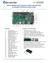
Basler dart daA2500-14lc camera, S-mount
Evetar lens M12B0816W ƒ/1.6, f8 mm, 1/2"
Processing board (Avnet MicroZed 7010 SoM)
Carrier board (Basler MicroZed BCON for LVDS carrier card)
microSD card (preinstalled with, e.g., Linux operating system, pylon
Camera Software Suite for Linux, FPGA image pipeline)
Flexible flat cable, 0.2 m
USB 2.0 cable (type A plug to Micro B plug), 1.8 m
GigE cable Cat 5e, 2.0 m
Power supply, 15 W, 5 V @ 3 A
International power cable plugs (see page 26 for details)
Mounting kit (including camera mounting plate, spacer bolts, screws,
and nuts)
This Quick Install Guide

10
HARDWARE INSTALLATION
HARDWARE INSTALLATION
Overview of the Components
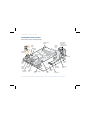
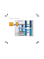
Fig. 1: Basler dart BCON for LVDS Development Kit – Installed Hardware Components
JP3
JP2
JP1
microSD
card slot
Reset
button
Boot mode
jumpers
USB-
UART
port
Processing
board
Carrier
board
dart BCON
for LVDS
camera with
S-mount lens
Power
Good
LED
Power
Good
LEDs
Flexible
flat cable
Power supply
port
GigE
port
USB 2.0
port
User
LED
Done
LED
Spacer
bolt
FFC
connector
Mounting
plate
FFC
connector

11
HARDWARE INSTALLATION
Installing the Basler dart BCON for LVDS Development Kit
Damage Hazard: Supplying power before the hardware installation is
completed can damage camera and board components.
Only connect the power supply to the mains socket after the hardware
installation is completed.
For the following installation steps, refer to Figure 1.
1. Attach four spacer bolts to the bottom of the mounting plate using four
screws (M2x4) included in the mounting kit.
2. Remove the protective caps from the lens and mount the lens on the
camera.
3. Attach the camera to the mounting plate using four screws (M2x12) so
that the lens is led through the hole of the plate. Fix the screws with the
nuts.
4. Lead the flexible flat cable through the rectangular cutout of the
mounting plate.
NOTICE
Note: When installing the development kit, Basler recommends that you
attach the camera to the included mounting plate. In this case, proceed
as described in the following procedure, where the lens is led through
the round hole of the plate.

12
HARDWARE INSTALLATION
5. Connect the flexible flat cable to the camera.
To insert the cable:
a. Push the end of the cable firmly into the FFC connector with the
ground tab facing down until the retaining tabs slide into the
recesses on both sides.
b. Flip the locking bar down to lock the FFC connector.
6. Mount the mounting plate on the carrier board using four screws
(M2x4).
7. Connect the flexible flat cable to the FFC connector on the carrier
board. Flex the cable and pass it through the second cutout of the
mounting plate.
8. Insert the microSD card carefully into the microSD card slot of the
processing board.
9. Connect the processing board to the carrier board by carefully pushing
the processing board’s MicroHeader connectors JX1 and JX2 into the
corresponding X10 and X7 connectors of the carrier board
(see also Figure 4).
10. Set the boot mode jumpers as follows:
JP3: bottom position
JP2: bottom position
JP1: top position
JP3 JP2 JP1

13
HARDWARE INSTALLATION
11. Connect the power supply to the carrier board and to the mains socket.
The board boots up.
12. Check that the following LEDs are lit.
On the carrier board:
4 Power Good LEDs (green)
On the processing board:
1 Power Good LED (green)
1 Done LED (blue)
1 User LED (red) - lights up only shortly
13. Connect the interface cables (Ethernet and USB).
Note: Basler strongly recommends not using the USB 2.0 port of the
processing board to operate a USB device (e.g., a camera) that requires
a power supply as specified by the USB 2.0 standard. When connected
to the USB 2.0 port, functionality and data transmission of the device
will be limited or the device will not be recognized at all.
For more information about enabling full USB 2.0 support, refer to
www.baslerweb.com or www.imaginghub.com.

14
ACQUIRING YOUR FIRST IMAGES
ACQUIRING YOUR FIRST IMAGES
Prerequisites
You have completed the hardware installation procedure as described in
the Hardware Installation chapter.
You have administrator rights for the computer.
The processing board is connected to a DHCP-enabled network, so that
the device can obtain an IP address automatically.
If you don't use a DHCP-enabled network, you can manually assign a
static IP address to the processing board and to the host computer.
Note: In the following steps, it is assumed that a Windows operating
system is installed on the host computer which will be used to connect
to the processing board. However, you can also use other operating
systems (e.g., Linux) on the host computer.

15
ACQUIRING YOUR FIRST IMAGES
Step 1: Installing the Required Software on the Host Computer
1. Download and install the "Silicon Labs CP210x USB to UART Bridge VCP
Driver" from the Silicon Labs website:
www.silabs.com/products/mcu/pages/usbtouartbridgevcpdrivers.aspx
For more information, see the Silicon Labs CP210x USB-to-UART Setup
Guide. You can download the document from www.microzed.org.
2. Download and install a terminal client.
In the following steps, the PuTTY terminal client is used. You can
download PuTTY from www.putty.org.
Step 2: Connecting to the Processing Board via Terminal
1. In Windows, open the Device Manager.
(Quick access: Win+R > type devmgmt.msc > Enter)
2. In the Device Manager, expand the Ports (COM & LPT) entry.
3. Determine which COM port the "Silicon Labs CP210x USB to UART
Bridge" device is connected to, e.g., COM3.

16
ACQUIRING YOUR FIRST IMAGES
4. Start your terminal client.
If you use PuTTY, the Session category opens.
5. In the Specify the destination you want to connect to group, click
Serial.
6. Click the Serial category and make the following settings.
In the Select a serial line group:
Serial line to connect to: type the COM port the "Silicon Labs
CP210x USB to UART Bridge" device is connected to, e.g., COM3.
In the Configure the serial line group:
Speed (baud): 115200
Data bits: 8
Stop bits: 1
Parity: None
Flow control: None

17
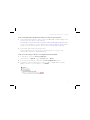
ACQUIRING YOUR FIRST IMAGES
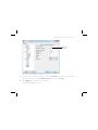
Fig. 2: PuTTY Configuration - Serial Line Settings
7. To save your serial line settings, click the Session category, enter a name
for your session in the Saved Sessions box and click Save.
8. Click Open to connect to the device.
A terminal window opens.
Determined
COM port

18
ACQUIRING YOUR FIRST IMAGES
9. On the processing board, press and release the Reset button
(see Figure 1).
The processing board reboots. Bootstrap messages are being displayed
in the terminal window.
Step 3: Changing the Processing Board’s MAC Address
When using the processing board's default factory configuration, a problem
arises from the fact that all units are set up to use the same Ethernet MAC
address. The resulting address collision must be avoided by changing the
MAC addresses of all boards.
1. Choose a set of different MAC addresses to use, one for each board.
Basler recommends choosing addresses from the "locally administered"
address range. For details, see
https://en.wikipedia.org/wiki/MAC_address#Universal_vs._local.
2. Make sure you are connected to the processing board via terminal (see
"Step 2: Connecting to the Processing Board via Terminal" on page 15).
3. On the processing board, press and release the Reset button
(see Figure 1).
Note: Step 3 only applies if you intend to operate multiple processing
boards connected to the same network.

19
ACQUIRING YOUR FIRST IMAGES
4. When the message Hit any key to stop autoboot appears in the
terminal window, press any key.
5. Assuming you have chosen a MAC address of 06:00:00:00:01:02 in
step 1:
Type setenv ethaddr 06:00:00:00:01:02 and press Enter.
6. Type saveenv and press Enter.
The new MAC address is now assigned to the processing board until it is
changed by this procedure again.
7. Press and release the Reset button for the changes to take effect.
8. Repeat steps 2 to 7 for each board that you want to connect to the
same network.
Step 4: Determining the Processing Board’s IP Address
1. Make sure you are connected to the processing board via terminal
(see "Step 2: Connecting to the Processing Board via Terminal" on
page 15).
2. On the processing board, press and release the Reset button
(see Figure 1).
3. When the message Hit any key to stop autoboot appears in the
terminal window, do not press any key and allow the countdown to
expire.

20
ACQUIRING YOUR FIRST IMAGES
4. When prompted, enter the following login credentials and press Enter:
zynq login: ubuntu
Password: ubuntu
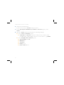
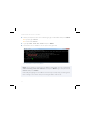
5. Type ip addr show dev eth0 and press Enter.
6. Determine the IP address of the processing board.
Fig. 3: IP Address of Processing Board
Note: If you want to assign the IP address manually, use the command
sudo ifconfig eth0 <IP address> and press Enter. Type the password
ubuntu and press Enter.
Manually assigning the IP address in this way is temporary, meaning that
this setting is lost when the processing board is rebooted.
Page is loading ...
Page is loading ...
Page is loading ...
Page is loading ...
Page is loading ...
Page is loading ...
Page is loading ...
Page is loading ...
Page is loading ...
Page is loading ...
Page is loading ...
Page is loading ...
-
 1
1
-
 2
2
-
 3
3
-
 4
4
-
 5
5
-
 6
6
-
 7
7
-
 8
8
-
 9
9
-
 10
10
-
 11
11
-
 12
12
-
 13
13
-
 14
14
-
 15
15
-
 16
16
-
 17
17
-
 18
18
-
 19
19
-
 20
20
-
 21
21
-
 22
22
-
 23
23
-
 24
24
-
 25
25
-
 26
26
-
 27
27
-
 28
28
-
 29
29
-
 30
30
-
 31
31
-
 32
32


Ask a question and I''ll find the answer in the document
Finding information in a document is now easier with AI
Related papers
-
Basler dart BCON for LVDS Owner's manual
-
-
-
-
-
-
-
-
Basler acA3800-14 User manual
-
Other documents
-
 Propel RC DART 1.0 Operating instructions
-
AVNET AES-Z7MB-7Z020-SOM-G/REV-H User manual
-
ICOM CS-9700 Installation guide
-
AVNET Xilinx XRF8 User manual
-
Sharper Image Glow-in-the-Dark Dart Blaster Owner's manual
-
Sierra Wireless 300 User manual
-
Microscan PanelScan PCB Traceability System User manual
-
Digilent Arty Z7 Reference guide
-
 Variscite DART-MX8M-PLUS User guide
-
Analog Devices AD9083 User guide

