Page is loading ...

REV 002A
ANTI-ROLL GYRO STABILIZER
INSTALLATION AND USE MANUAL EN page 3
MARCH 2020

PAGE INTENTIONALLY BLANK

EN
REV 002A
Quick
®
reserves the right to introduce changes to the equipment and the contents of this manual without prior notice.
In case of discordance or errors in translation between the translated version and the original text in the Italian language, reference will be made to the Italian text.
INSTALLATION AND USE MANUAL QUICK MC²X19 - REV002A
ANTI-ROLL GYRO STABILIZER
INSTALLATION AND USE MANUAL

4
EN
INSTALLATION AND USE MANUAL QUICK MC² X19 REV002A
Premise
STABILIZATION PRINCIPLES
The stability of a boat is inuenced by several factors, such as the hull shape, the displacement, the mass distribution, the
gyro installation position and sea conditions.
What is rolling?
Rolling is the oscillationof the boat around its longitudinal axis. Since vessels are much longer than larger, as a consequence-
side oscillation scan be felt much more.
The rolling motion is the most dangerous since it affects the vessel stability and it’s there for ethe one on which the rst
reduction studies have been carried out. More overside rolling is the main cause of sea sickness, especially in case of long
waves.
THE CORE OF BOAT’S STABILITY CONCEPT
In order to stabilize a boat, its center of gravity must be under the meta centre. In fact, the higher is its metacentrich eight,
the more stable is the boat.
THE CENTRE OF THRUST
BEFORE TALKING ABOUT STABILITY, WE NEED TO UNDERSTAND HOW THE THRUST’S CENTRE MOVES, ESPECIALLY DURING THE
ROLLING MOTION.
At equilibrium, the weight of the boat applies on (G), the Archimedes thrust applies on (C).
Throughout the rolling motion, the hull turns and the centre of thrust (C) constantly moves. Crossing the buoyancy force’s
line of action with the longitudinal plane of symmetry, we can find a new point called metacentre (M), located above the cen-
tre of gravity.
The distance between centre of gravity (G) and the metacentre (M) is called metacentric height (GM) which is very important
for a boat’s stability, since it represents the righting lever.
HOW A QUICK GYRO STABILIZER IS MADE
Quick MC2 gyro stabilizer has been designed for all typesof boats, with the goal of improving on board comfort level by redu-
cing the roll amplitude in presence of waves.
Gyroscopic stabilization takes place when a y wheel, rotating around its rotation axis, due to external causes (boat rolling)
also rotates around it sprecession axis, perpendicular to the rst, thus generating a stabilizing torque (gyroscopic effect).
The gyrostabilizer the refore opposes to the rolling movement by applying a stabilizing torque which opposes to the heeling
torque originated from the waves.

5
EN
INSTALLATION AND USE MANUAL QUICK MC² X19 REV002A
Premise
THE CONCEPT OF ONBOARD COMFORT
The onboard comfort is affected by «motion sickness» or sea sickness in case of boats. This sickness results from and is
amplied by specic conditions such as vibrations (like propulsion’s, engines’ etc), smells (such as fuel oil or diesel) and most
of all by accelerations.Accelerations onboard result from the vertical and side motion of the boat, especially pitching motion
(on which we can’t take any action) and rolling motion (objective of the gyro stabilizer).
ROLL
ACCELERATION
COMFORT
ROLL CORNER WIDTH
ROLL FREQUENCY
ROLL FREQUENCY:
Number of oscillations over time
ROLL CORNER WIDTH:
Inclination value of the boat's axis
ROLL ACCELERATION
Speed return of the initial boat position

PAGE INTENTIONALLY BLANK

7
EN
INSTALLATION AND USE MANUAL QUICK MC² X19 REV002A
INDEX
Standard equipment and required accessories Pag. 10
Premise Pag. 4
Stabilization principles Pag. 4
The core of boat's stability concept Pag. 4
The centre of thrust Pag. 4
How a quick gyro stabilizer made Pag. 4
The concept of onboard comfort Pag. 5
1 - Information about the product Pag. 8
1.0 - Description Pag. 8
1.2 - Technical data Pag. 8
1.4 - Dimensions Pag. 9
1.5 - Dimensions with base plate (optional) Pag. 9
2 - Supplied parts Pag. 11
2.0 - Package contains the following parts Pag. 11
2.1 - Required accessory, not supplied with the stabilizer Pag. 11
2.2 - Required components, not supplied with the stabilizer Pag. 11
2.3 - Tools needed for installation Pag. 11
3 - Introduction Pag. 12
3.0 - General information Pag. 12
3.1 - Preliminary technical checks Pag. 12
4 - Safety Pag. 13
4.0 - Precautions Pag. 13
4.1 - Warnings Pag. 13
4.2 - Personal protection equipment (PPE) Pag. 14
4.3 - Stickers/labels on the stabilizer Pag. 14
4.4 - Cases Pag. 15
4.5 - Flywheel Rotation Pag. 15
4.6 - Air output Pag. 15
5 - Handling and Transportation Pag. 16
5.0 - General instructions and precautions Pag. 16
5.1 - Crate removal Pag. 16
5.2 - Lifting the stabilizer Pag. 17
6 - Housing Pag. 18
6.0 - Structure and housing analysis Pag. 18
6.1 - Environmental requirements Pag. 18
6.2 - Water line Pag. 18
6.3 - Installing a single stabilizer Pag. 19
6.4 - Installation of multiple units on the same boat Pag. 20
7 - Installation procedures Pag. 21
7.0 - Support structure Pag. 21
7.1 - Types of Underbody Pag. 21
7.2 - Warnings Pag. 21
7.3 - Planarity of installation Pag. 22
7.4 - Stabilizer securing Pag. 23
7.5 - Stabilizer securing with base plate (optional) Pag. 24
7.6 - Fiberglass Support - Example 1 Pag. 25
7.7 - Fiberglass Support - Example 2 Pag. 26
7.8 - Brachet - Example 3 Pag. 27
7.9 - Brachet - Example 4 Pag. 28
8 - Electrical connection Pag. 29
8.0 - Connection system devices Pag. 29
8.1 - Devices dimensions Pag. 30
8.2 - Connection diagram Pag. 31
8.3 - Driver and stabilizer connection Pag. 32
9 - Start-up Pag. 33
9.0 - Introduction Pag. 33
9.1 - Start-up instructions Pag. 33
10 - Maintenance Pag. 33
10.0 - Introduction Pag. 33
10.1 - Warnings Pag. 33
10.2 - Periodic maintenance Pag. 34
10.3 - Annual maintenance Pag. 35
10.4 - External Cleaning Pag. 35
11 - Scrapping and Disposing Pag. 36
11.0 - Scrapping Pag. 36
11.1 - Disposing Pag. 37
12 - Accessories Pag. 38
Remote Control Pag. 38
Remote Control Accessories Pag. 38

8
EN
INSTALLATION AND USE MANUAL QUICK MC² X19 REV002A
1 - Information about the product
1.0 - Description
The MC
2
series is the result of careful research, aimed at achieving highly competitive performances.
The Quick
®
research and development laboratories have revolutionized the MC
2
series’ concept of operation, by introducing
technical solutions capable of guaranteeing greater safety, more comfort and much higher performances.
The MC
2
series stabilizers are compact and functional.
Quick MC²X19 is useful and effective to improve comfort on board, but it does not eliminate the risks deriving
from harsh atmospheric conditions.
1.1 - Main features
• Maximum performance
• Maximum protection
• Smart and compact design
• High installation exibility
• Dynamic precession control
• Precession lock function from remote panel.
• Equipped with Quick
®
electric motors.
• Low noise emission.
• Overheating protection.
• Thermal protection.
• MC
2
Mobile App to record stabilizer performance (iOS and Andorid)
• Reduced maintenance
1.2 - Technical data
(1) Rated speed: flywheel speed (RPM: Revolutions per minute).
(2) Angular momentum: it quantifies the torque that is necessary to balance the system in the time unit (Newtons meter second).
(3) Output torque: torque generated by the rotor at rated speed (Newtons per meter).
MODEL MC2 X19 MC2 X19 LV
Rated speed (1) 5300 RPM 5300 RPM
Angular momentum (2) 6090 N·m·s 6090 N·m·s
Output torque (3) 18700 N·m 18700 N·m
Spool-up time to rated RPM 43 min 43 min
Spool-up time to stabilization 35 min 35 min
Power absorbed 3500 W max 3500 W max
AC Input voltage 200-240 Vac 90-120 Vac
Frequency 50-60 Hz 50-60 Hz
Noise output < 70 dB < 70 dB
Ambient air temperature
from -10°C to +55°C
(14° F - 131° F)
from -10°C to +55°C
(14° F - 131° F)
Weight 553 kg (1219 lb) 553 kg (1219 lb)

9
EN
INSTALLATION AND USE MANUAL QUICK MC² X19 REV002A
1 - Information about the product
1.5 Dimensions with base plate (optional)
1.4 Dimensions
1.3 - Power Absorbtion
MODEL MC²
POWER ABSORBED
[W]
220V
AMPERE
1F [A]
CIRCUIT BRAKER
[A]
X19
3500 15,2 16
MODEL MC²
POWER ABSORBED
[W]
110V
AMPERE
1F [A]
CIRCUIT BRAKER
[A]
X19 LV
3500 30,4 32
610 (24
1/64
)
610 (24
1/64
)
677 (25
23/32
)
590 (23
9/32
)
590 (23
9/32
)
657 (25
29/32
)
610 (24
1/64
)
610 (24
1/64
)
677 (25
23/32
)
590 (23
9/32
)
590 (23
9/32
)
657 (25
29/32
)
1000W
2000W
3000W
4000W
5000W
6000W
7000W
0
0
8000W
10 min
50 min 60 min40 min30 min
T
20 min
35 min
3500W

10
EN
INSTALLATION AND USE MANUAL QUICK MC² X19 REV002A
Standard Equipment Kit
RC Remote Control MC
2
J3 RC Extension cable
CAN BUS 12 m
Connector cable
CAN T 5P F/F/F
CAN
Terminator
RC REMOTE CONTROL MC
2
touch - 5" - IP66
CAN BUS adapter cable (1 m / 3,28 ft)
Material included in the stabilizer’s packaging
Needed accessory and material included in its packaging
Not supplied with the stabilizer
Prewired
MC
²
X19 stabilizer
Screw
base plate (optional)
AC DYNAMIC CONTROL MC
2
Driver
Power cable 6 m
stabilizer → driver
J1 Extention CAN BUS 6 m
J2 Extention CAN BUS 6 m
J5 Extention CAN BUS 6 m
stabilizer → driver

11
EN
INSTALLATION AND USE MANUAL QUICK MC² X19 REV002A
2 - Supplied parts
MC
2
Quick gyro stabilizer is equipped with all the parts needed for its installation.
2.0 - Package contains the following parts
1 Pre-wired MC
2
X19 Gyro stabilizer
1 Power cable (6 m long)
1 AC DYNAMIC CONTROL MC
2
Driver to control and operate the gyro
1 J1 Extention CAN BUS (6 m long)
1 J2 Extention CAN BUS (6 m long)
1 J5 Extention CAN BUS (6 m long)
4 Eye bolts for MC
2
X19 stabilizer lifting
1 Template to install the MC
2
X19 stabilizer
Screws with resistance category higher than 10.9 (Grade 8). Tightening torque 136 Nm (1203.7 lbf/inch) - M12
1 Template to install the AC DYNAMIC CONTROL MC
2
driver
INSTALLATION AND USE MANUAL
The warranty
2.1 - Needed accessory and material included in its packaging
Not supplied with the stabilizer
• RC Remote Control MC
2
touch 5", IP66 - It allows you to turn the stabilizer on and off
and monitor its status ( also in multi-station).
Supplied with:
- template for mounting the Remote Control
- J3 RC Extention CAN BUS for the CAN BUS connection to the RC Remote Control MC
2
- CAN 5P T F/F/F connector
- CAN Terminator.
2.2 - Required components, not supplied with the stabilizer
• Differential circuit breaker for connecting the AC DYNAMIC CONTROL driver.
2.3 - Tools needed for installation
• Lifting straps
• Torque wrench
• Drill & drill bit 11 mm (7/16")
• Fork key 17 mm (21/32")
• Hexagonal key 8 mm (5/16")

12
EN
INSTALLATION AND USE MANUAL QUICK MC² X19 REV002A
3 - Introduction
Load generated by MC²X19
To calculate the structure sizing load use a safety factor (R = 3)
18700 N·m X 3 = 56100 N·m
(1Kg = 9,81 N·m)
3.1 - Preliminary technical checks
Before proceeding to the installation, it is essential to make sure that the position chosen and the boat structure
can withstand and enable the transfer of the loads generated by the gyroscope on the hull.
This document contains the instructions that are necessary for boat manufacturers and marine equipment installers to
assemble and commission the Quick
®
MC² gyro stabilizer.
3.0 - General information
Quick stabilizers have been designed for fixed installations in a protected space.
Taking into account the wide range of hulls and types of boats, the installer shall be responsible for building a solid
base that makes the stabilizer an integral part of the boat structure.
Nonetheless, Quick
®
is providing below some purely indicative illustrations that could be useful (See section 6.0).
The stabilizer’s installation and following inspection and repair operations must be performed exclusively by qualified
personnel.
The installer shall be responsible for the correct mechanical fixing, for the correct electrical connection, as well as for the
effective stabilizer operation after its installation on the boat.
This device must not be used by people (including children) with reduced physical, sensory or mental abilities.
QUICK
®
SpA will not accept responsibility for direct or indirect damages caused by improper use of the equipment.
BEFORE PROCEEDING TO THE STABILIZER'S INSTALLATION, ALL THE PROCEDURES
DESCRIBED AND ILLUSTRATED IN THIS INSTALLATION MANUAL MUST BE CAREFULLY
READ AND CORRECTLY UNDERSTOOD.
IF IN DOUBT, IMMEDIATELY CONTACT YOUR NEAREST AUTHORISED QUICK
®
DEALER.
If the installer do not able to guarantee that the boat structure is
able to withstand and transfer the loads in the hull generated by
the gyroscope, a qualified technician or a naval engineer should
intervene in order to carry out a suitable structural analysis on site.
The supporting base must be properly dimensioned in order to
withstand the declared stabilizing torque (Nm).
By sharing the total stabilizing torque on the three drections for
each fixing screw (8 screws), the following torque will result on each
dimension:
• Fz: 33 kN
• Fx: 21 kN
• Fy: 3 kN
The above-mentioned efforts must be considered to work
simultaneously.
These efforts don’t include voltages introduced by marine efforts
during navigation.
with base plate (optional)
+Fz
+Fx
-Fz
-Fy
-Fx
+Fz
+Fy
-Fy
+Fx
-Fz
-Fx
+Fy

13
EN
INSTALLATION AND USE MANUAL QUICK MC² X19 REV002A
4 - Safety
4.1 - Warnings
• The stabilizer operates within 200÷240 VAC power supply and LV version 90÷120 VAC
Connect to the electrical line in compliance with the protection standards in force.
The stabilizer motor frame must be properly grounded in order to guarantee the necessary protection in
case of indirect contact.
• While navigating, if the stabilizer rotates at its maximum speed, NOT to disconnect the power supply, in
order to avoid interrupting the gyroscope precession motion control.
• Secure the stabilizer to the boat structure by means of screws/nuts with strength class no less than 10.9.
• For tightening, use a torque wrench with the torque indicated by the manufacturer (see section 7.4 and 7.5)
DUE TO THE EXTREMELY HIGH ROTATION SPEED OF STABILIZERS, INSTALLERS AND USERS MUST STRICTLY
COMPLY WITH THE FOLLOWING WARNINGS:
• Activate the stabilizer only after having installed it correctly.
• Activate the stabilizer with the protection devices inserted
• Do NOT touch the stabilizer while it is running to prevent the danger of getting seriously
injured and damaging the gyroscope.
• Do NOT remove the external cover.
• Do NOT place any object, hands or body near the rotation area.
• Do NOT introduce extraneous objects inside the protection cover.
* Disconnect the stabilizer from the power supply and make sure that the flywheel has
stopped completely before performing any operation (
see info on display RC), such as cleaning or a simple inspection,
in order to prevent any damage to people or objects caused by an accidental start-up.
* Restore the power supply only after having correctly installed all
the safety devices that were removed to carry out the operations.
* Do NOT perform any type of electrical maintenance on any system device while
the stabilizer is disconnected from the power supply and the FLYWHEEL IS STILL ROTATING,
as its force continues to generate current.
* CLEANING THE APPLIANCE
• Do NOT use solvents or fuels to clean the appliance.
• Do NOT remove the safety labels on the equipment.
4.0 - Precautions
• Comply with all the safety warnings included in this manual.
• Comply with all the technical parameters indicated in this manual.
• The stabilizer must be lifted only by means of the lifting straps
properly secured to the supports on the base of the product.
• Handle with care paying attention to avoid damaging the gyro or getting injured.
• Strictly observe all the local accident prevention standards during both
assembling and regular operation.
• The work area shall be large enough to enable technicians
to assemble/disassemble the stabilizer.
• The stabilizer must be installed in a suitably ventilated place.
• Maximum cleanliness must be guaranteed during operations.
• Do not place any objects on the anti-roll stabilizer
• The environment where the stabilizer is installed must be dry and clean (no water, no splashes)
Further details on how to handle the appliance on section 5 of this manual.
*
WARNING: THIS OPERATION MUST BE CARRIED OUT BY QUICK AUTHORIZED
PERSONNEL ONLY. REMOVING THE COVERS AND SEALS WILL
VOID THE QUICK WARRANTY.

14
EN
INSTALLATION AND USE MANUAL QUICK MC² X19 REV002A
4 - Safety
4.2 - Personal protection equipment (PPE)
The personal protective equipment must comply with the national standards pertinent and must be checked, kept efficient
and used according to the manufacturer’s instructions.
PPE for the worker assigned to the installation and ordinary maintenance
Identification
pictogram
Description Notes
HELMET Protective helmet to prevent injuries caused by overhanging loads and knocks
against structures.
GLOVES Use of protective gloves to avoid cuts, punctures or pricks during operation.
SHOES Use of safety footwear to avoid damages caused by materials falling from a
height during stabilizer installation operations.
CLOTHES Use of suitable protective clothing to avoid it getting caught in moving or
transported parts.
EYEGLASSES Protect your eyes with eyeglasses or protecting screens in case of operations
near the hydraulic system in pressure.
4.3 - Stickers/labels on the stabilizer
On the stabilizer will be applied stickers/labels that report dangers and attention to be taken for the correct use.
Label pictogram Description Notes
DANGER DANGER OF CRUSHING HANDS AND FEET
DANGER RISK OF ROLLOVERING CRUSHING
CAUTION MOVING AND ROTATING EQUIPMENT

15
EN
INSTALLATION AND USE MANUAL QUICK MC² X19 REV002A
4 - Safety
FOR NO REASON REMOVE THE PROTECTION CASES
4.4 - Cases
4.5 - FLYWHEEL ROTATION
FLYWHEEL ROTATION:
Hourly or counterclockwise
bound to the verse of
stabilizer assembly
The direction of rotation
of the ywheel is
indicated by the label on
stabilizer cover
NON RIMUOVERE LE COVER DI PROTEZIONE
DO NOT REMOVE ANY PROTECTIVE COVERS
NE PAS RETIRER LE COUVERCLE DE PROTECTION
DIE SCHUTZABDECKUNG NICHT ENTFERNEN
NO QUITAR LA COBERTURA DE PROTECCIÓN
NON RIMUOVERE LE COVER DI PROTEZIONE
DO NOT REMOVE ANY PROTECTIVE COVERS
NE PAS RETIRER LES COUVERCLES DE PROTECTION
DIE SCHUTZABDECKUNG NICHT ENTFERNEN
NO QUITAR LAS TAPAS DE PROTECCIÓN
PACSMC2XR000
4.6 - Air output
AIR OUTPUT
The label will indicate the stabilizer air outlet area during operation.

16
EN
INSTALLATION AND USE MANUAL QUICK MC² X19 REV002A
5 - Handling and Transportation
5.0 - General instructions and precautions
The weight to be considered for lifting the MC² X19 stabilizer is 553 kg (1219 lb)
The stabilizer must be handled and transported by qualified personnel that can anchor the loads in compliance
with local safety regulations in the workplace.
• The stabilizer must be lifted by means of a suitable hoist, using the lifting straps properly secured to the supports
on the base.
• While removing the stabilizer from its packaging or while lifting it, it is necessary to work with caution, paying attention to
NOT cause damage to the equipment or allow it to hit the ground. Before installation on board, we recommend resting the
unit on a shockproof surface (e.g. wood, cardboard, cloth)
• Prevent electrical components from coming in contact with any surface or object, as this could damage such components.
• Do not scratch or cut on the painted finish that protects the stabilizer.
5.1 - Crate Removal
1. Remove the top cover of the crate.
2. Remove the side panels of the crate.
2.
1.

17
EN
INSTALLATION AND USE MANUAL QUICK MC² X19 REV002A
5 - Handling and Transportation
5.2 - Lifting the stabilizer
3. Lift the stabilizer with the straps properly secured to the supports on the base. Use spacers for ropes to prevent
damaging cables or connectors.
4. Lift the stabilizer, and remove the screws from the wood base on which the stabilizer is fixed.
NEVER LIFT THE STABILIZER INTO THE CONDITION IN EXAMPLE 5.
3.
5.
4.

18
EN
INSTALLATION AND USE MANUAL QUICK MC² X19 REV002A
6 - Housing
6.1 - Environmental requirements
• We recommend positioning the stabilizer in a dry, ventilated place in order to enable it to operate at full power and be
protected from atmospheric agents.
• Like for other machinery, for greater comfort we recommend choosing an engine compartment already fitted with acoustic
insulating material. The noise generated by MC
²
X19 is < 70 dB (measured in stable conditions, without wave motion).
• The work area shall be large enough to enable technicians to assemble/disassemble the stabilizer as well as having access
to it to maintenance.
To determine whether there is enough free space around the stabilizer, it is also necessary to make sure that there is enough
space to remove the external cover, to be able to access the connections, and to not obstruct other equipment nearby
6.0 - Structure and housing analysis
Before any assessment on the ideal location, it is necessary to make sure that the position chosen and the boat
structure are suitable to withstand and transfer to the hull the loads generated by the gyroscope on the hull.
If the installer does not have the necessary skills to perform this type of check, a qualified technician or a naval engineer
should be consulted to conduct a structural analysis on site.
Upon request, 2D and 3D dimensional drawings can be provided to accurately assess the dimensions
The selection of the area and the position on the boat requires taking some aspects in consideration, which will be
illustrated in the sections below by means of rules and recommendations.
6.2 - Water line
The installation of the stabilizer must be carried out with the value of the inclination of the plane of the hull of ± 2 degrees
with respect to the water line.
+2
-2
+2
-2
water line
min
max
centrato
centrato
WARNING:
do not remove any protective covers while the
stabilizer is in motion. The flywheel will continue
spinning for 1 hour after switching power off.
Open the cover only after all moving parts have
completely stopped. Install the protective covers
before energizing the stabilizer.
ATTENZIONE:
non rimuovere la cover di protezione fino a quando
lo stabilizzatore è in movimento. Il moto del volano
può durare anche 1 ora dopo lo spegnimento del
motore. Aprire la cover solo quando lo stabilizzatore è
completamente fermo. Richiudere la cover prima di
accendere lo stabilizzatore.
ATTENTION:
ne pas retirer le couvercle de protection tant que le
stabilisateur est en mouvement. Le mouvement du
volant peut durer jusqu’à 1 heure après l’extinction
du moteur. Ouvrir le couvercle uniquement lorsque
le stabilisateur est arrêté. Refermer le couvercle
avant d’allumer le stabilisateur.
ACHTUNG:
die Schutzabdeckung nicht entfernen, wenn sich der
Stabilisator in Bewegung befindet. Die Bewegung des
Schwungrades kan n auch 1 Stu nde nach d em
anhalten des Motors noch andauern.
Die Schu tzabde ckung ers
t öffnen , wen n de r
Stabilisator stillsteht. Die Schutzabdeckung vor dem
nächsten Start des Stabilisators wieder schliessen.
ATENCIÓN:
no quitar la cobertura de protección hasta que el
estabilizador esté en movimiento. El movimiento del
volante de inercia puede continuar durante 1 hora tras
apagar el motor. Abrir la cobertura solo cuando el
estabilizador esté parado.Volver a cerrar la cobertura
de protección antes de encender el estabilizador.
ROTATING PARTS!
DANGER
PALDMC2X1029
A
A =
B =
C =
D =
E =
B
D
E
C
210 mm
200 mm
200 mm
200 mm
200 mm

19
EN
INSTALLATION AND USE MANUAL QUICK MC² X19 REV002A
6 - Housing
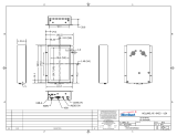
6.3 - Installing a single stabilizer
LThe installation of a single stabilizer can be done in any area of the boat, taking into account the following necessary
indications for the correct operation of the appliance:
• We recommend installing the stabilizer in the lower area of the hull, taking into account the available space and the
environmental requirements described in section 6.1.
• IMPORTANT: POSITION THE STABILIZER FOLLOWING THE INDICATIONS OF THE DRILLING TEMPLATE.
THE STICKER ON THE COVER (FLYWHEEL ROTATION) MUST BE POSITIONED TOWARDS THE STERN OR TOWARDS THE BOW.
ROTATING PARTS!
DANGER
ROTATING PARTS!
DANGER
centrato
centrato
ROTATING PARTS!
DANGER
ROTATING PARTS!
DANGER
centrato
centrato
ROTATING PARTS!
DANGER
ROTATING PARTS!
DANGER
centrato
centrato
100
4"
Descrizione / Description
Formato / Size
U.M. / M.U.
Disegnato da / Drawn by
Approvato da / Checked by
Scala / Scale
Foglio N°
This is an unpublished work the
copyright in which rest in Quick S.r.l.
All this document and its informa�on
is supplied without liability for error
or party may be reproduced used or
disclosed except as authorized by
contract or permission.
Data / Date
Via Piangipane 120/A - 48124 Piagipane (Ra)
DRILLING TEMPLATE
mm
Evitare di rilevare le quote dal disegno / avoid obtaining measures from the drawing
A A
B B
C C
D D
E E
F F
G G
H H
J J
K K
L L
M M
12
12
11
11
10
10
9
9
8
8
7
7
6
6
5
5
4
4
3
3
2
2
1
1
05/07/2019
145,25
145,25145,25
390
390
419,50
419,50
145,25
WARNING
CHECK SCREWS AFTER 50H OF USE
WARNING
USE ONLY WASHER AND LOCTITE
(DO NOT USE LOCK WASHER)
Ø 11 - Screws M10
n°8 - minimum strength class 10.9
39 Nm Tighten
HULL STRUCTURE MUST BE MORE PLANAR POSSIBLE
(NOT OVER 1.5MM FROM ON SIDE TO OTHER SIDE)
TIGHT SCREWS AT CORRECT
TIGHTENING TORQUE (SEE IN MANUAL)
WARNING
WARNING
USE ONLY THE SCREW PROVIDED BY QUICK
(OR SAME GRADE SCREWS)
WARNING
x2_x3
ROTATING PARTS!
DANGER
ROTATING PARTS!
DANGER
centrato
centrato
ROTATING PARTS!
DANGER
ROTATING PARTS!
DANGER
centrato
centrato
The bottom area of the
hull is recommended
The bottom area of the
hull is recommended
Free choice of the position
in the area available
Free choice of the position
in the area available
FLYWHEEL ROTATION:
Hourly or counterclockwise bound
to the verse of stabilizer assembly
The direction of rotation:
of the ywheel is indicated
by the label on stabilizer cover
HULL TYPE HARD CHINE
HULL TYPE ROUND BILGE
DRILLING
TEMPLATE
BOW
STERN

20
EN
INSTALLATION AND USE MANUAL QUICK MC² X19 REV002A
6.4 - Installation of multiple units on the same boat
The installation of multiple stabilizers on the same boat can be done taking into account the following necessary
requirements for correct operation:
• We recommend installing the stabilizers in the lower area of the hull, taking into account the available space and the
environmental requirements described in section 6.1.
• IMPORTANT: POSITION THE STABILIZER FOLLOWING THE INDICATIONS OF THE DRILLING TEMPLATE.
THE STICKER ON THE COVER (FLYWHEEL ROTATION) MUST BE POSITIONED TOWARDS THE STERN OR TOWARDS THE BOW.
• For the installation of several units, position the stabilizers so that the rotations of the flywheels are opposite.
6 - Housing
ROTATING PARTS!
DANGER
ROTATING PARTS!
DANGER
centrato
centrato
100
4"
Descrizione / Description
Formato / Size
U.M. / M.U.
Disegnato da / Drawn by
Approvato da / Checked by
Scala / Scale
Foglio N°
This is an unpublished work the
copyright in which rest in Quick S.r.l.
All this document and its informa�on
is supplied without liability for error
or party may be reproduced used or
disclosed except as authorized by
contract or permission.
Data / Date
Via Piangipane 120/A - 48124 Piagipane (Ra)
DRILLING TEMPLATE
mm
Evitare di rilevare le quote dal disegno / avoid obtaining measures from the drawing
A A
B B
C C
D D
E E
F F
G G
H H
J J
K K
L L
M M
12
12
11
11
10
10
9
9
8
8
7
7
6
6
5
5
4
4
3
3
2
2
1
1
05/07/2019
145,25
145,25145,25
390
390
419,50
419,50
145,25
WARNING
CHECK SCREWS AFTER 50H OF USE
WARNING
USE ONLY WASHER AND LOCTITE
(DO NOT USE LOCK WASHER)
Ø 11 - Screws M10
n°8 - minimum strength class 10.9
39 Nm Tighten
HULL STRUCTURE MUST BE MORE PLANAR POSSIBLE
(NOT OVER 1.5MM FROM ON SIDE TO OTHER SIDE)
TIGHT SCREWS AT CORRECT
TIGHTENING TORQUE (SEE IN MANUAL)
WARNING
WARNING
USE ONLY THE SCREW PROVIDED BY QUICK
(OR SAME GRADE SCREWS)
WARNING
x2_x3
LIMIT
LONGITUDINAL
DRILLING TEMPLATE
FLYWHEEL ROTATION:
Hourly or counterclockwise bound to the verse of
stabilizer assembly
The direction of rotation:
of the ywheel is indicated by
the label on stabilizer cover
HULL TYPE HARD CHINE
HULL TYPE ROUND BILGE
/