Page is loading ...

Part No. 8653-122 Iss. B 0816
5
1
INSTALLATION INSTRUCTIONS
1a
OUTSIDE
VIEW
“E”
“I”
1b
OUTSIDE
VIEW
“I”
“E”
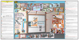
Ascertain the desired handing configurations required
Click the required handed plate and pull handles together
Install external (E) and internal (I) operating levers
Select and install restrictor plate (LH or RH) to external side
Secure furniture plates to door section using 25mm screws and plugs provided
Left Hand door application shown below for reference:
Right Hand door application shown below for reference:
Click together the Internal
Escutcheon Plate and the
Pull Handle, before
securing to the door
Click together the External
Escutcheon Plate and the
Pull Handle, before
securing to the door
Restrictor
plate to
External Side
Click together the Internal
Escutcheon Plate and the
Pull Handle, before
securing to the door
Click together the External
Escutcheon Plate and the
Pull Handle, before
securing to the door
Restrictor
plate to
External Side
LOCKWOOD 8653 SECURITY
SLIDING 3 POINT DOOR LOCK

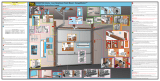
With the cylinder assembled, insert the key and rotate to the unlocked position.
Insert striker into lock body to test operation.
For the main lock drill two Ø3mm
holes and fit to door jamb where
marked using 12mm countersunk screws.
Adjust striker to correct position and
then tighten screws. For timber
jambs, use longer 10g screws provided.
Repeat the process with the top and bottom
strikers using the 8g screws provided.
Use larger
strikers on Top
and Bottom locks
Use smaller
striker on the
Main lock
Mounting the Striker
With the strikers inserted in the main lock body, and the top and
bottom locks, either mark the position on the outside of the
jamb or remove the backing from the tape and allow the strikers to
stick to the frame. Remove strikers from locks.
2
5
3
Position the cylinder assembly in the lock body so that the cam rotates towards
the front end of the door.
Secure with 32mm countersunk metal thread screw supplied.
Do not overtighten this screw, as it may jam the
locking mechanism.
4
Passage Mode
Rotate the key to put the lock into ‘Passage Mode’. Both handles will be free to operate.
Privacy Mode
Rotating the key 90° will place the lock into ‘Privacy Mode’. The external handle will
be locked and the internal handle, free to operate.
Alternatively, turn the internal handle towards the door jamb to place the
lock in Privacy Mode.
Deadlock Mode
Rotating the key 180° will place the lock into ‘Deadlock Mode’. Both the external
and internal handles will be locked, and the lock can only be unlocked by using the key.
PROWLER
PROOF
/