Page is loading ...

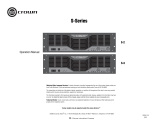
Operation Manual
CH1
Obtaining Other Language Versions:
To obtain information in another language about the use of this product, please contact your
local Crown Distributor. If you need assistance locating your local distributor, please contact Crown at 574-294-8000.
This manual does not include all of the details of design, production, or variations of the equipment. Nor does it cover every possible
situation which may arise during installation, operation or maintenance.
The information provided in this manual was deemed accurate as of the publication date. However, updates to this information may have
occurred.
To obtain the latest version of this manual, please visit the Crown website at www.crownaudio.com.
Trademark Notice:
Crown, Crown Audio, Amcron, and BCA are registered trademarks of Crown International. Other trademarks are
the property of their respective owners.
Some models may be exported under the name Amcron.
®
©2006 by Crown Audio
®
Inc., 1718 W. Mishawaka Rd., Elkhart, Indiana 46517-9439 U.S.A. Telephone: 574-294-8000
130808-8
1/06
CH and CL Series
CH2
CH4
CL1
CL2
CL4

Operation Manual
CH and CL Series Power Amplifiers
page 2
1) Read these instructions.
2) Keep these instructions.
3) Heed all warnings.
4) Follow all instructions.
5) Do not use this apparatus near water.
6) Clean only with a dry cloth.
7) Do not block any ventilation openings. Install
in accordance with the manufacturer’s instruc-
tions.
8) Do not install near any heat sources such as
radiators, heat registers, stoves, or other
apparatus (including amplifiers) that produce
heat.
9) Do not defeat the safety purpose of the polar-
ized or grounding-type plug. A polarized plug
has two blades with one wider than the other.
A grounding-type plug has two blades and a
third grounding prong. The wide blade or the
third prong is provided for your safety. If the
provided plug does not fit into your outlet,
consult an electrician for replacement of the
obsolete outlet.
10) Protect the power cord from being walked on
or pinched, particularly at plugs, convenience
receptacles, and the point where they exit from
the apparatus.
11) Only use attachments/accessories specified
by the manufacturer.
12) Use only with a cart, stand, tripod, bracket, or
table specified by the manufacturer, or sold
with the apparatus. When a cart is used, use
caution when moving the cart/apparatus com-
bination to avoid injury from tip-over.
13) Unplug this apparatus during lightning storms
or when unused for long periods of time.
14) Refer all servicing to qualified service person-
nel. Servicing is required when the apparatus
has been damaged in any way, such as power-
supply cord or plug is damaged, liquid has
been spilled or objects have fallen into the
apparatus, the apparatus has been exposed to
rain or moisture, does not operate normally,
or has been dropped.
15) WARNING: TO REDUCE THE RISK OF FIRE
OR ELECTRIC SHOCK, DO NOT EXPOSE
THIS APPARATUS TO RAIN OR MOISTURE.
16) DO NOT EXPOSE TO DRIPPING OR SPLASH-
ING. DO NOT PLACE OBJECTS FILLED WITH
LIQUID, SUCH AS VASES,ON THIS APPARA-
TUS.
TO PREVENT ELECTRIC SHOCK DO NOT REMOVE
TOP OR BOTTOM COVERS. NO USER SERVICE-
ABLE PARTS INSIDE. REFER SERVICING TO
QUALIFIED SERVICE PERSONNEL.
À PRÉVENIR LE CHOC ÉLECTRIQUE N’ENLEVEZ
PAS LES COUVERCLES. IL N’Y A PAS DES PAR-
TIES SERVICEABLE À L’INTÉRIEUR. TOUS REPA-
RATIONS DOIT ETRE FAIRE PAR PERSONNEL
QUALIFIÉ SEULMENT.
TO COMPLETELY DISCONNECT THIS EQUIPMENT
FROM THE AC MAINS, DISCONNECT THE POWER
SUPPLY CORD PLUG FROM THE AC RECEPTA-
CLE. THE MAINS PLUG OF THE POWER SUPPLY
CORD SHALL REMAIN READILY OPERABLE.
WATCH FOR THESE SYMBOLS:
The lightning bolt triangle is used to alert the user
to the risk of electric shock.
The exclamation point triangle is used to alert the
user to important operating or maintenance instruc-
tions.
Important Safety Instructions
FCC COMPLIANCE NOTICE
This device complies with part 15 of the FCC rules. Operation is subject to the following
two conditions: (1) This device may not cause harmful interference, and (2) this device
must accept any interference received, including interference that may cause undesired
operation.
CAUTION: Changes or modifications not expressly approved by the party responsible for
compliance could void the user’s authority to operate the equipment.
NOTE: This equipment has been tested and found to comply with the limits for a Class B
digital device, pursuant to part 15 of the FCC Rules. These limits are designed to provide
reasonable protection against harmful interference in a residential installation. This
equipment generates, uses, and can radiate radio frequency energy and, if not installed
and used in accordance with the instruction manual, may cause harmful interference to
radio communications. However, there is no guarantee that interference will not occur in a
particular installation. If this equipment does cause harmful interference to radio or televi-
sion reception, which can be determined by turning the equipment off and on, the user is
encouraged to try to correct the interference by one or more of the following measures:
• Reorient or relocate the receiving antenna.
• Increase the separation between the equipment and receiver.
• Connect the equipment into an outlet on a circuit different from that to which the
receiver is connected.
• Consult the dealer or an experienced radio/TV technician for help.
IMPORTANT
Commercial Audio Series amplifiers require Class 2
output wiring.
MAGNETIC FIELD
CAUTION! Do not locate sensitive high-gain equip-
ment such as preamplifiers or tape decks directly
above or below the unit. Because this amplifier has a
high power density, it has a strong magnetic field
which can induce hum into unshielded devices that
are located nearby. The field is strongest just above
and below the unit.
If an equipment rack is used, we recommend locat-
ing the amplifier(s) in the bottom of the rack and the
preamplifier or other sensitive equipment at the top.

page 3
CH and CL Series Power Amplifiers
Operation Manual
DECLARATION of CONFORMITY
Crown International, Inc.
Sue Whitfield
574-294-8289
European Representative's Name and Address:
Nick Owen
35, Bassets Field
Thornhill
Cardiff. South Glamorgen
CF14 9UG United Kingdom
Equipment Type: Commercial Audio Power Amplifiers
Family Name: CH Series, CL Series
Model Names: CH1, CH2, CH4, CL1, CL2, CL4
EMC Standards:
EN 55103-1:1995 Electromagnetic Compatibility - Product Family Standard for Audio, Video, Audio-Visual and Entertainment Lighting Control Apparatus for Professional Use, Part 1: Emissions
EN 55103-1:1995 Magnetic Field Emissions-Annex A @ 10 cm and 1 M
EN 61000-3-2:1995+A14:2000 Limits for Harmonic Current Emissions (equipment input current ≤16A per phase)
EN 61000-3-3:1995 Limitation of Voltage Fluctuations and Flicker in Low-Voltage Supply Systems Rated Current ≤16A
EN 55022:1992 + A1: 1995 & A2:1997 Limits and Methods of Measurement of Radio Disturbance Characteristics of ITE: Radiated, Class B Limits; Conducted, Class B
EN 55103-2:1996 Electromagnetic Compatibility - Product Family Standard for Audio, Video, Audio-Visual and Entertainment Lighting Control Apparatus for Professional Use, Part 2: Immunity
EN 61000-4-2:1995 Electrostatic Discharge Immunity (Environment E2-Criteria B, 4k V Contact, 8k V Air Discharge)
EN 61000-4-3:1996 Radiated, Radio-Frequency, Electromagnetic Immunity (Environment E2, criteria A)
EN 61000-4-4:1995 Electrical Fast Transient/Burst Immunity (Criteria B)
EN 61000-4-5:1995 Surge Immunity (Criteria B)
EN 61000-4-6:1996 Immunity to Conducted Disturbances Induced by Radio-Frequency Fields (Criteria A)
EN 61000-4-11:1994 Voltage Dips, Short Interruptions and Voltage Variation
Safety Standard:
EN 60065: 1998 Safety Requirements - Audio Video and Similar Electronic Apparatus
I certify that the product identified above conforms to the requirements of the EMC Council Directive 89/336/EEC as amended by 92/31/EEC, and the Low Voltage Directive 73/23/EES as amended by 93/68/EEC.
Larry Coburn
Signed
Title: Senior Vice President of Manufacturing
Issued By: Crown International, Inc.
1718 W. Mishawaka Road
Elkhart, Indiana 46517 U.S.A.
The following applies to the CH 1, CH 2, CL 1 and CL 2 only.
Due to line current harmonics, we recommend that you contact your supply authority before connection.
FOR COMPLIANCE QUESTIONS ONLY:

Operation Manual
CH and CL Series Power Amplifiers
page 4
Table of Contents
Important Safety Instructions .......................................................2
Declaration of Conformity ............................................................3
1 Welcome ..................................................... 5
1.1 Features ...........................................................................5
1.2 How to Use This Manual ..................................................5
2 Setup ......................................................... 6
2.1 Unpack Your Amplifier .....................................................6
2.2 Install Your Amplifier .......................................................6
2.3 Ensure Proper Cooling ....................................................6
2.4 Choose Input Wire and Connectors .................................7
2.5 Choose Output Wire and Connectors ...............................7
2.6 Switch Settings ................................................................8
2.7 Wire Your System ............................................................9
2.7.1 Models CH1 & CH2 Stereo Mode............................9
2.7.2 Models CH1 & CH2 140V Bridge Mode .................9
2.7.3 Model CH4 Stereo Mode ........................................10
2.7.4 Model CH4 Bridge Mode ........................................10
. 2.7.5 Models CL1 & CL2 Stereo Mode ............................11
2.7.6 Models CL1 & CL2 Bridge Mode ...........................11
. 2.7.7 Model CL4 Stereo Mode .........................................12
2.7.8 Model CL4 Bridge Mode ........................................12
2.7.9 All Models: How to Parallel the Inputs
in Stereo Mode........................................................13
2.8 Connect to AC Mains .......................................................13
2.9 Startup Procedure ............................................................13
3 Operation .................................................... 14
3.1 Precautions ......................................................................14
3.2 Indicators .........................................................................18
3.3 Controls ...........................................................................18
4 Advanced Features and Options .............................. 19
4.1 Protection Systems ..................................................................19
4.1.1 Power Circuit Breaker .....................................................19
4.1.2 Proportional-speed or 3-speed Fan ................................19
4.2 Advanced Features ..................................................................19
4.2.1 BCA
®
(CH4 and CL4 Only) .............................................19
4.2.2 Switching Power Supply with PFC (CH4 and CL4 Only) .19
4.3 Options .....................................................................................19
4.3.1 Input Sensitivity ...............................................................19
4.3.2 Crown SST Modules .......................................................19
4.3.3 Fault Monitoring ..............................................................21
4.3.4 Precision Detented Level Controls ...................................22
5 Principles of Operation ........................................ 23
5.1 CH1, CH2, CL1 and CL2 .........................................................23
5.2 CH4 and CL4 ...........................................................................25
5.2.1 Audio Signal Path ...........................................................25
5.2.2 Power Supply Operation .................................................27
6 Troubleshooting ................................................. 28
7 Specifications ................................................... 29
8 AC Power Draw and Thermal Dissipation ................... 34
9 Service ............................................................ 38
9.1 International and Canada Service ............................................38
9.2 US Service ...............................................................................38
9.2.1 Service at a US Service Center........................................38
9.2.2 Factory Service ...............................................................38
9.2.3 Factory Service Shipping Instructions: ...........................38
9.2.4 Packing Instructions........................................................38
9.2.5 Estimate Approval............................................................38
9.2.6 Payment of Non-Warranty Repairs...................................38
10 Warranty ......................................................... 39
Crown Factory Service Information Form ............................................41

page 5
CH and CL Series Power Amplifiers
Operation Manual
1 Welcome
Congratulations on your purchase of a Crown
®
CH or CL Series commercial power amplifier.
The CH and CL Series is a complete family of
amplifiers with a wide range of power output
capabilities and output configurations.
CH Series amplifiers can directly drive “con-
stant voltage” lines, so you can avoid the
expense of adding step-up transformers for
distributed loudspeaker systems. CL Series
amplifiers offer low-impedance compatibility
for applications where high-power, low-imped-
ance loads are the primary requirement.
All CH and CL Series amplifiers feature
Crown’s exclusive SST (System Solutions
Topologies) expansion system. The SST expan-
sion system makes it easy to tailor your ampli-
fier to a specific application or to add future
technology as it develops (see Section 4.3.2 for
descriptions of available SSTs).
Modern power amplifiers are sophisticated
pieces of engineering capable of producing
extremely high power levels. They must be
treated with respect and correctly installed if
they are to provide the many years of reliable
service for which they were designed.
In addition, CH and CL Series amplifiers
include a number of features which require
some explanation before they can be used to
their maximum advantage.
Please take the time to study this manual so
that you can obtain the best possible service
from your amplifier.
1.1 Features
• The CH and CL Series amplifiers are
designed specially for fixed installation,
and include the following features:
• CH Series provides for both low imped-
ance and high impedance loads, with the
choice of 4/8 ohm or 70V operation for
each channel. The output mode of each
channel can be set independently, allowing
unique or mismatched loads to be driven
by each channel.
• CH Series includes a 70-Hz high-pass fil-
ter for each channel (when used in 70V
mode) providing necessary low-frequency
roll-off to eliminate saturation of constant
voltage step-down transformers typically
used in 70V distributed systems.
• CL Series includes high power 2-ohm
operation, for jobs where low impedance is
the only requirement.
• A red five-way Fault LED for each channel
blinks during amplifier power-up, and
upon the following fault conditions: exces-
sive heatsink temperature; transformer
thermal protection; short at amplifier out-
put; output stage non-operational.
• An RJ11 connector allows external circuits
to monitor the status of the Fault circuit.
• Detented level controls are located on the
back panel for security, and allow for accu-
rate level settings.
• Barrier strip output connectors allow for
quick easy connection regardless of the
load, and accept up to 10 AWG crimp-on
terminal forks.
• SST modules provide flexible input
options, such as onboard crossover con-
figurations.
• Stereo/Bridge switch allows conversion
from Stereo mode to Bridge mode for
higher-powered single-channel operation.
• Advanced protection circuitry guards
against: shorted outputs, open circuits,
DC, mismatched loads, general overheat-
ing, high frequency overloads and internal
faults.
• Three Year, No-Fault, Fully-Transferable
Warranty completely protects your invest-
ment and guarantees its specifications.
1.2 How to Use This Manual
This manual provides you with the necessary
information to safely and correctly setup and
operate your amplifier. It does not cover every
aspect of installation, setup or operation that
might occur under every condition. For addi-
tional information, please consult Crown’s
Amplifier Application Guide (available online at
www.crownaudio.com), Crown Technical Sup-
port, your system installer or retailer.
We strongly recommend you read all instruc-
tions, warnings and cautions contained in this
manual. Also, for your protection, please send
in your warranty registration card today. And
save your bill of sale — it’s your official proof
of purchase.
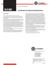
Output Power
Output Power at 1 kHz at rated THD; Stereo mode, per channel with both channels driven.
STEREO MODE BRIDGE MODE
2 Ohms 4 Ohms 8 Ohms 70V 4 Ohms 8 Ohms 140V
CH1 450W 275W 300W 900W 600W
CH2 660W 400W 600W 1320W 1200W
CH4 1400W 1200W 600W 1200W 2400W 2400W
CL1 560W 450W 275W 1100W 900W
CL2 975W 660W 400W 1950W 1320W
CL4 1800W* 1200W 600W 3600W* 2400W
* ≥ 200VAC Line Voltage
2800W
Output Power
Output Power at 1 kHz at rated THD; Stereo mode, per channel with both channels driven.
STEREO MODE
BRIDGE MODE

Operation Manual
CH and CL Series Power Amplifiers
page 6
2.1 Unpack Your Amplifier
Please unpack and inspect your amplifier for
any damage that may have occurred during
transit. If damage is found, notify the transpor-
tation company immediately. Only you can ini-
tiate a claim for shipping damage. Crown will
be happy to help as needed. Save the shipping
carton as evidence of damage for the shipper’s
inspection.
We also recommend that you save all packing
materials so you will have them if you ever
need to transport the unit. Never ship the
unit without the factory pack.
YOU WILL NEED (not supplied):
• Input wiring cables
• Output wiring cables
Rack for mounting amplifier (or a stable surface
for stacking)
WARNING: Before you start to set up
your amplifier, make sure you read and
observe the Important Safety Instruc-
tions found at the beginning of this
manual.
2.2 Install Your Amplifier
CAUTION: Before you begin, make sure
your amplifier is disconnected from the
power source, with the power switch in
the “off” position and all level controls
turned completely down (counterclock-
wise).
Use a standard 19-inch (48.3 cm) equipment
rack (EIA RS-310B). See Figure 2.1 for ampli-
fier dimensions.
You may also stack amps without using a
cabinet.
NOTE: When transporting, amplifiers should be
supported at both front and back.
2.3 Ensure Proper Cooling
When using an equipment rack, close any open
spaces in rack with blank panels. DO NOT
block front or rear air vents. The side walls of
the rack should be a minimum of two inches
(5.1 cm) away from the amplifier sides, and the
back of the rack should be a minimum of four
inches (10.2 cm) from the amplifier back panel.
For more information on cooling, please refer
to the Crown Amplifier Application Guide,
available online at www.crownaudio.com.
Figure 2.2 illustrates standard amplifier airflow.
2 Setup
Figure 2.1 Mounting Dimensions
Figure 2.2 Airflow

page 7
CH and CL Series Power Amplifiers
Operation Manual
2.4 Choose Input Wire
and Connectors
You have three choices of input connectors: 1/4-inch (6.35-mm)
phone, 3-pin XLR, or barrier strip. You can also use either bal-
anced or unbalanced wiring.
Figure 2.3 shows balanced connector pin assignments for XLR
and phone. Figure 2.4 shows unbalanced connector pin assign-
ments for XLR and phone.
Figure 2.5 shows barrier strip input wiring for a balanced signal.
Both channels should be wired using a common center terminal
for ground connection.
NOTE: Custom wiring should only be performed by
qualified personnel.
Figure 2.3 Balanced
Input Connector
Wiring
Figure 2.4 Unbalanced
Input Connector
Wiring
2 Setup
2.5 Choose Output Wire
and Connectors
Crown recommends using professionally constructed, high-
quality, two- or four-conductor, heavy gauge speaker wire and
connectors. You may use terminal forks or bare wire for your out-
put connectors (see Figure 2.7). CH and CL Series amplifier ter-
minal strips accept up to 10 AWG terminal forks which fit over a
#8 screw.
To prevent the possibility of short circuits, wrap or otherwise
insulate exposed loudspeaker cable and connectors. Also, a no-
touch cover, which covers the terminal strips, is provided to help
prevent short circuits. To remove this cover,
1. Loosen screws inside top and bottom holes of cover (see Fig-
ure 2.6).
2. Slide cover up or down, then pull it off away from the amplifier.
Using the guidelines below, select the appropriate size of wire
based on the distance from amplifier to speaker.
3. Reinstall no-touch cover to maintain safety.
CAUTION: Never use shielded cable for output wiring.
Distance Wire Size
up to 25 ft. 16 AWG
26-40 ft. 14 AWG
41-60 ft. 12 AWG
Over 60 ft. 10 AWG
Figure 2.7 CL Series and CH4 Output Connector Wiring
Figure 2.5 Barrier Strip Input Wiring:
Balanced Signal In
2. SLIDE then
PULL OFF
1. LOOSEN
SCREWS
Figure 2.6 How to
Remove the No-Touch
Cover

Operation Manual
CH and CL Series Power Amplifiers
page 8
2.6 Switch Settings
Proper wiring depends on how you configure
your amplifier. The CH and CL Series offer vari-
ous modes of operation:
• Constant-voltage load
• 4/8-ohm load
• Stereo mode
• Bridge-mono mode
Let’s explain each mode of operation
Each output channel can be independently con-
figured to drive either (1) 4/8-ohm loudspeak-
ers, or (2) step-down transformers in a
distributed “constant voltage” loudspeaker sys-
tem. “Constant voltage” refers to 70V operation
with models CH1, CH2 and CH4 only. Also, the
amplifier can be configured for Dual or Bridge
modes. Various combinations of these modes
are possible.
CH and CL Series amplifiers can be configured
for either Stereo (dual channel) or Bridge (sin-
gle mono channel) modes of operation. To
switch your amplifier accordingly, set the
recessed “Stereo/Bridge” switch to the desired
setting as shown in Figure 2.8.
CH Series amplifiers only: Select 4/8 ohm
or 70V operation as appropriate for your appli-
cation and your amplifier. Select output opera-
tion by sliding the recessed Output Operation
switches to the desired position as shown in
Figure 2.9.
When the CH Series amplifier is set up for two-
channel (Stereo mode) operation, it is possible
to configure the output channels for either 4/8
ohm or 70V operation.
WARNING: If Bridge mode is used with
70V output, the amplifier will actually
deliver 140 volts.
WARNING: The two Output Operation
switches must be set to identical posi-
tions (4/8 ohm or 70V mode) when oper-
ating in Bridge mode. Never change
switch positions with power turned on.
CAUTION: Output Terminals are acti-
vated by selection of an output opera-
tion mode via the Output Operation
switches. All other Output Terminals are
inactive. For example, when 4/8 Ohm Opera-
tion is selected, the 70V connections are inac-
tive, with no audio present at those Output
Terminals.
Figures 2.9 through 2.16 on the following
pages show common ways to install CH and CL
Series amplifiers in a sound system. Input and
output terminals are located on the back panel.
CAUTION: Always disconnect the AC
power and turn the level controls off
when making or breaking connections.
This is very important when loudspeakers are
connected because it reduces the chance of
loud blasts that can cause loudspeaker dam-
age.
CAUTION: Never tie an amplifier’s out-
puts together directly while in Stereo
mode. Never parallel them with the out-
put of another amplifier. Such connections
do not result in increased output power, but
may cause overheating and premature activa-
tion of the protection circuitry.
Note: The Channel 2 input jack and Input Level
control are not defeated in Bridge mode. A sig-
nal feeding Channel 2 will work against the
Channel 1 signal, and usually results in distor-
tion and inefficient operation.
2 Setup
Figure 2.8 Stereo/Bridge Mode Switch
Figure 2.9 Channel Operation Switches
CH1
4/8 VΩ70 4/8 VΩ70
CH2
Channel Operation
Model CH4
Models CH1 and CH2

page 9
CH and CL Series Power Amplifiers
Operation Manual
2.7 Wire Your System
2.7.1 Models CH1 & CH2 Stereo Mode
See Figure 2.10. In this example, Channel 1 is wired
to a 4/8 ohm load and Channel 2 is wired to a 70V
load.
Make sure the Mode switch is set to the “Stereo”
position. Set the Channel Operation Switch to
4/8 ohms on Channel1, and to 70V on Channel 2.
INPUTS: Connect input wiring for each channel.
OUTPUTS: Maintain proper polarity (+/–) on output
connectors.
• Connect Channel 1 positive speaker lead to
Channel 1 4/8 ohm output terminal.
• Connect Channel 1 negative speaker lead to
Channel 1 negative terminal.
• Connect Channel 2 positive transformer lead to
either of Channel 2 70V+ output terminals. (The two
70V screws are in parallel offering more wiring flexi-
bility).
• Connect Channel 2 negative transformer lead to
Channel 2 negative (–) terminal.
Refer to Section 2.5 for output connector pin assign-
ments.
2.7.2 Models CH1 & CH2 140V Bridge
Mode
See Figure 2.11. In this example, a 140V load is
connected in Bridge Mono across the 70V+ termi-
nals of Channel 1 and Channel 2. Both Channel
Operation Switches are set to 70V. Make sure the
Mode switch is set to the “Bridge” position.
NOTE: When operating in Bridge-Mono
mode, turn down (full CCW) the level control
for Channel 2, as the Channel-1 level control
works both channels.
INPUTS: Connect input wiring to Channel 1.
OUTPUTS: Connect positive (+) transformer lead to
Channel 1 70V+ output terminal. Connect negative
(–) transformer lead to Channel 2 70V+ output termi-
nal.
Refer to Section 2.5 for output connector pin assign-
ments.
2 Setup
Figure 2.10 Models CH1 & CH2 Wiring for Stereo Mode
(Shown with No-Touch Cover Removed)
Figure 2.11 Models CH1 & CH2 Wiring for 140V Bridge Mode
(Shown with No-Touch Cover Removed)
8 or 4 ohms
70 V

Operation Manual
CH and CL Series Power Amplifiers
page 10
Mixer
+
2.7.3 Model CH4 Stereo Mode
See Figure 2.12. In this example, Channel 1 is
wired to a 4/8 ohm load and Channel 2 is wired
to a 70V load.
Make sure the Mode switch is set to the “Stereo”
position. Set the Channel Operation Switch to
4/8 ohms on Channel1, and to 70V on Channel
2.
INPUTS: Connect input wiring for each channel.
OUTPUTS:
• Connect Channel 1 positive (+) speaker lead
to Channel 1 positive (+) terminal of amp.
• Connect Channel 1 negative (–) speaker lead
to Channel 1 negative (–) output terminal of
amp.
• Connect Channel 2 positive (+) transformer
lead to Channel 2 positive terminal of amp.
• Connect Channel 2 negative (–) transformer
lead to Channel 2 negative (–) output terminal of
amp.
Refer to Section 2.5 for output connector pin
assignments.
2.7.4 Model CH4 Bridge Mode
See Figure 2.13. In this example, a 4/8-ohm load
is connected in Bridge Mono across the positive
terminals of Channel 1 and Channel 2. Both
Channel Operation Switches are set to 4/8 ohms.
Make sure the Mode switch is set to the “Bridge”
position.
NOTE: When operating in Bridge-Mono
mode, turn down (full CCW) the level
control for Channel 2, as the Channel-1
level control works both channels.
INPUTS: Connect input wiring to Channel 1.
OUTPUTS: Connect positive (+) speaker lead to
Channel 1 positive (+) terminal of amp. Connect
negative (–) speaker lead to Channel 2 positive
(+) terminal of amp. Do not connect to negative
output terminals.
Refer to Section 2.5 for output connector pin
assignments.
2 Setup
Figure 2.12 Model CH4 Wiring for Stereo Mode
(Shown with No-Touch Cover Removed)
Figure 2.13 Model CH4 Wiring for Bridge Mode
(Shown with No-Touch Cover Removed)
8 or 4 ohms
70 V

page 11
CH and CL Series Power Amplifiers
Operation Manual
2.7.5. Models CL1 & CL2 Stereo
Mode
See Figure 2.14. In this example, Channel 1 and
Channel 2 are wired to 4/8-ohm speaker loads.
Make sure the Mode switch is set to the “Stereo”
position.
INPUTS: Connect input wiring for each channel.
OUTPUTS:
• Connect Channel 1 positive (+) speaker lead
to Channel 1 positive (+) terminal of amp.
• Connect Channel 1 negative (–) speaker lead
to Channel 1 negative (–) output terminal of
amp.
• Repeat similarly for Channel 2.
Refer to Section 2.5 for output connector pin
assignments.
2.7.6 Models CL1 & CL2 Bridge
Mode
See Figure 2.15. In this example, a 4/8-ohm load
is connected in Bridge Mono across the positive
terminals of Channel 1 and Channel 2. Make
sure the Mode switch is set to the “Bridge” posi-
tion.
NOTE: When operating in Bridge-Mono
mode, turn down (full CCW) the level
control for Channel 2, as the Channel-1
level control works both channels.
INPUTS: Connect input wiring to Channel 1.
OUTPUTS: Connect positive (+) speaker lead to
Channel 1 positive (+) terminal of amp. Connect
negative (–) speaker lead to Channel 2 positive
(+) terminal of amp. Do not connect to negative
output terminals.
Refer to Section 2.5 for output connector pin
assignments.
Figure 2.14 Models CL1 & CL2 Wiring for Stereo Mode
(Shown with No-Touch Cover Removed)
Figure 2.15 Models CL1 & CL2 Wiring for Bridge Mode
(Shown with No-Touch Cover Removed)
2 Setup
Mixer
Mixer

Operation Manual
CH and CL Series Power Amplifiers
page 12
2.7.7. Model CL4 Stereo Mode
See Figure 2.16. In this example, Channel 1 and
Channel 2 are wired to 4/8-ohm speaker loads.
Make sure the Mode switch is set to the “Stereo”
position.
INPUTS: Connect input wiring for each channel.
OUTPUTS:
• Connect Channel 1 positive (+) speaker lead
to Channel 1 positive (+) terminal of amp.
• Connect Channel 1 negative (–) speaker lead
to Channel 1 negative (–) output terminal of
amp.
• Repeat similarly for Channel 2.
Refer to Section 2.5 for output connector pin
assignments.
2.7.8 Model CL4 Bridge Mode
See Figure 2.17. In this example, a 4/8-ohm load
is connected in Bridge Mono across the positive
terminals of Channel 1 and Channel 2. Make
sure the Mode switch is set to the “Bridge” posi-
tion.
NOTE: When operating in Bridge-Mono
mode, turn down (full CCW) the level
control for Channel 2, as the Channel-1
level control works both channels.
INPUTS: Connect input wiring to CH1.
OUTPUTS: Connect positive (+) speaker lead to
Channel 1 positive (+) terminal of amp. Connect
negative (–) speaker lead to Channel 2 positive
(+) terminal of amp. Do not connect to negative
output terminals.
Refer to Section 2.5 for output connector pin
assignments.
Figure 2.16 Model CL-4 Wiring for Stereo Mode
(Shown with No-Touch Cover Removed)
Figure 2.17 Model CL4 Wiring for Bridge Mode
(Shown with No-Touch Cover Removed)
2 Setup

page 13
CH and CL Series Power Amplifiers
Operation Manual
2.7.9 All Models: How to Parallel the
Inputs in Stereo Mode
There are three ways to feed the same signal to each
amplifier channel:
1. Buy a “Y” cable. Plug the female end into your
signal cable, and plug the split male ends into both
amplifier inputs.
2. Feed your signal to the Channel-1 input (either
barrier-block or XLR/Combo). Connect a jumper
wire (Figure 2.18) between the barrier-block Chan-
nel-1 (+) screw terminal and the Channel-2 (+)
screw terminal. Connect another jumper wire
between the Channel-1 (–) screw terminal and the
Channel-2
(–) screw terminal.
3. Feed your signal to the Channel-1 input screw
terminals. CH1, CH2, CL1 only: Using a male
XLR-to-male XLR cable, connect Channel-1 XLR
connector to Channel-2 XLR connector. CH4, CL4
only: Using a stereo phone-to-phone cable, con-
nect Channel 1 Combo connector to Channel 2
Combo connector.
2.8 Connect to AC Mains
Connect your amplifier to the AC mains power
source (power outlet) with the supplied AC power
cordset. First, connect the IEC end of the cordset to
the IEC connector on the amplifier; then, plug the
other end of the cordset to the AC mains.
WARNING: The third prong of this connector
(ground) is an important safety feature. Do
not attempt to disable this ground connec-
tion by using an adapter or other methods.
Amplifiers don’t create energy. The AC mains volt-
age and current must be sufficient to deliver the
power you expect. You must operate your amplifier
from an AC mains power source with not more than
a 10% variation above or a 15% variation below the
amplifier’s specified line voltage and within the
specified frequency requirements (indicated on the
amplifier’s back panel label). If you are unsure of the
output voltage of your AC mains, please consult
your electrician.
2.9 Startup Procedure
Use the following procedure when first turning on
your amplifier:
1. Turn down the level of your audio source.
2. Turn down the level controls of the amplifier.
3. Turn on the “Power” switch. The Power indica-
tor should glow.
4. Turn up the level of your audio source to an
optimum level.
5. Turn up the Level controls on the amplifier until
the desired loudness or power level is
achieved.
6. Turn down the level of your audio source to its
normal range.
If you ever need to make any wiring or installation
changes, don’t forget to disconnect the power cord.
For help with determining your system’s optimum
gain structure (signal levels) please refer to the
Crown Amplifier Application Guide, available online
at www.crownaudio.com.
2 Setup
Figure 2.18 Jumper Positions to Parallel the Inputs

Operation Manual
CH and CL Series Power Amplifiers
page 14
3.1 Precautions
Your amplifier is protected from internal and exter-
nal faults, but you should still take the following
precautions for optimum performance and safety:
1. Before use, your amplifier first must be config-
ured for proper operation, including input and
output wiring hookup. Improper wiring can
result in serious operating difficulties. For
information on wiring and configuration, please
consult the Setup section of this manual or, for
advanced setup techniques, consult Crown’s
Amplifier Application Guide available online at
www.crownaudio.com.
2. Use care when making connections, selecting
signal sources and controlling the output level.
The load you save may be your own!
3. Do not short the ground lead of an output cable
to the input signal ground. This may form a
ground loop and cause oscillations.
3 Operation
4. WARNING: Never connect the output to
a power supply, battery or power main.
Electrical shock may result.
5. Tampering with the circuitry, or making unau-
thorized circuit changes may be hazardous and
invalidates all agency listings.
6. Do not operate the amplifier with the red Clip
LEDs constantly flashing.
7. Do not overdrive the mixer, which will cause
clipped signal to be sent to the amplifier. Such
signals will be reproduced with extreme accu-
racy, and loudspeaker damage may result.
8. Do not operate the amplifier with less than the
rated load impedance. Due to the amplifier’s
output protection, such a configuration may
result in premature clipping and speaker dam-
age.
Remember: Crown is not liable for damage that
results from overdriving other system components.

page 15
CH and CL Series Power Amplifiers
Operation Manual
3 Operation
Figure 3.1 CH and CL Series Front Panel Controls and Indicators
Figure 3.2 Models CH1 & CH2 Back Panel Controls and Connectors
(Shown with No-Touch Cover Removed)
SIGNAL SIGNAL
CLIP CLIP
FAULT FAULT
POWER
Power Switch
“OFF” Position “ON” Position
Power Indicator
Channel 1 Signal,
Clip & Fault Indicators
Channel 2 Signal,
Clip & Fault Indicators

Operation Manual
CH and CL Series Power Amplifiers
page 16
3 Operation
Figure 3.3 Model CH4 Back Panel Controls and Connectors
(Shown with No-Touch Cover Removed)
Figure 3.4 Models CL1 & CL2 Back Panel Controls and Connectors
(Shown with No-Touch Cover Removed)

page 17
CH and CL Series Power Amplifiers
Operation Manual
3 Operation
Figure 3.5 Model CL4 Back Panel Controls and Connectors
(Shown with No-Touch Cover Removed)
3-Speed Fan-On-Demand

Operation Manual
CH and CL Series Power Amplifiers
page 18
The red Fault indicators blink under five dif-
ferent conditions:
1. When the amplifier is first powered up, until
the unit is ready for operation.
2. If the heatsinks reach a temperature above
normal working limits. This can be caused by
any number of abnormal conditions including
but not limited to extremely low load imped-
ance and/or inadequate cooling (see Section 1
for more information on cooling).
3. If the transformer (high-voltage power sup-
ply) thermal protection circuit is activated.
Higher than rated output levels, excessively
low-impedance loads and unreasonably high
input signals can generate more heat in the
power supply than in the output devices. This
can overheat the power supply and activate the
Fault protection circuit.
4. If amplifier output wires develop a short-cir-
cuit. This could be caused by a short anywhere
along the circuit from the output connectors to
the speakers, including shorted speaker driv-
ers.
5. If the amplifier output stage stops operating.
The red Clip indicators turn on when distor-
tion is audible in the amplifier output.
The green Signal Presence Indicators
(SPI) illuminate when a signal (>–40 dBm) is
present at the INPUT of the amplifier. This indi-
cator is before the level control, so it can be
used to troubleshoot wiring problems within a
system. If the indicators are not lit, signal is not
reaching the amplifier.
3.3 Controls
The Enable switch is located on the front
panel so you can easily turn the amplifier on
and off.
A 21-position Detented Level Control is
provided for each channel. Level attenuation
may be adjusted in steps. For security, the level
controls are located on the back panel.
A two-position Mode switch, located on the
back panel, allows the selection of either Stereo
or Bridge mode of operation.
Stereo mode provides identical power output to
each of the two amplifier output channels.
Bridge mode combines the two amplifier output
channels into a single mono channel with twice
the voltage of a single stereo channel. It does
this by bridging the outputs, and it requires
special output wiring. Do NOT select Bridge
mode without first making sure the
amplifier has been wired in a Bridge-
Mono configuration. For more information
on wiring for Bridge mode, see the Setup sec-
tion of this manual (Section 2), or consult your
system installer.
When Bridge mode is selected, only the Chan-
nel 1 Level control and the Channel 1 Signal
indicator will work. If the Channel 2 input is
wired, the Channel 2 Level Control should be
turned all the way down (counter/anti-clock-
wise) to prevent distortion.
A two-position Output Operation switch
(CH Series amplifiers only) allows the selection
of either 4/8 ohm or 70V output from the ampli-
fier. See Section 2 for more information about
output operating modes.
Fault Jack: This RJ11 jack (which looks like a
phone jack) is located on the back panel. By
attaching a signalling device to the Fault jack,
you can monitor the amplifier’s Fault status
from a remote location. See Section 4.3.3 for
more information on fault monitoring and sug-
gestions for signalling device circuity.
A circuit breaker is provided to prevent the
high-voltage power supplies from drawing
excessive current. A Reset switch for the cir-
cuit breaker is provided on the back panel. If
the circuit breaker trips, the Power indicator
turns off. In this situation, turn off the Power
switch and reset the circuit breaker. Then, turn
the Power switch back on. If it trips again or the
unit fails to operate properly, contact an autho-
rized Crown Service Center or Crown Factory
Service.
3 Operation
3.2 Indicators
The front panel of a Contractor Series amplifier
has several helpful indicators (Figure 3.6). The
blue Power indicator shows that the amplifier
has been turned on and has power.
Figure 3.6 Indicators
SIGNAL SIGNAL
CLIP CLIP
FAULT FAULT
POWER

page 19
CH and CL Series Power Amplifiers
Operation Manual
NOTE: For detailed information about these
Crown amplifier features, please consult
the Crown Amplifier Application Guide,
available on the Crown website at
www.crownaudio.com.
4.1 Protection Systems
CH and CL Series amplifiers are protected against
shorted, open or mismatched loads; overloaded
power supplies; excessive temperature, chain
destruction phenomena, input overload damage and
high-frequency blowups. They also protect loud-
speakers from input/output DC, large or dangerous
DC offsets and turn-on/turn-off transients.
4.1.1 Power Circuit Breaker
A back-panel push button is used to reset the circuit
breaker that protects the power supply. Available in
CH1, CH2, CL1 and CL2.
4.1.2 Proportional-speed or 3-speed
Fan
In the CH1, CH2, CL1 and CL2, a proportional-
speed fan directs the airflow through the amplifier
for cooling. In the CH4 and CL4, a 3-speed Fan-On-
Demand does the same thing.
4.2 Advanced Features
4.2.1 BCA
®
(CH4 and CL4 Only)
BCA (Balanced Current Amplifier) is Crown’s pat-
ented, cutting-edge technology that gets more
power out of an amplifier with less waste than was
ever before possible. A completely new adaptation
of standard amplifier design, Crown’s BCA “switch-
ing” amplifier design provides for high output,
exceptional reliability and nearly twice the efficiency
of typical amplifier designs.
While switching designs have been used success-
fully in other applications, these designs were never
before suitable for use in precision, high-power
audio amplifier applications. Crown’s BCA technol-
ogy changes that, with a totally new paradigm for
amplifier design that represents the future of profes-
sional amplifiers.
With their superior efficiency, BCA amplifiers can
help to keep power requirements lower, while still
providing excellent audio reproduction. And Crown
BCA amplifiers are tough—easily handling very
low (and highly reactive) load impedances, even
under extreme conditions. In fact, Crown BCA amps
have far out-performed competitive amplifiers in
tests where the amplifier was run as much as 12 dB
into clip for extended periods of time.
4.2.2 Switching Power Supply with
PFC (CH4 and CL4 Only)
Crown’s new Switching Power Supply with PFC
provides a range of benefits over both non-switch-
ing and conventional switching power-supply
designs.
Typical non-switching power supplies require large
transformers in order to produce the required power
at the output stage. These transformers must be
large to absorb the waste that occurs when operat-
ing at 50 to 60 Hz (standard AC supplied by the
power company).
By contrast, switching power supplies can operate
with a much smaller (and lighter) transformer
because they first convert the AC up to a much
higher frequency, thereby reducing waste.
4.3 Options
4.3.1 Input Sensitivity
Input Sensitivity is factory set to1.4V for each chan-
nel. With this setting, a 1.4V input signal will drive
the amplifier to full power into an 8-ohm load when
the Level Controls are turned to maximum. This set-
ting works best when the amplifier is being driven
by equipment with a +4 dBu output. Optionally, the
Input Sensitivity for each channel can be individu-
ally set to either 0.775V or 26 dB. To have the input
sensitivity changed on your amplifier, contact an
authorized Crown Service Center
4.3.2 Crown SST Modules
Crown optional SST (System Solution Topologies)
modules were specially designed to improve the
fidelity and versatility of your audio system. They
feature a variety of professional signal routing and
filtering capabilities, with active crossovers that
allow the audio signal to be split and sent to auxil-
iary amplifiers. Your amplifier may have come with
an SST module already factory-installed, or your
choice of SST modules can be easily added to the
amplifier by any authorized Crown Service Center.
For information on wiring and configuration of
amplifiers equipped with an optional Crown SST
crossover module, please refer to the SST Cross-
over Reference Manual included in your literature
package.
Refer to the following descriptions for an overview
of available Crown SST crossover modules. Crown
plans to release additional accessory plug-in mod-
ules offering a range of advanced features and capa-
bilities. Watch for new releases.
4 Advanced Features
and Options

Operation Manual
CH and CL Series Power Amplifiers
page 20
SST-SBSC-3632T
This is a custom three-channel crossover net-
work with CD-horn equalization and summed
low-frequency output specifically designed for
use with JBL
®
model 3632T ScreenArray
®
cinema speaker systems installed in cinemas,
studio production and post-production envi-
ronments.
Features:
• High-frequency signals are internally
routed to the channel-one amplifier input,
and mid-frequency signals are routed to
the channel-two amplifier input.
• Mono summing of low-frequency signals
are routed from Output B to an external
amplifier.
•Neutrik
®
Combo jacks for balanced input
connection.
• Removable barrier block connectors for
balanced output to other components.
SST-SBSC 4632T
Like the SST-SBSC 3632T but for the JBL
4632T cinema speakers.
SST-4622
See Figure 4.1. This is a custom two-channel
crossover network with equalization specifically
designed for use with JBL
®
model 4622
ScreenArray
®
cinema speaker systems
installed in cinemas, studio production and
post-production environments.
Features include:
• Low-frequency signals are internally
routed to the channel-one amplifier input,
and high-frequency signals are routed to
the channel-two amplifier input.
• Barrier block connectors for balanced sig-
nal input.
SST-3632
Like the SST-4622 but for the JBL 3632 cinema
speaker systems.
Additional features include:
• Time correction via an all-pass analog
delay ensures coherent summation
through the crossover region, while main-
taining optimal vertical polar response.
SST-4632
Like the SST-3632 but for the JBL 4632 cinema
speaker systems.
Figure 4.1
SST-4622 Crossover Network
4 Advanced Features
and Options
/