Page is loading ...

Model E55000
ENGLISH....................................2
FRANÇAIS...............................15
ESPAÑOL.................................28
Broan-NuTone LLC. 926 West State Street, Hartford, WI 53027
NuTone Inc., 4820 Red Bank Road, Cincinnati, OH 45227
Broan-NuTone Canada Inc.1140 Tristar Drive, Mississauga, Ontario L5T 1H9
99043937D
REGISTER YOUR PRODUCT ONLINE AT www.broan.com/register

- 2 -
READ AND SAVE THESE INSTRUCTIONS
WARNING
TO REDUCE THE RISK OF FIRE, ELECTRIC SHOCK, OR INJURY TO PERSONS,
OBSERVE THE FOLLOWING:
1. Use this unit only in the manner intended by the manufacturer. If you have questions,
contact the manufacturer at the address or telephone number listed in the warranty.
2. Before servicing or cleaning unit, switch power off at service panel and lock service
panel to prevent power from being switched on accidentally. When the service
disconnecting means cannot be locked, securely fasten a prominent warning device,
such as a tag, to the service panel.
3. Installation work and electrical wiring must be done by a qualified person(s) in accor-
dance with all applicable codes and standards, including fire-rated construction codes
and standards.
4. Sufficient air is needed for proper combustion and exhausting of gases through the flue
(chimney) of fuel burning equipment to prevent backdrafting. Follow the heating equip-
ment manufacturer’s guidelines and safety standards such as those published by the
National Fire Protection Association (NFPA), and the American Society for Heating,
Refrigeration and Air Conditioning Engineers (ASHRAE), and the local code authorities.
5. When cutting or drilling into wall or ceiling, do not damage electrical wiring and other
hidden utilities.
6. Ducted fans must always be vented to the outdoors.
7. Do not use this unit with any separate solid-state speed control device.
8. To reduce the risk of fire, use only metal ductwork.
9. This unit must be grounded.
TO REDUCE THE RISK OF A RANGE TOP GREASE FIRE:
A. Never leave surface units unattended at high settings. Boilovers cause smoking and
greasy spillovers that may ignite. Heat oils slowly on low or medium settings.
B. Always turn hood ON when cooking at high heat or when flambeing food (i.e. Crepes
Suzette, Cherries Jubilee, Peppercorn Beef Flambe’).
C. Clean ventilating fans frequently. Grease should not be allowed to accumulate on fan or
filter.
D. Use proper pan size. Always use cookware appropriate for the size of the surface
element.
WARNING
TO REDUCE THE RISK OF INJURY TO PERSONS IN THE EVENT OF A RANGE TOP
GREASE FIRE, OBSERVE THE FOLLOWING:*
1. SMOTHER FLAMES with a close-fitting lid, cookie sheet, or metal tray, then turn off the
burner. BE CAREFUL TO PREVENT BURNS. If the flames do not go out immediately,
EVACUATE AND CALL THE FIRE DEPARTMENT.
2. NEVER PICK UP A FLAMING PAN - You may be burned.
3. DO NOT USE WATER, including wet dishcloths or towels - violent steam explosion will
result.
4. Use an extinguisher ONLY if:
A. You know you have a Class ABC extinguisher and you already know how to operate
it.
B. The fire is small and contained in the area where it started.
C. The fire department is being called.
D. You can fight the fire with your back to an exit.
* Based on “Kitchen Fire Safety Tips” published by NFPA.
!
INTENDED FOR DOMESTIC COOKING ONLY
!

- 3 -
!
CAUTION
1. To reduce risk of fire and to properly exhaust air, be sure to duct air outside. Do not vent
exhaust air into spaces within walls or ceilings or into attics, crawl spaces, or garages.
2. Take care when using cleaning agents or detergents.
3. Avoid using food products that produce flames under the Range Hood.
4. For general ventilating use only. Do not use to exhaust hazardous or explosive mate-
rials and vapors.
5. To avoid motor bearing damage and noisy and/or unbalanced impellers, keep drywall
spray, construction dust, etc. off power unit.
6. Your hood motor has a thermal overload which will automatically shut off the motor if it
becomes overheated. The motor will restart when it cools down. If the motor continues
to shut off and restart, have the hood serviced.
7. For best capture of cooking impurities, the bottom of the hood should be a minimum of
24" and a maximum of 30" above the cooking surface.
8. Two installers are recommended because of the large size and weight of this hood.
9. This product is equipped with a thermostat which may start blower automatically. To
reduce the risk of injury and to prevent power from being switched on accidentally,
switch power off at service panel and lock or tag service panel.
10. Please read specification label on product for further information and requirements.
11. Do not use top of hood or glass as a shelf.

- 4 -
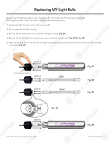
HALOGEN BULBS
This range hood requires two halogen bulbs
(Type T3, 12Volt, 20Watt Max, G-4 Base).
WARNING: Always switch off the elec-
trical supply before carrying out any op-
eration on the appliance.
To change bulbs:
1. Open the cover by prying from the proper
slots. Fig. 2.
2. Remove the bulb by pulling sideways.
(DO NOT ROTATE).
!
CAUTION: Bulb may be hot.
3. Replace with Type T3, 12Volt, 20 Watt Max, G-4 Base halogen bulb. Do not touch
replacement bulb with bare hands!
!
CAUTION: Use of bulbs greater than 20 watts will cause the fuse to open.
OPERATION
Controls
The hood is operated using the (4) push-but-
tons located at eye-level, on the front edge of
the hood.
The light switch turns the halogen lights on
and off.
The blower on-low / off switch turns the blower
on to its lowest running speed. The blower
must be turned on using this switch. Turn the
blower off by pressing this switch a second time.
The blower medium speed switch changes the blower speed to medium. This
switch works only if the blower is already running at low or high speed.
The blower high speed switch changes the blower speed to high. This switch works
only if the blower is already running at low or medium speed.
The pilot lamp lights up whenever the blower is on.
HEAT SENTRY™
Your hood is equipped with a HEAT SENTRY™ thermostat. This thermostat is a
device that will turn on or speed up the blower if it senses excessive heat above
the cooking surface.
1) If blower is OFF - it turns blower ON to HIGH speed.
2) If blower is ON at a lower speed setting - it turns blower up to HIGH speed.
When the temperature level drops to normal, the blower will return to its original
setting.
WARNING
The HEAT SENTRY thermostat can start the blower even if the hood is turned
OFF. When this occurs, it is impossible to turn the blower OFF with its switch.
If you must stop the blower, do it from the main electrical panel.
BLOWER
ON-LOW /
OFF
SWITCH
BLOWER
MEDIUM
SPEED
LIGHT
SWITCH
PILOT
LAMP
BLOWER
HIGH
SPEED
FIG. 1
FIG. 2

- 5 -
FUSE REPLACEMENT
IF LIGHTS FAIL TO OPERATE,
DISCONNECT THE POWER AT THE
SERVICE ENTRANCE. CHECK THE FUSE
AND REPLACE IF NECESSARY.
1. Remove the decorative flue.
2. Remove the cover from the fuse box.
3. Locate the fuse holder. Unscrew its cap
and remove the fuse.
4. Replace the fuse with the same size and
amperage (5x20mm, 4amp, 125volt).
!
CAUTION: Use of a fuse greater than
4 amps may damage the transformer.
5. Reinstall the fuse holder cap, the fuse
box cover and decorative flues.
6. Reconnect power at the service
entrance.
FUSE
FUSE BOX
DECORATIVE FLUE
FIG. 3

- 6 -
MAINTENANCE
Proper maintenance of the Range Hood will assure proper performance of the unit.
Grease Filter
The grease filter should be cleaned frequently. Use a warm detergent solution.
Grease filter is dishwasher safe.
See “INSTALL FILTERS” section for removal and installation instructions.
Non-ducted Recirculation Filter
The non-ducted recirculation filter should be changed every 6 months. See “INSTALL
FILTERS” section for removal and installation instructions.
Hood Cleaning
Stainless steel is one of the easiest materials to keep clean. Occasional care will
help preserve its fine appearance.
Cleaning tips:
O Hot water with soap or detergent is all that is usually needed.
O Follow all cleaning by rinsing with clear water. Wipe dry with a clean, soft cloth to
avoid water marks.
O For discolorations or deposits that persist, use a non-scratching household cleanser
or stainless steel polishing powder with a little water and a soft cloth.
O For stubborn cases, use a plastic scouring pad or soft bristle brush together with
cleanser and water. Rub lightly in direction of polishing lines or "grain" of the
stainless finish. Avoid using too much pressure which may mar the surface.
O DO NOT allow deposits to remain for long periods of time.
O DO NOT use ordinary steel wool or steel brushes. Small bits of steel may adhere
to the surface causing rust.
O DO NOT allow salt solutions, disinfectants, bleaches, or cleaning compounds to
remain in contact with stainless steel for extended periods. Many of these com-
pounds contain chemicals which may be harmful. Rinse with water after expo-
sure and wipe dry with a clean cloth.
Painted surfaces should be cleaned with warm water and mild detergent only.

- 7 -
PREPARE THE HOOD
Unpack hood and check contents.
You should receive:
1 - Hood
1 - Decorative Flue Assembly
1 - Parts Bag (B080810501) containing:
1 - Mounting Bracket
1 - Discharge Collar
1 - Flue Mounting Bracket
8 - Mounting Screws (4.8 x 38mm Pan Head)
6 - Mounting Screws (3.9 x 9.5mm Pan Head)
2 - Bracket Screws (3.9 x 6mm Flat Head)
8 - Drywall Anchors
1 - Installation Instructions
MOUNTING
BRACKET
DISCHARGE
COLLAR
FLUE MOUNTING
BRACKET
8 MOUNTING SCREWS
(4.8 x 38mm Pan Head)
8 DRYWALL
ANCHORS
6 MOUNTING SCREWS
(3.9 x 9.5mm Pan Head)
DECORATIVE
FLUE
2 BRACKET SCREWS
(3.9 x 6mm Flat Head)
FIG. 4

- 8 -
ROOF CAP
ROUND DUCT
DECORATIVE
FLUE
HOOD
WALL
CAP
ROUND
ELBOW
24” TO 30” ABOVE
COOKING SURFACE
(see “INSTALL
MOUNTING
BRACKETS” section for
mounting restrictions)
INSTALL THE DUCTWORK
DUCTED HOODS ONLY
NOTE: To reduce the risk of fire, use only
metal ductwork.
1. Decide where the ductwork will run
between the hood and the outside.
2. A straight, short duct run will allow the hood
to perform most efficiently.
3. Long duct runs, elbows, and transitions
will reduce the performance of the hood.
Use as few of them as possible. Larger
ducting may be required for best
performance with longer duct runs.
4. Install a roof or wall cap. Connect round
metal ductwork to cap and work back to-
wards hood location. Use duct tape to seal
the joints between ductwork sections.
6”
ADAPTER
FIG. 5
INSTALL ELECTRICAL
DUCTED and NON-DUCTED HOODS
WARNING : Electrical wiring must be
done by a qualified person(s) in
accordance with all applicable codes and
standards. This range hood must be
properly grounded. Turn off electrical
power at service entrance before wiring.
GROUNDING INSTRUCTIONS
This appliance must be grounded. In the
event of an electrical short circuit, grounding
reduces the risk of electric shock by
providing an escape wire for the electric
current. This appliance is equipped with a
cord having a grounding wire with a grounding plug. The plug must be plugged
into an outlet that is properly installed and grounded.
WARNING - Improper grounding can result in a risk of electric shock.
Consult a qualified electrician if the grounding instructions are not completely
understood, or if doubt exists as to whether the appliance is properly grounded.
Do not use an extension cord. If the power supply cord is too short, have a qualified
electrician install an outlet near the appliance.
1. Plan where the hood will be located above the cook top. Refer to the “INSTALL
MOUNTING BRACKET” section for hood mounting height options.
2. Run 2-wire plus ground power cable to a standard 2” x 4” wall outlet box and 3-
blade, 125 volt, 15 Amp grounded receptacle. Fig. 6.
3. Mount the receptacle 17” to 19” above the bottom of the hood.
4. Locate the box and the receptacle within boundary shown and off center of the
ductwork (to allow for power cord plug and flue clearance).
FIG. 6
17”-19”
4”
8”

- 9 -
INSTALL MOUNTING
BRACKET
DUCTED and NON-DUCTED HOODS
1. Construct wood wall framing that is flush
with interior surface of wall studs. Fig. 7.
Make sure:
a) the framing is centered over
installation location.
b) the height of the framing will allow the
mounting bracket to be secured to
the framing within the dimensions
shown.
2. After wall surface is finished, secure the
mounting bracket to framing with (2) 4.8 x
38mm mounting screws. See chart below
for mounting bracket location.
Notes:
a. Minimum hood distance above cook top must not be less than 24”.
A maximun of 30” above cook top is highly recommended for best capture of
cooking impurities.
Distances over 30” above the cook top are at the installer’s and user’s discretion;
providing that ceiling height and flue length permit.
b. Requires optional 10 foot flue extension, ducted model FX55SS or non-ducted
model FXN55SS.
HOOD DISTANCE ABOVE 36” HIGH COOK TOP (see note a)
30”
MOUNTING BRACKET LOCATION ABOVE 36” HIGH COOK TOP
43-1/8”
CEILING HEIGHT
8-FOOT
9-FOOT
24” 25” 26” 27” 28” 29”
37-1/8” 38-1/8” 39-1/8” 40-1/8”
10- FOOT (see note b)
41-1/8” 42-1/8”
40-1/8”
38-1/8” 39-1/8” 40-1/8”
43-1/8”41-1/8” 42-1/8”
FRAMING BEHIND
WOOD CROSS
SUPPORT
WOOD CROSS
SUPPORT BEHIND
DRYWALL
DRYWALL
FIG. 7
41-1/8” 42-1/8” 43-1/8”

- 10 -
INSTALL FLUE MOUNTING
BRACKET
DUCTED AND NON-DUCTED HOODS
1. Assemble the flue mounting bracket,
adjusting outside width as shown. Fig.8
2. Carefully center the mounting bracket
directly over the range hood location.
3. Secure the bracket assembly to the ceiling
using (2) 4.8x38mm mounting screws
and drywall anchors (Fig. 9). Make sure
the bracket is pushed into the corner,
tight against the wall and centered over
the hood.
FLUE MOUNTING BRACKET
10-5/8”
(270 mm)
FIG. 8
3.9 x 6 mm FLAT HEAD
BRACKET SCREWS
FIG. 9
4.8x38mm
MOUNTING SCREWS
DRYWALL ANCHORS
DISCHARGE
COLLAR
PREPARE THE HOOD
Note: On stainless steel hoods, carefully remove the plastic protective film
from all exterior surfaces of the hood and decorative flues, prior to final
installation.
DUCTED CONFIGURATION
1. Remove the tape on the electrical system plate; place the electrical system plate
on the hood (use a protection). Fig. 10
2. Install the discharge collar into the duct connector of the range hood. Fig. 11
DUCT
CONNECTOR
FIG.10
ELECTRICAL SYSTEM
PLATE
PROTECTION
FIG.11

- 11 -
PREPARE THE HOOD
NON - DUCTED HOODS ONLY
Note: The following materials must be purchased separately for non-ducted
recirculation installations.
• Non - Ducted Recirculation Kit, Model RK55.
• 5” diameter duct.
1. Remove the tape on the electrical system plate; place the electrical system plate
on the hood (use a protection). Fig.12.
2. Discard discharge collar/damper supplied with the hood. Install the 5” to 6”
adapter supplied with the Non-Ducted Recirculation Kit.
3. Secure the plenum to the flue mounting bracket with (2) 3.9x6mm flat head
screws (the screws are supplied with the Non-Ducted Recirculation Kit). Fig.13.
3.9x6mm
FLAT HEAD
SCREWS
PLENUM
FLUE MOUNTING
BRACKET
FIG.13FIG.12
ELECTRICAL
SYSTEM
PLATE
PROTECTION
5”-6”
ADAPTER

- 12 -
FIG.14
MOUNTING SCREWS
(4.8x38mm)
RECTANGULAR
CUTOUT
WALL FRAMING
MOUNTING
BRACKET
MOUNTING
SCREWS
(3.9x9.5mm)
FIG.15
ELECTRICAL
SYSTEM
PLATE
MOUNTING
SCREWS
(3.9x9.5mm)
INSTALL THE
HOOD
DUCTED AND NON-
DUCTED HOODS
Note: at least two people
will be required to mount the
hood.
1. Raise the hood into its
mounting position.
2. Align the rectangular
opening on the back of
the hood with the wall-
mounting bracket. Gently
lower the hood until it
securely engages the
bracket. Fig. 14.
3. Level the hood with (2) 3.9x9.5mm
mounting screws and secure with (4)
4.8x38mm mounting screws. Use drywall
anchors provided if wall studs or framing
are not available. Fig. 14.
4. Mount the electrical system plate attaching
it with (3) 3.9x9.5 mounting screws. Fig.15.
5. On ducted hoods, attach 6” round metal
duct between the hood’s blower collar
and duct that leads to the outside location.
6. On non-ducted hoods, attach 5” round
metal expandable duct between the 5”-6”
adapter on the hood and the connector on
the plenum.
7. Tape all duct joints to make them secure
and air tight.
8. Plug the power cord into the electric wall
receptacle. Tuck excess cord behind the
flue.

- 13 -
UPPER
FLUE
LOWER
FLUE
FIG.16
UPPER FLUE VENTS
CONCEALED
UPPER
FLUE
LOWER
FLUE
UPPER FLUE VENTS
EXPOSED
INSTALL THE HOOD, cont’d
9. Carefully place the decorative flue on the hood. Fig. 16.
- On ducted installation in rooms with 8-foot ceilings, the air vents are
concealed. Install the flue with the air vents down.
- On non-ducted installations in rooms with 8-foot ceilings, the air vents are
exposed. Install the flue with the air vents up.
- On ducted and non-ducted installations in rooms with 9-foot ceilings, the
vents are exposed. Install the flue with air vents up.
ROOMS WITH 10-FOOT CEILINGS
Rooms with 10-foot ceilings require flue extension model FX55SS or non-ducted
model FXN55SS, available from your local dealer.
10. Discard the upper flue supplied with the product. Replace it with the flue
extension.
11. Raise the upper flue until its holes align with holes in the flue mounting bracket
(located on ceiling). Fig. 17.
12. Secure the flue with (2) 3.9x9.5mm mounting screws. Fig. 17.
3.9x9.5mm
MOUNTING SCREWS
FIG.17

- 14 -
BROAN-NUTONE LLC ONE YEAR LIMITED WARRANTY
Broan-NuTone LLC warrants to the original consumer purchaser of its products that such products will be free from defects
in materials or workmanship for a period of one year from the date of original purchase. THERE ARE NO OTHER WAR-
RANTIES, EXPRESS OR IMPLIED, INCLUDING, BUT NOT LIMITED TO, IMPLIED WARRANTIES OR MERCHANT
ABILITY OR FITNESS FOR A PARTICULAR PURPOSE.
During this one-year period, Broan-NuTone LLC will, at its option, repair or replace, without charge, any product or part which
is found to be defective under normal use and service.
THIS WARRANTY DOES NOT EXTEND TO FLUORESCENT LAMP STARTERS, TUBES, HALOGEN AND
INCANDESCENDT BULBS. This warranty does not cover (a) normal maintenance and service or (b) any products or parts
which have been subject to misuse, negligence, accident, improper maintenance or repair (other than by Broan-NuTone LLC),
faulty installation or installation contrary to recommended installation instructions.
The duration of any implied warranty is limited to the one-year period as specified for the express warranty. Some states do
not allow limitation on how long an implied warranty lasts, so the above limitation may not apply to you.
BROAN-NUTONE LLC’S OBLIGATION TO REPAIR OR REPLACE, AT BROAN-NUTONE LLC’S OPTION, SHALL BE
THE PURCHASER’S SOLE AND EXCLUSIVE REMEDY UNDER THIS WARRANTY. BROAN-NUTONE LLC SHALL
NOT BE LIABLE FOR INCIDENTAL, CONSEQUENTIAL OR SPECIAL DAMAGES ARISING OUT OF OR IN CONNEC-
TION WITH PRODUCT USE OR PERFORMANCE. Some states do not allow the exclusion or limitation of incidental or
consequential damages, so the above limitation or exclusion may not apply to you.
This warranty gives you specific legal rights, and you may also have other rights, which vary from state to state. This warranty
supersedes all prior warranties.
To qualify for warranty service, you must (a) notify Broan-NuTone LLC at the address stated below or telephone: 1-800-637-
1453, (b) give the model number and part identification and (c) describe the nature of any defect in the product or part. At the
time of requesting warranty service, you must present evidence of the original purchase date.
Broan-NuTone LLC. 926 West State Street, Hartford, WI 53027 (1-800-637-1453)
NuTone Inc., 4820 Red Bank Road, Cincinnati, OH 45227 (1-800-543-8687)
Broan-NuTone Canada Inc. 1140 Tristar Drive, Mississauga, Ontario L5T 1H9 (1-888-882-7626)
WARRANTY
INSTALL FILTERS
(DUCTED AND NON-DUCTED HOODS)
1. To remove the GREASE filter, push in on
the metal latch tab and tilt filter downward
to remove.
2. To install the GREASE filter, align rear
filter tabs with slots in the hood. Depress
the metal latch tab, push filter into posi-
tion and release. Make sure filter is se-
curely engaged after installation.
NOTE: Prior to use, remove protective film
from the filter frame.
(NON-DUCTED HOODS ONLY)
1. To remove the CHARCOAL filter, push in
on the front filter latch. Pull the filter down
to disengage the rear filter tabs.
2. To install the CHARCOAL filter, align the
rear filter tabs with slots in the hood. Push
the filter up into place until the front latch
snaps securely into the slot. Make sure
the filter is securely engaged after as-
sembly.
3. Install GREASE filter after charcoal filter
is installed.
CLAMP
GREASE
FILTERS
NON-DUCTED
RECIRCULATION
FILTER

- 41 -
SERVICE PARTS
MODEL E55000
KEY NO. PART NO. DESCRIPTION
7 BE3346761 Filter Support
9 B08087092 Grease Filter
14 B02300233 Motor Capacitor
16 BE3346354 Electrical Box Support
19 B03295005 Transformer Protection
26 B02300891 Halogen Lamp Bulb
37 B02300804 Heat Sentry
45 BW0000019 Blower
48 B02310203 Motor
49 B03295076 Blower Wheel
53 B03204177 Rubber Washer
60 B02300249 Feeder Cable
62 B08091462 Blower Mounting Cover
76 B02005121 Glass
86 B08088378 Discharge Collar
92 BE3348916 Switch Mounting Bracket
113 B02011314 Nameplate
118 BE3348941 Decorative Flue Bottom
119 BE3346765 Decorative FlueTop
120 B08091367 Flue Mounting Bracket
145 B032920170 Feeder cable connection Box
146 B032920180 Feeder Cable Connection Box Cover
147 BR2300132 Junction Clamp
151 B032920200 Electrical Box Wires Stop
165 B03295008 Control Board Box
166 B08086668 Control Board
208 B02300783 Transformer
223 B03200351 Switch Button
228 B08086286 Controls Board
229 B03201014 Warning lamp
230 B03292303 Switch Board Box Cover
234 B03292302 Control Board Box
240 B03292301 Switch Support
252 B03294836 Limit Switch Box
253 B02300620 Limit Switch
254 B03294837 Limit Switch Box Cover
274 B03295035 Fuse Box
332 B03295009 Cover
367 B02011210 Glass Handle
407 BE3344985 Blower Support Bracket
474 B02300798 Halogen Lamp Housing
477 B03295006 Transformer Protection Cover
998 B080810501 Hardware Package
SGD B08091764 Glass Slide
* B06002013 Blower Assembly (Includes Key Nos. 45, 48,
49, 53)
* B06108719 Switch Assembly (Includes Key Nos. 253,
14, 165, 228, 230, 234, 252, 254)
- B03300488 Non-ducted recirculation filter
- B08999660 Non-ducted recirculation KIT
- B02300782 Fuse
- B02300674 Fuse holder
* Not shown assembled.

SERVICE PARTS - LISTE PIECES DE RECHANGE -
LISTA DE PIEZAS DE RECAMBIO
MODEL E55000
04307635/3S
/