4 En
The Yamaha Parametric room Acoustic Optimizer (YPAO) function detects speaker connections, measures the
distances from them to your listening position(s), and then automatically optimizes the speaker settings, such as
volume balance and acoustic parameters, to suit your room.
Preparing for YPAO
4
Optimizing the speaker settings automatically (YPAO)
SOURCE
RECEIVER
AV
AUDIO
1 2 3 4
5 6 7
V-A UX
1 2 3 4
MULTI
PHONO
USB NET
TUNER
[ C ][ A ] [ B ]
CLASSICAL
LIVE
CLUB
ENTERTAIN
MOVIE
STEREO STRAIGHT
INPUT
PURE
DIRECT
MUTE
TV
SCENE
1 2 3 4
PROGRAM
VOLUME
TV VOL
MUTE
MODE
TOP MENU
RETURN DISPLAY
POP-UP/MENU
TV CH
PRESET
ENTER
ON SCREEN
OPTION
D
V
A
X
H
N
C
A
LA
I
A
L
M
TERE
TRAI
HT
DIRE
EN
OGR
LUME
V
M
D
T
DI
P
P
P-
P
MEN
TV
PRE
E
N
REE
PTI
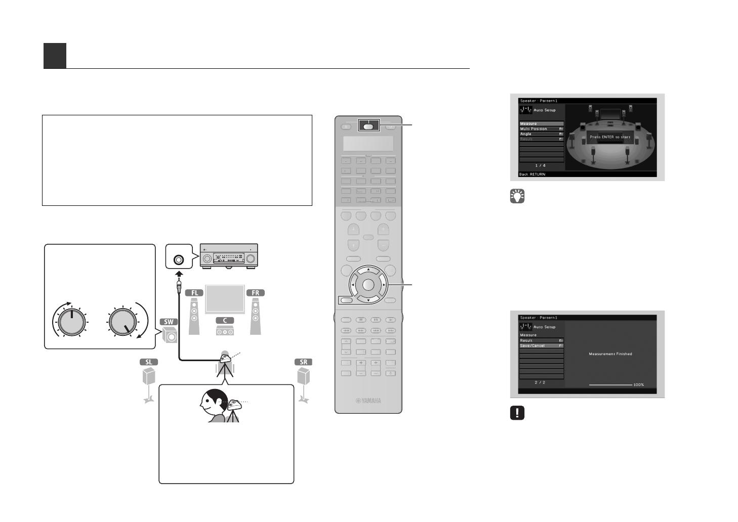
• During the measuring process, test tones are output at high volume. Ensure that the
test tones do not frighten small children. Also, refrain from using this function at night
when it may be a nuisance to others.
• During the measuring process, you cannot adjust the volume.
• During the measuring process, keep the room as quiet as possible.
• Do not connect headphones.
• Do not stand between the speakers and the YPAO microphone during the
measurement process (about 3 minutes).
• Move to the corner of the room or leave the room.
YPAO MIC
VOLUME HIGH CUT
CROSSOVER/
MIN MAXMIN MAX
The unit (front)
Place the YPAO microphone at your
listening position (same height as your
ears). We recommend the use of a
tripod as a microphone stand. You can
use the tripod screws to fix the
microphone in place. (The microphone
direction is not considered.)
YPAO
microphone
Ear height
Turn on the subwoofer and set
the volume to half. If the
cross-over frequency is
adjustable, set it to maximum.
1
Connect the YPAO microphone to the
YPAO MIC jack on the front panel.
The following screen appears on the TV.
• To cancel the operation, disconnect the YPAO microphone
before starting the measurement.
2
To start the measurement, use the cursor
keys to select “Measure” and press
ENTER.
The measurement will start in 10 seconds.
The following screen appears on the TV when
the measurement finishes.
• If the cursor keys do not work, press SOURCE/RECEIVER (to
light up the key in orange) and then use the cursor keys.
• If any error message (such as E-1) or warning message (such
as W-2) appears, see “Error messages” or “Warning
messages” in “Owner’s Manual”.
• If the warning message “W-1:Out of Phase” appears, see
“If “W-1:Out of Phase” appears” (next page).


