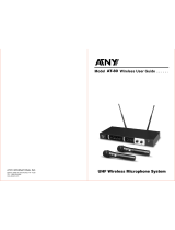
Electro-Voice REV Operating instructions

Category
Microphones
Type
Operating instructions
UHF WIRELESS
MICROPHONE SYSTEM
User Guide
Operating Instructions
-i-
Table of Contents
Section 1 - Quick Set-Up . . . . . . . . . . . . . . . . . . . . . . . . . . . . . . . . . . . . . . . . . . . . . . . . . . . . . . . . . . . . . . . . . . . . . . . 1
Section 2 - System Description . . . . . . . . . . . . . . . . . . . . . . . . . . . . . . . . . . . . . . . . . . . . . . . . . . . . . . . . . . . . . . . . . . 2
Section 3 - Detailed Component Description . . . . . . . . . . . . . . . . . . . . . . . . . . . . . . . . . . . . . . . . . . . . . . . . . . . . . . . 3
Receiver Setup and Operation . . . . . . . . . . . . . . . . . . . . . . . . . . . . . . . . . . . . . . . . . . . . . . . . . . . . . . . . . . . . . . . . .4
Headphone Operation . . . . . . . . . . . . . . . . . . . . . . . . . . . . . . . . . . . . . . . . . . . . . . . . . . . . . . . . . . . . . . . . . . . . . . .6
Antenna Connections . . . . . . . . . . . . . . . . . . . . . . . . . . . . . . . . . . . . . . . . . . . . . . . . . . . . . . . . . . . . . . . . . . . . . . . .6
Handheld Transmitter, REV-H . . . . . . . . . . . . . . . . . . . . . . . . . . . . . . . . . . . . . . . . . . . . . . . . . . . . . . . . . . . . . . . . .8
Handheld Transmitter Setup and Operation . . . . . . . . . . . . . . . . . . . . . . . . . . . . . . . . . . . . . . . . . . . . . . . . . . . . . . .9
Handheld Transmitter, REV-PH . . . . . . . . . . . . . . . . . . . . . . . . . . . . . . . . . . . . . . . . . . . . . . . . . . . . . . . . . . . . . . .10
Handheld Transmitter Setup and Operation . . . . . . . . . . . . . . . . . . . . . . . . . . . . . . . . . . . . . . . . . . . . . . . . . . . . . .11
Bodypack Transmitter, REV-BP . . . . . . . . . . . . . . . . . . . . . . . . . . . . . . . . . . . . . . . . . . . . . . . . . . . . . . . . . . . . . . .12
Bodypack Transmitter Setup and Operation . . . . . . . . . . . . . . . . . . . . . . . . . . . . . . . . . . . . . . . . . . . . . . . . . . . . . .13
Bodypack Transmitter, REV-WT . . . . . . . . . . . . . . . . . . . . . . . . . . . . . . . . . . . . . . . . . . . . . . . . . . . . . . . . . . . . . . .14
Bodypack Transmitter Setup and Operation . . . . . . . . . . . . . . . . . . . . . . . . . . . . . . . . . . . . . . . . . . . . . . . . . . . . . .15
Section 4 - Receiver Display Screens and Functions . . . . . . . . . . . . . . . . . . . . . . . . . . . . . . . . . . . . . . . . . . . . . . . 17
Main Operating Screen . . . . . . . . . . . . . . . . . . . . . . . . . . . . . . . . . . . . . . . . . . . . . . . . . . . . . . . . . . . . . . . . . . . . . .17
Group/Channel Edit Screen . . . . . . . . . . . . . . . . . . . . . . . . . . . . . . . . . . . . . . . . . . . . . . . . . . . . . . . . . . . . . . . . . .18
Functions Screen . . . . . . . . . . . . . . . . . . . . . . . . . . . . . . . . . . . . . . . . . . . . . . . . . . . . . . . . . . . . . . . . . . . . . . . . . .19
ClearScan All groups . . . . . . . . . . . . . . . . . . . . . . . . . . . . . . . . . . . . . . . . . . . . . . . . . . . . . . . . . . . . . . . . . . . .19
ClearScan Group . . . . . . . . . . . . . . . . . . . . . . . . . . . . . . . . . . . . . . . . . . . . . . . . . . . . . . . . . . . . . . . . . . . . . . .20
ClearScan Band . . . . . . . . . . . . . . . . . . . . . . . . . . . . . . . . . . . . . . . . . . . . . . . . . . . . . . . . . . . . . . . . . . . . . . . .20
Audio Edit . . . . . . . . . . . . . . . . . . . . . . . . . . . . . . . . . . . . . . . . . . . . . . . . . . . . . . . . . . . . . . . . . . . . . . . . . . . . .21
Guitar Mode . . . . . . . . . . . . . . . . . . . . . . . . . . . . . . . . . . . . . . . . . . . . . . . . . . . . . . . . . . . . . . . . . . . . . . . . . . .21
Set Squelch Threshold . . . . . . . . . . . . . . . . . . . . . . . . . . . . . . . . . . . . . . . . . . . . . . . . . . . . . . . . . . . . . . . . . . .21
Sound Check Screen . . . . . . . . . . . . . . . . . . . . . . . . . . . . . . . . . . . . . . . . . . . . . . . . . . . . . . . . . . . . . . . . . . . .22
Copy Group . . . . . . . . . . . . . . . . . . . . . . . . . . . . . . . . . . . . . . . . . . . . . . . . . . . . . . . . . . . . . . . . . . . . . . . . . . .22
Clear Group . . . . . . . . . . . . . . . . . . . . . . . . . . . . . . . . . . . . . . . . . . . . . . . . . . . . . . . . . . . . . . . . . . . . . . . . . . .23
Name Edit Screen . . . . . . . . . . . . . . . . . . . . . . . . . . . . . . . . . . . . . . . . . . . . . . . . . . . . . . . . . . . . . . . . . . . . . .23
CAN Bus Address . . . . . . . . . . . . . . . . . . . . . . . . . . . . . . . . . . . . . . . . . . . . . . . . . . . . . . . . . . . . . . . . . . . . . .24
Section 5 - Transmitter Screens and Detail Functions . . . . . . . . . . . . . . . . . . . . . . . . . . . . . . . . . . . . . . . . . . . . . . 25
Transmitter Display and Controls . . . . . . . . . . . . . . . . . . . . . . . . . . . . . . . . . . . . . . . . . . . . . . . . . . . . . . . . . . . . . .25
Lockout . . . . . . . . . . . . . . . . . . . . . . . . . . . . . . . . . . . . . . . . . . . . . . . . . . . . . . . . . . . . . . . . . . . . . . . . . . . . . . . . . .25
Transmitter On/Off Lockout . . . . . . . . . . . . . . . . . . . . . . . . . . . . . . . . . . . . . . . . . . . . . . . . . . . . . . . . . . . . . . . . . .25
Section 6 - Guidelines for Best Performance. . . . . . . . . . . . . . . . . . . . . . . . . . . . . . . . . . . . . . . . . . . . . . . . . . . . . . 26
Section 7 - Trouble Shooting Guide . . . . . . . . . . . . . . . . . . . . . . . . . . . . . . . . . . . . . . . . . . . . . . . . . . . . . . . . . . . . . 27
Section 8 - Technical Specifications . . . . . . . . . . . . . . . . . . . . . . . . . . . . . . . . . . . . . . . . . . . . . . . . . . . . . . . . . . . . . 29
Section 9 - Approval Information . . . . . . . . . . . . . . . . . . . . . . . . . . . . . . . . . . . . . . . . . . . . . . . . . . . . . . . . . . . . . . . 30
Section 10 - Factory Service . . . . . . . . . . . . . . . . . . . . . . . . . . . . . . . . . . . . . . . . . . . . . . . . . . . . . . . . . . . . . . . . . . . 31
Section 11 - Accessories and Parts . . . . . . . . . . . . . . . . . . . . . . . . . . . . . . . . . . . . . . . . . . . . . . . . . . . . . . . . . . . . . 32
ENGLISH
-1-
Quick Set-up: Receiver
1. Do not connect the receiver to any other equipment yet!
2. Connect the two Antennas to the receiver.
3. Plug the power cord into the back of the receiver and into
an outlet.
4. Press the Power switch. Display will light up, show EV
name and software revision numbers for about 3 seconds
and then display the main operating screen.
5. Press the MENU button twice to display the MENU option
screen and then press set.
6. With the CLEARSCAN ALL line highlighted, press SET.
7. ClearScan
TM
returns the clearest group. Press SET again.
8. ClearScan returns the clearest channel in that group.
Press SET again.
9. The display will return to the main operating screen with the
clearest channel in the clearest group assigned.
10. Turn the receiver off and connect the mixer or other audio
system to the receiver XLR Mic/Line Level Connector or the
1/4 inch Line Level Jack.
11. Set the audio mixer or other system input level to minimum.
12. Turn receiver back on.
Receiver “Quick Set-up” is complete.
Quick set-up: Transmitter
1. With the Power switch on the transmitter OFF, install a fresh
Battery (9V or two AA) into the transmitter.
2. Place the transmitter Power Switch to the ON position.
3. The LCD display backlight will come on and display Group
and Channel and battery level.
4. Press the SET button once and the Group number will
flash.
5. Use the up and down arrows to change the Group number
to match the channel number displayed on the receiver.
Press SET and the Channel Number will flash.
6. Use the up and down arrow buttons to change the Channel
to match the receiver. Press Set and nothing will be flash-
ing, the channel is now set.
7. If you are using a bodypack transmitter, plug the micro-
phone into the transmitter connector. If using a quitar, put
the bodypack and receiver into instrument mode (see page
5, Part K and page 13, Part G).
Transmitter “Quick Set-up” is complete.
Quick set-up: System Operation
1. With the transmitter and receiver on, monitor the REV
Receiver main display screen. Note that the RF (1-100) Bar
graph should indicate near the 100 mark. The AF Bar
should show very little if any, indication until you talk or sing
into the microphone.
2. On the transmitter, press Set and Down buttons at the
same time twice to access the gain adjustment mode.
3. Press set and use the Up and Down buttons to adjust the
transmitter gain to cause the AF Bar Graph to peak
between 50 and 100 for best performance.
4. Set the mixer/amp gain.
5. Talk or sing into the microphone or play the guitar at a nor-
mal volume. You should hear audio coming out of the sys-
tem.
6. If you are not getting enough level at the input of the mixer,
see the audio output gain adjustment section on page 5.
Section 1 - Quick Set-Up
“Quick Set-up” is now complete. Please enjoy your
REV system.
ENGLISH
-2-
System Description
The REV Wireless Microphone system combines frequency
agility and ease of use like no other. The REV transmitters
and receivers operate over a 24 MHz bandwidth in the UHF
portion of the spectrum.
System Features Include:
The high quality audio circuitry and advanced Radio
Frequency (RF) signal processing offer broadcast quality sig-
nal-to-noise and audio clarity.
Section 2 - System Description
.
Advanced ClearScan technology for selecting clear channels and inter-modulation free groups
.
960 Radio Channels, user programmable or factory installed
.
LCD Displays for ease of viewing
.
Patented DSP Phase Diversity System
.
CAN Bus Port for computer monitor, control, and updating
.
Adjustable Unbalanced Line Level 1/4 inch output jack
.
Adjustable Balanced Microphone Line Level XLR output jack
.
Front Panel Power ON/OFF Switch
.
Permanent Flash Memory for frequency/system storage
.
Front Panel Software Control of Squelch and Audio Output settings
.
Combination Squelch (Amplitude and Tone) system prevents false squelch
.
Lockout feature to prevent accidental channel changes
.
Sound Check mode to speed walk testing and provide tangible results
.
Backlit LCD displays on transmitters for easy adjustment on dark stages
.
“Smart” battery feature in the 9V transmitters means there is no wrong orientation
.
Interchangeable heads on the handheld transmitters
.
Cast magnesium case on the bodypack transmitter
.
Optimized Guitar settings on transmitter and receiver
ENGLISH
REV-S or REV-D Receiver
REV Receiver Controls, Connectors, and Indicators
1. Power ON/OFF
2. 1/4” headphone jack with adjustable volume
(channel selection on REV-D)
3. Graphical Display
a. Channel Display
b. Battery Strength Indicator
c. Diversity Indicator
d. RF Strength of Signal Indicator
e. Audio Level Indicator
4. Display Control Buttons (Menu/Set/Up/Down)
5. IEC Power Cord Connector
6. XLR Balanced Audio Output Connector (two on REV-D)
7. Unbalanced 1/4” Line Level Audio Output Connector
(two on REV-D)
8. TNC Antenna Input Connectors
9. REV-D TNC Antenna Output connectors
10. CAN Bus RJ45 connectors (two in parallel)
-3-
Section 3 - Detailed Component Descriptions
Figure 1
Front Panel
Figure 2
Back Panel
ENGLISH
3.1 Receiver Setup and Operation
A. Receiver Setup
1. Place the receiver and antennas where there is a clear
line of sight to the area where the transmitter will be used.
Rotate the antennas to separate them by 90 degrees.
See Part 15 for more information.
2. Connect the power cord to the receiver. Turn the receiv-
er on and confirm that it is ON by checking the main dis-
play screen. The display will show the company logo,
software revision level and then display the main screen
with the last channel set.
B. Manual Channel Change
1. From the main display screen press the MENU button
once to display the edit screen.
2. Press SET and the group number will flash. The UP and
DOWN buttons allow you to scroll through the 18 factory
groups and 2 user definable groups.
3. When the group you desire is displayed, press SET to select
that group and the Channel Number will start flashing.
4. Scroll to the desired channel, press SET to select.
5. Pressing MENU anytime before pressing SET negates
any changes made since the last SET.
6. Once the desired group and channel are displayed (but
not flashing) press MENU twice to return to the main dis-
play screen.
C. Frequency Assignment (User Defined Groups Only)
1. With a User Group (19u or 20u) and channel selected in
step three, press SET until the Frequency Number flashes.
2. Use UP/DOWN to scroll in 25 kHz steps to the desired
frequency. With the desired frequency displayed press
SET. Hint: holding in the arrow key will increase the
speed of the scroll. Just release and press again for fine
control.
3. Repeat until all desired Channels in the user group are
assigned a frequency.
4. Press MENU twice to return to the main display screen.
D. Advanced ClearScan: This feature automates the process
of finding a clear group of inter-modulation free channels
and the clearest channels within those groups. From the
main display screen push Menu twice to go to the MENU
Screen and press SET to select ClearScan.
E. ClearScan All: This function scans all of the groups (factory
and user) and returns a list of groups ranked by the number
of free channels.
1. Once ClearScan All has run, the screen will display the
clearest group with the open channels in that group. You
can scroll through the other ranked groups using
UP/DOWN.
2. When you have the group you want, press SET to run
ClearScan on that group. The display will now show the
group with the Channels ranked by clearness and the
clearest channel will be flashing.
3. Press SET to select and the clearest channel will be
installed, display will return to the main display.
NOTE: Groups 17 and 18 have 16 channels and are marked with
an N (17n). These groups require the transmitters to be in
the LOW transmit power setting to work together. After
ClearScan All runs, the N groups will always be displayed
after groups 1-18 and any user defined groups no matter
how many channels are free. If you need to use more than
12 systems at one time, scroll down to the N groups and
use the clearest group with Normal transmit power.
F. ClearScan Group: this function will scan the group currently
selected, which is useful for multi-system setup.
1. Use ClearScan All on the first unit of a multi-system instal-
lation to select the clearest group.
2. For each system added, leave all previously selected
channel transmitters on, using Step 3 select the current
group, select ClearScan Group and press SET.
3. The display will show the remaining clear channels in the
group with the clearest flashing.
4. Select the desired channel with UP/DOWN or simply press
SET for the clearest channel.
5. The channel will be selected and return to the main display.
6. Repeat until all systems are set up.
G. ClearScan Band: selects and ranks the clearest 16 frequen-
cies in the 24 MHz bandwidth regardless of groups, channels
or previous coordination. This feature is useful for selecting
one clear channel in a very busy RF environment.
1. From the Options screen, select ClearScan Band and
press SET.
2. This scan will run until SET is pressed again so it can be
used to evaluate a site over an hour, day or even a week.
3. To end scan, press SET, the program displays Group 21S
with the clearest open frequencies in the band assigned
channels (up to 16).
4. These frequencies will remain assigned to this group until
ClearScan Band is run again.
Caution: Unlike the factory assigned groups, the channels in
21S are not coordinated. If more than two channels from group
21S are used, the combination must be walk tested with all
transmitters on before use.
-4-
ENGLISH
-5-
H. Change Lock-Out: Protects settings by disabling the SET
button.
1. To engage lock-out press and hold the UP and DOWN
arrow keys together for 5 seconds, until the padlock sym-
bol appears.
2. The MENU button still allows different screens to be dis-
played but no settings can be changed and ClearScan
will not run.
3. To reactivate the SET key, press and hold the UP and
DOWN keys again for 5 seconds until the padlock sym-
bol disappears.
I. Continue Set Up: make certain the mixer or amplifier input
used for the REV is muted or turned down to a minimum level.
J. Plug an audio cable (not supplied) into the 3 pin XLR or 1/4
inch output of the receiver.
NOTE: The XLR connector is the preferred connection since the
output is balanced and will be more immune to noise for
longer runs of cable, although either can be used with good
results.
K. Voice or Guitar: The REV system guitar optimization mode
requires both the transmitter and receiver be placed into gui-
tar mode.
1. Press Menu twice to display the options screen, scroll
down to Audio Edit and press SET.
2. With the Audio Edit Screen displayed press SET until
Audio setting flashes.
3. Use UP/DOWN to select Voice or Guitar mode. The
default setting is Voice.
4. Make certain the bodypack transmitter is in the same
mode.
5. Now refer ahead to transmitter setup and return to step
10 when that is completed.
6. With the transmitter on, speak into the microphone or
play the guitar. Turn up the level on the mixer or
amplifier until you are able to hear the desired signal.
If no audio is present, repeat setup and refer to the
troubleshooting section.
L. Audio Output Level Adjustment: It may be necessary to
adjust the receiver output until the volume level from the
wireless system approximates the level of an equivalent
wired mic/instrument.
1. From the main display screen, press MENU twice to dis-
play the menu screen, scroll down to Audio Edit and
press SET.
2. Press SET to step through Mic/Line, Balanced (XLR Lvl)
and Unbalanced Audio (HiZ Lvl).
3. Use the UP and DOWN to adjust output levels when
flashing. The default settings are Mic and -18dB on the
outputs.
4 Press SET a final time so nothing is flashing to save the
setting.
5. Press MENU to return to main screen.
M. Sound Check Screen: can be used to walk test the per-
formance area.
1. From the main display screen, press MENU twice to dis-
play the options screen, scroll down to Sound Check and
press set. The sound check screen will be displayed and
it includes the following elements.
2. Peak Hold Audio Meter - allows you to set the transmit-
ter gain as high as possible for the application which
maximizes the signal to noise ratio. Sing, yell or play the
guitar at the loudest desired volume and adjust the gain
so the meter peaks between 50 and 100.
3. Low Hold RF Meter will tell you if you have adequate
coverage in the performance area. If the RF level drops
below 10 on the meter during a walk of the desired area,
reposition the antennas, or change the channel and
retest.
4. Drop Counter - will tell you if you are exceeding the
range or may have some interference problems to con-
tend with. Ideally this count would be zero for the desired
performance area. If there are several squelch breaks
while walking the area, adjust and check the antennas
and re-walk.
5. Dropout Tone - Press the UP button and the speaker
symbol will change. Now when the receiver increments
the dropout counter, it will also send a 1 kHz audio tone
out the output so you can hear where on the stage the
drop occurs. Press DOWN to turn off the tone. The tone
will also deactivate when you return to the main display.
6. Left and Right Antenna Check - Press and hold the
SET button until the screen changes to two large meters
marked L and R. This screen is used to check the conti-
nuity of the left and right antennas. If the RF levels are
not approximately the same, check connections. Press
SET to return to Sound Check Screen.
N. Squelch Adjustment - The squelch setting can be used to
maximize range or immunity to noise.
1. Turn the transmitter off and from the receiver Options
screen select Squelch and press SET.
2. The current squelch setting will be displayed, the setting
will flash and (the tone coded portion of the squelch is
turned off in set mode to allow you to notice any changes
in the amplitude squelch setting).
3. Adjust the squelch using the UP/DOWN keys and walk
test the unit. Maximum squelch (15) maximizes noise
immunity but limits the range. Minimum squelch (1) will
maximize the range but may allow noise at the end of
range.
4. Repeat until desired range coverage is acceptable with
the maximum possible squelch.
ENGLISH
Headphone Operation
1. With the transmitters and receivers setup and operating,
plug stereo headphones into the 1/4 inch jack on the front
panel.
2. The Selected Receiver LED will indicate receiver 1 is being
monitored. Press the Receiver Select button once to
change from Receiver 1 to 2.
3. Press the Receiver Select button once more and both indi-
cator LEDs will light. You can now listen to both receivers.
NOTE: if both receivers are set to the same channel, the
volume will double.
4. Pressing the Select button once more cycles back to
Receiver 1.
Antenna Connections
1. Install the two 1/2 wave antennas to the “antenna in” jacks
on the rear panel.
NOTE: The two 1/2 wave antennas included with the REV can
be remote mounted. For an additional 5dB gain use the LPA500
log periodic directional antenna.
2. The REV-DUAL is equipped with a left and right antenna
output jack. These jacks can be used to connect up to 3
REV-DUAL (6 receivers) to two antennas without any addi-
tional equipment. DO NOT remove “dummy” loads unless
connecting to another receiver.
3. Figure 3 shows the connection diagram for 3 REV-DUAL
units.
4. UP to 12 REV-DUAL units can be operated with just two
antennas with the optional APD4+ antenna distribution unit
(see Figure 4).
Figure 3
Antenna Chaining
Figure 4
Antenna Chain with APD4-B
-6-
ENGLISH
12 Volt Power On “Antenna In” Jacks
To power in line antenna amplifiers, 12 volt power is available on
the center pin of the antenna in jacks. This power is disabled
when the REV leaves the factory but may be turned on by the
installer.
To turn on the 12 volts, first take off the cover of the radio by
removing 14 screws. There is a 2 pin “header” and a “jumper”
behind the “XLR” audio connector on each of the two large print-
ed circuit boards. See Figure 5. The jumper is installed on one
pin of the header at the factory. To turn on power, unplug the
jumper and install it on both pins of the header.
CAUTION: Do not attach antennas and splitters with a DC short
circuit to the antenna in jacks when the power is turned on.
Damage could result to the splitter or receiver.
The following antennas and accessories may be used with
power on:
FA-1, CLA-X, APD4+, APD4-1+, UAA-50
The following antennas and accessories may be used with the
power off:
FA-1, CLA-X, LPA-500, APD4, APD4-1
REV-LINK PC Software
1. Software to monitor and control the REV receivers from a
PC through the USB port and a UCC-1 is available at
www.electrovoice.com. Minimum system requirements
are:
Windows 2000
512 Mbytes of RAM
One USB port
UCC-1 or N8000
CD-ROM Drive
2 Mbytes of hard drive memory
-7-
Figure 5
Moving Jumper
(Be sure to move Jumper on Both
Receiver printed circuit boards.)
Power Enabled Power Disabled
ENGLISH
3.2 Handheld Transmitter REV-HXX
REV-HXX Controls, Connectors, and Indicators
1. Main Display - LCD (Channel, Frequency and Battery Level
Gauge) Display backlight - flashes when battery is low
2. Power On/Off Switch
3. Control buttons - SET, UP, and DOWN
4. Two AA Batteries
5. Battery Cover - Screw Type
6. Interchangeable Microphone Element
-8-
Figure 6
Handheld Transmitter
Figure 7
View of Transmitter Controls
ENGLISH
-9-
Handheld Transmitter REV-HXX
A. Insert Batteries. Lower the battery cover by unscrewing it
completely. Slide down the inner cover and insert two AA bat-
teries, positive ends toward the display.
B. Turning the transmitter On - With battery compartment still
open, hold the unit so you can see the display and the con-
trol panel. Turn the unit on by sliding the power switch for-
ward to the ON position. The display backlight will light for a
second and the display will show the battery level, Group
and Channel numbers.
C. Change the group and channel numbers
1. Press SET, the Group number will flash and can be
changed with the UP/DOWN keys.
2. Once the desired Group number is showing, press SET
to select and the Channel number will flash.
3. Select the Channel and press SET again, the flashing will
stop and the channel is now set.
D. To See Other Screens
1. Press SET and DOWN at the same time to display the
exact transmit frequency.
2. Press SET and DOWN at the same time to display the
battery level in percent.
3. Press SET and DOWN again to display the gain setting
screen.
4. Press SET and DOWN again to show the RF Transmit
Level.
5. SET and DOWN one more time returns you to the Group
and Channel screen.
E. Frequency Edit Mode - (User Group Only)
1. With the frequency screen displayed, press SET and use
UP and DOWN to adjust frequency.
2. Press SET and DOWN at the same time four times to
return to Group and Channel mode.
F. Gain Setting Mode
1. With the Gain Screen displayed, press SET and the level
numbers will flash.
2. Use UP and DOWN to adjust the transmitter gain. Watch
the Audio meter on the receiver and set the gain to peak
between 50 and 100 when singing/speaking into the
microphone as loud as it will be used during the perform-
ance.
3. Press SET and DOWN at the same time two times to
return to Group and Channel mode.
NOTE: Operating with the transmitter audio gain set as high as
possible (without distortion or peaks all the way to the right end
of the meter) will result in the best performance and highest sig-
nal to noise ratio.
G. RF Transmit Level
1. With the RF Transmit Level displayed, press SET and the
Level (on the right) will flash.
2. Use UP and DOWN to set it at Hi (50mW) or Lo (5mW).
3. Press SET and DOWN at the same time once to return to
the Group and Channel mode.
H. Power Lock Out - Disables the power switch
1. To engage power lock press and hold SET, UP and
DOWN at the same time until ON-LOCK appears in the
display.
2. To turn the unit off while in ON-LOCK, place the power
switch in the OFF position and push any one of the SET,
UP or DOWN buttons.
3. To remove the lock, press and hold SET, UP and DOWN
again at the same time until ON-OFF appears in the dis-
play.
4. The ON-LOCK mode can also be entered by quickly
cycling the power switch three times. But using this
method the unit will not be in ON-LOCK the next time it is
powered up.
I. Change Lock-Out - Disables the SET button to
protect settings.
1. To engage Change Lock press and hold the UP and
DOWN arrow keys together until SECURE appears in the
display.
2. To remove the Change Lock, press and hold the UP and
DOWN keys until ACCESS appears in the display.
J. Verify reception.
1. With the transmitter and receiver on and matching Group
and Channel, the main receiver display should be indicat-
ing an RF signal on the bar graph.
2. Speak into the microphone and the Audio Meter bar
graph should indicate audio signal presence.
3. If the level meters do not show reception, make certain
the group and channel are matching and refer to the trou-
ble shooting section.
4. Go back to Section 3.1 - Receiver Setup and Operation,
Step 1, to complete system set up and test.
ENGLISH
3.3 Handheld Transmitter REV-PHXX
REV-PHXX Controls, Connectors, and Indicators
1. Main Display - LCD (Channel, Frequency and Battery
Level Gauge)
2. Red Low battery LED indicator
3. Power On/Off Switch
4. SET control button
5. Channel/Frequency Up Switch
6. Channel/Frequency Down Switch
7. Interchangeable Microphone Element
8. 9V Battery Compartment
9. Battery Cover - Screw type
-10-
Figure 8
Handheld Transmitter
Figure 9
View of Transmitter Controls
ENGLISH
Handheld Transmitter REV-PHXX
A. Insert Batteries. Remove the battery cover by unscrewing it
completely. Insert a 9V battery terminal end first into the bat-
tery compartment. NOTE: The HTU-2 unique design allows
the battery to be inserted and used reqardless of the positive
and negative terminal position.
B. Turning the transmitter On - With battery compartment still
open, hold the unit so you can see the display and the con-
trol panel. Turn the unit on by sliding the power switch for-
ward to the ON position. The low battery LED will light for a
second and the display will show the Group and Channel
numbers.
C. Change the group and channel numbers
1. Press SET, the Group number will flash and can be
changed with the UP/DOWN keys.
2. Once the desired Group number is showing, press SET
to select and the Channel number will flash.
3. Select the Channel and press SET again, the flashing will
stop and the channel is now set.
D. To see Other Screens
1. Press SET and DOWN at the same time to display the
exact transmit frequency.
2. Press SET and DOWN at the same time to display the
battery level in percent.
3. Press SET and DOWN again to display the gain setting
screen.
4. Press SET and DOWN again to show the RF Transmit
Level.
5. SET and DOWN one more time returns you to the Group
and Channel screen.
E. Frequency Edit Mode - (User Group Only)
1. With the frequency screen displayed, press SET and use
UP and DOWN to adjust frequency.
2. Press SET and DOWN at the same time four times to
return to Group and Channel mode.
F. Gain Setting Mode
1. With the Gain Screen displayed, press SET and the level
numbers will flash.
2. Use UP and DOWN to adjust the transmitter gain. Watch
the Audio meter on the receiver and set the gain to peak
between 50 and 100 when singing/speaking into the micro-
phone as loud as it will be used during the performance.
3. Press SET and DOWN at the same time two times to
return to Group and Channel mode.
NOTE: Operating with the transmitter audio gain set as high as
possible (without distortion or peaks all the way to the right end
of the meter) will result in the best performance and highest sig-
nal to noise ratio.
G. RF Transmit Level
1. With the RF Transmit Level displayed, press SET and the
level (on the right) will flash.
2. Use UP and DOWN to set it at Hi (50mW) or Lo (5mW).
3. Press SET and DOWN at the same time once to return to
the Group and Channel mode.
H. Power Lock Out - Disables the power switch
1. To engage power lock press and hold SET, UP and
DOWN at the same time until ON-LOCK appears in the
display.
2. To turn the unit off while in ON-LOCK, place the power
switch in the OFF position and push any one of the SET,
UP or DOWN buttons.
3. To remove the lock, press and hold SET, UP and DOWN
again at the same time until ON-OFF appears in the dis-
play.
4. The ON-LOCK mode can also be entered by quickly
cycling the power switch three times. But using this
method the unit will not be in ON-LOCK the next time it is
powered up.
I. Change Lock-Out- Disables the SET button to
protect settings.
1. To engage Change Lock press and hold the UP and
DOWN arrow keys together until SECURE appears in the
display.
2. To remove the Change Lock, press and hold the UP and
DOWN keys until ACCESS appears in the display.
J. Verify reception
1. With the transmitter and receiver on and matching Group
and Channel, the main receiver display should be indicat-
ing an RF signal on the bar graph.
2. Speak into the microphone and the Audio Meter bar
graph should indicate audio signal presence.
3. If the level meters do not show reception, make certain
the group and channel are matching and refer to the trou-
ble shooting section.
4. Go back to Section 3.1 - Receiver Setup & Operation
Step 10 to complete system set up and test.
-11-
ENGLISH
Rev-BP Controls, Connectors, and Indicators
1. Antenna - Flexible 1/4 wave antenna removable (replace-
ment part - see Section 10)
2. Power On/Off Switch
3. Low Battery LED Indicator
4. TA4 Audio Connector
5. LCD Display (Channel or Frequency, Battery Level Indication)
6. Display Control Buttons (SET/Up/Down)
7. Belt Clip (Removable and Detachable, Flat or Cell Phone
Style Clip)
8. 9V Battery Compartment
-12-
3.4 Bodypack Transmitter
REV-BP
Figure 10
Bodypack Transmitter
Figure 11
Control View
Figure 12
Top View
Figure 13
Belt Clip Attachment
7
OR
ENGLISH
Bodypack Transmitter REV-BP
A. Install Antenna. The REV-BP is equipped with a detachable
antenna. Screw in the antenna included with the system.
See the accessories section at the end of this manual for
optional antennas.
B. Insert Batteries. Pinch the battery door tabs inward and pull
the door open. Insert a 9V battery as indicated by +/- in the
holder. (Note: the REV-BP unique design allows the battery to
be inserted and used regardless of the positive and negative
terminal position, the indicators are there for reference only).
C. Turning the transmitter On - With battery compartment still
open, turn the unit on with Power switch on the top panel.
The battery low LED and display back light will light for a sec-
ond and the display will show the battery level, the Group
and Channel numbers.
D. Change the group and channel numbers
1. Press SET, the Group number will flash and can be
changed with the UP/DOWN keys.
2. Once the desired Group number is showing, press SET
to select and the Channel number will flash.
3. Select the Channel and press SET again, the flashing will
stop and the channel is now set.
E. To See Other Screens
1. Press SET and DOWN at the same time to display the
exact transmit frequency.
2. Press SET and DOWN at the same time to display the
battery level in percent.
3. Press SET and DOWN again to display the gain setting
screen.
4. Press SET and DOWN again to show the RF Transmit
Level.
5. Press SET and DOWN again for Voice/Guitar.
6. Set and Down one more time returns you to the Group
and Channel screen.
F. Frequency Edit Mode - (User Group Only)
1. With the frequency screen displayed, press SET and use
UP and DOWN to adjust frequency.
2. Press SET and DOWN at the same time four times to
return to Group and Channel mode.
G. Attach Microphone or Guitar/Instrument
Microphone - plug the TA4 end of the microphone cable into
the top panel of the REV-BP. Speak into the microphone and
the Audio Meter bar graph should indicate audio signal pres-
ence.
Guitar - Press SET-DOWN until voice is displayed. Press
SET, display will flash, press UP and display will change to
Guitar, press set and return to main display. NOTE: The REV
receiver must also be put into Instrument mode to optimize
the system for guitar. Plug in the guitar TA4 cable. Strum the
guitar and the Audio Meter bar graph on the receiver should
indicate audio signal presence.
H. Gain Setting Mode
1. With the Gain Setting displayed, press SET and the level
numbers will flash.
2. Use UP and DOWN to adjust the transmitter gain. Watch
the Audio meter on the receiver and set the gain to peak
between 50 and 100 when singing/speaking into the
microphone as loud as it will be used during the perform-
ance.
3. Press SET and DOWN at the same time two times to
return to Group and Channel mode.
NOTE: Operating with the transmitter audio gain set as high as
possible (without distortion or peaks all the way to the right end
of the meter) will result in the best performance and highest sig-
nal to noise ratio.
I. RF Transmit Level
1. With the RF Transmit Level displayed, press SET and the
Level (on the right) will flash.
2. Use UP and DOWN to set it at Hi (50mW) or Lo (5mW).
3. Press SET and DOWN at the same time once to return to
the Group and Channel mode.
J. Power Lock Out - Disables the power switch
1. To engage power lock press and hold SET, UP and
DOWN at the same time until ON-LOCK appears in the
display.
2. To turn the unit off while in ON-LOCK, place the power
switch in the OFF position and push any one of the SET,
UP or DOWN buttons.
3. To remove the lock, press and hold SET, UP and DOWN
again at the same time until ON-OFF appears in the display.
4. The ON-LOCK mode can also be entered by quickly
cycling the power switch three times. But using this
method the unit will not be in ON-LOCK the next time it is
powered up.
K. Change Lock-Out - Disables the SET button to
protect settings.
1. To engage Change Lock press and hold the UP and
DOWN arrow keys together until SECURE appears in the
display.
2. To remove the Change Lock, press and hold the UP and
DOWN keys until ACCESS appears in the display.
L. Verify reception
1. With the transmitter and receiver on and matching Group
and Channel, the main receiver display should be indicat-
ing an RF signal on the bar graph.
2. Speak into the microphone and the Audio Meter bar
graph should indicate audio signal presence.
3. If the level meters do not show reception, make certain
the group and channel are matching and refer to the
trouble shooting section.
4. Go back to Section 3.1 - Receiver Setup & Operation
Step 1) to complete system set up and test.
-13-
ENGLISH
-14-
ENGLISH
3.5 Bodypack Transmitter
REV-WT
Bodypack Transmitter
Control View
Top View
Belt Clip Attachment
REV-WT Controls, Connectors,and Indicators
1. Antenna - Flexible 1/4 wave antenna removable
(replacement part see Section 10)
2. Power On/Off Switch
3. Low Battery LED Indicator
4. TA4 Audio Connector
5. LCD Display (Channel or Frequency, Battery Level
Indication)
6. Display Control Buttons (Menu/Set/Up/Down)
7. Belt Clip (Removable and Detachable, Flat or Cell Phone
Style Clip)
8. Battery Compartment - Two AA
9. Battery Recharge contacts (for use optional BH-200
charging Station)
-15-
Bodypack Transmitter REV-WT
A. Install antenna. The REV-WT is equipped with a detachable
antenna. Screw in the antenna included with the system. See
the accessories section at the end of this manual for option-
al antennas.
B. Insert Batteries. Pinch the battery door tabs inward and pull
the door open. Insert two AA batteries as indicated by +/- in
the holder.
C. Turning the transmitter On - With battery compartment still
open, turn the unit on with Power switch on the top panel.
The battery low LED and display back light will light for a sec-
ond and the display will show the battery level, the Group
and Channel numbers.
D. Change the group and channel numbers
1. Press SET, the Group number will flash and can be
changed with the UP/DOWN keys.
2. Once the desired Group number is showing, press SET
to select and the Channel number will flash.
3. Select the Channel and press SET again, the flashing will
stop and the channel is now set.
E. To See Other Screens
1. Press MENU to display the exact transmit frequency.
2. Press MENU again to display the gain setting screen.
3. Press MENU again to show the RF Transmit Level.
4. Press MENU again for Voice/Guitar.
5. Press MENU again for Power Switch Setting
6. MENU one more time returns you to the Group and
Channel screen.
F. Frequency Edit Mode - (User Group Only)
1. With the frequency screen displayed, press SET and use
UP and DOWN to adjust frequency.
2. Press MENU five times to return to Group and Channel
mode.
G. Attach Microphone or Guitar/Instrument Microphone-
plug the TA4 end of the microphone cable into the top panel
of the REV-WT. Speak into the microphone and the Audio
Meter bar graph on the receiver should indicate audio signal
presence.
Guitar - Press MENU until voice is displayed. Press SET, dis-
play will flash, press UP and display will change to Guitar,
press SET and return to main display. NOTE: The REV
receiver must also be put into Guitar mode to optimize the
system for guitar. Plug in the guitar TA4 cable. Strum the gui-
tar and the Audio Meter bar graph on the receiver should
indicate audio signal presence.
H. Gain Setting Mode
1. With the Gain Screen displayed, press SET and the level
numbers will flash.
2. Use UP and DOWN to adjust the transmitter gain. Watch
the Audio meter on the receiver and set the gain to peak
between 50 and 100 when singing/speaking into the
microphone as loud as it will be used during the perform-
ance.
3. Press MENU four times to return to Group and Channel
mode.
NOTE: Operating with the transmitter audio gain set as high
as possible (without distortion or peaks all the way to the
right end of the meter) will result in the best performance
and highest signal to noise ratio.
I. RF Transmit Level
1. With the RF Transmit Level displayed, press SET and the
Level (on the right) will flash.
2. Use UP and DOWN to set it at Hi (50 MW) or Lo (5mW).
3. Press MENU three times to return to the Group and
Channel mode.
J. Power Switch Settings - Power Lock-Out
1. With the Power Switch Settings screen display press Set
and use UP and DOWN to select one of the options:
.
On off Mode - Switch turns power on and off
normally
.
Mute Mode - Switch turns off audio but leaves RF sig-
nal live. To turn the unit off, put switch in off position
and press MENU, SET, UP or DOWN.
.
tOnLock(k) Mode - Switch is disabled one time. To
turn the unit off, put switch in off position and press
MENU, SET, UP or DOWN. The next time the unit is
powered on the on/off will work normally
.
On-Loc(k) Mode - Switch is disabled. To turn the unit
off, put switch in off position and press MENU, SET,
UP or DOWN
2. To change the power switch mode return to this screen
and select a different mode.
3. Press Menu once to return to Group and Channel mode.
4. The tON-LOCK mode can also be entered by quickly
cycling the power switch three times. By using this
method the unit will not be in ON-LOCK the next time it is
powered up.
ENGLISH
-16-
ENGLISH
K. Change Lock-Out - Disables the SET button
to protect settings
1. To engage change Lock press and hold the UP arrow key
about four seconds until SECURE appears in the display.
2. To remove the Change Lock, press and hold the UP key
until ACCESS appears in the display.
L. No RF Operation
During a show or setup it is sometimes desired to turn on a
transmitter without the RF carrier to check the channel, assign
a new channel or check battery levels.
1. Press and hold the DOWN button when you turn the
power switch on and tr OFF will be displayed.
2. All setup functions will work but there will be no RF carri-
er or audio
The tr OFF mode is a one time operation, the next time the unit
is turned on it will be in normal operation mode.
M. Master Reset
To return the transmitter to factory default settings and erase all
user defined frequencies press and hold the MENU and DOWN
keys at the same time for 8 seconds.
N. Verify reception
1. With the transmitter and receiver on and matching Group
and Channel, the main receiver display should be indicat-
ing an RF signal on the bar graph.
2. Speak into the microphone and the Audio Meter bar
graph should indicate audio signal presence
3. If the level meters do not show reception, make certain
the group and channel are matching and refer to the trou-
ble shooting section.
4. Go back to Section 3.1 - (Receiver Setup & Operation
Step 1) to complete system set up and test
Main Operating Screen
Figure 14
Main Operating Screen
Display:
1. Group Number 18 factory + 2u user defined
2. Channel Number 01 - 16
3. Microphone Label or Name 8 characters
4. Battery Status 100 to 0 Pct in 20 Pct steps / Flash if low
5. Audio Meter 0 to 100% Deviation
6. RF Signal Strength 1 to 100
7. Antenna Diversity Status left or right antenna
8. Edit Lockout Status Padlock next to GP indicates Locked
Controls:
1. [MENU] goes to next screen
2. [UP] + [DOWN] for 3 seconds Sets / Resets Edit Lockout
3. [SET] for 3 seconds to change to the alternate operating screen
4. [SET] + [MENU] + [UP] + [DOWN] for 3 seconds for master reset
5. [UP] or [DOWN] adjust LCD display contrast up and down
Section 4 - Receiver Display Screens and Functions
Alternate Main Operating Screen
ENGLISH
-17-
Group / Channel Edit Screen
-18-
Figure 15
Group / Channel Edit Screen
Display:
1. Frequency Band Designation A or B
2. Group Number 18 factory + 2u user defined
3. Channel Number 01 - 16
4. TV Channel US TV channel the current frequency is in
5. Transmit / Receive Frequency 24 MHz operating band in 25 kHz steps
Controls:
1. [MENU] goes to next screen
2. [UP] + [DOWN] for 3 seconds Sets / Resets Edit Lockout
If Edit Mode is not locked out:
3. [SET]
A. Starts Edit mode; Group Number begins flashing
B. Steps between Group Number and Channel Number, frequency (in user groups only), label.
Selected field flashes to indicate it can be changed.
C. Effects change after [UP] or [DOWN] have been pressed, then returns you to Display Mode.
4. [MENU] stops Edit mode without effecting changes since [SET] was last pressed.
5. [UP] or [DOWN] (in Edit Mode)
A. Increments or decrements selected field when flashing.
B. [UP] and [DOWN] auto-repeat when the button is held. Auto-repeat starts after the button has been held
for 1 second. Group and Channel have a slow auto-repeat.
Anytime Group or Channel is changed, the Frequency field is updated to show the correct frequency for that
Group and Channel.
ENGLISH
  • Page 1 1
  • Page 2 2
  • Page 3 3
  • Page 4 4
  • Page 5 5
  • Page 6 6
  • Page 7 7
  • Page 8 8
  • Page 9 9
  • Page 10 10
  • Page 11 11
  • Page 12 12
  • Page 13 13
  • Page 14 14
  • Page 15 15
  • Page 16 16
  • Page 17 17
  • Page 18 18
  • Page 19 19
  • Page 20 20
  • Page 21 21
  • Page 22 22
  • Page 23 23
  • Page 24 24
  • Page 25 25
  • Page 26 26
  • Page 27 27
  • Page 28 28
  • Page 29 29
  • Page 30 30
  • Page 31 31
  • Page 32 32
  • Page 33 33
  • Page 34 34
  • Page 35 35
  • Page 36 36

Electro-Voice REV Operating instructions

Category
Microphones
Type
Operating instructions

Ask a question and I''ll find the answer in the document

Finding information in a document is now easier with AI