Planar Systems PX2491W User manual
- Category
- LED displays
- Type
- User manual

Make sure to read the Important Precautions before using the
product. Keep the User's Guide(CD) in an accessible place for future
reference.
See the label attached on the product and give the information to
Planar's customer service representative should you require
assistance.
PX2491W
User's Guide

1
This unit has been engineered and manufactured to ensure your personal safety,
however improper use may result in potential electrical shock or fire hazards. In
order to allow the proper operation of all safeguards incorporated in this display,
observe the following basic rules for its installation, use, and servicing.
On Safety
Use only the power cord supplied with the unit. If you use another power cord,
make sure that it is certified by the applicable national standards when not
provided by the supplier. If the power cable is faulty in any way, please contact the
manufacturer or the nearest authorized repair service provider for a replacement.
The appliance coupler is used as the disconnect device.
Please make sure the device is installed near the wall outlet to which it is
connected and that the outlet is easily accessible.
Operate the display only from a power source indicated in the specifications of this
manual or listed on the display. If you are not sure what type of power supply you
have in your home, consult with your dealer.
Overloaded AC outlets and extension cords are dangerous. So are frayed power
cords and broken plugs. They may result in a shock or fire hazard. Contact Planar
Customer Service for a replacement cord.
As long as this unit is connected to the AC wall outlet, it is not disconnected from
the AC power source even if the unit is turned off.
Do not Open the Display:
There are no user serviceable components inside.
There are Dangerous High Voltages inside, even when the power is OFF.
Contact Planar if the display is not operating properly.
To Avoid Personal Injury :
Do not place the display on a sloping shelf unless properly secured.
Use only a stand recommended by the manufacturer.
Do not drop an object on or apply impact to the product. Do not throw any toys
or objects on the product screen.
It can cause injury to human, problem to product and damage the display.
To Prevent Fire or Hazards:
Always turn the display OFF if you leave the room for more than a short period
of time. Never leave the display ON when leaving the house.
Keep children from dropping or pushing objects into the display's cabinet
openings. Some internal parts carry hazardous voltages.
Do not add accessories that have not been designed for this display.
When the display is to be left unattended for an extended period of time, unplug
it from the wall outlet.
In the presence of thunder and lightning, never touch the power cord and signal
cable because it can be very dangerous. It can cause electric shock.
Important Precautions

2
Important Precautions
On Installation
Do not allow anything to rest upon or roll over the power cord, and do not place the
display where the power cord is subject to damage.
Do not use this display near water such as near a bathtub, washbowl, kitchen sink,
laundry tub, in a wet basement, or near a swimming pool.
Displays are provided with ventilation openings in the cabinet to allow the release
of heat generated during operation. If these openings are blocked, built-up heat
can cause failures which may result in a fire hazard. Therefore, NEVER:
Block the bottom ventilation slots by placing the display on a bed, sofa, rug, etc.
Place the display in a built-in enclosure unless proper ventilation is provided.
Cover the openings with cloth or other material.
Place the display near or over a radiator or heat source.
Do not rub or strike the Active Matrix LCD with anything hard as this may scratch,
mar, or damage the Active Matrix LCD permanently.
Do not press the LCD screen with your finger for a long time as this may cause
some afterimages.
Some dot defects may appear as Red, Green or Blue spots on the screen.
However, this will have no impact or effect on the display performance.
If possible, use the recommended resolution to obtain the best image quality for
your LCD display. If used under any mode except the recommended resolution,
some scaled or processed images may appear on the screen. However, this is
characteristic of the fixed-resolution LCD panel.
Leaving a fixed image on the screen for a long time may cause damage to the
screen and cause image burn-in. Make sure to use a screen saver on the product.
Burn-in and related problems are not covered by the warranty on this product.
Do not shock or scratch the front and sides of the screen with metallic objects.
Otherwise, it may cause damage to the screen.
Make sure the panel faces forward and hold it with both hands to move. If you
drop the product, the damaged product can cause electric shock or fire. Contact
Planar for repair.
Avoid high temperatures and humidity.

Important Precautions
3
On Cleaning
Unplug the display before cleaning the face of the display screen.
Use a slightly damp (not wet) cloth. Do not use an aerosol directly on the display
screen because over-spraying may cause electrical shock.
When cleaning the product, unplug the power cord and scrub gently with a soft
cloth to prevent scratching. Do not clean with a wet cloth or spray water or other
liquids directly onto the product. An electric shock may occur. (Do not use
chemicals such as benzene, paint thinners or alcohol)
Spray water onto a soft cloth 2 to 4 times, and use it to clean the front frame;
wipe in one direction only. Too much moisture may cause staining.
On Repacking
Do not throw away the carton and packing materials. They make an ideal
container in which to transport the unit. When shipping the unit to another
location, repack it in its original material.
On Disposal
Do not dispose of this product with general household waste.
Disposal of this product must be carried out in accordance to the regulations of
your local authority.

4
Accessories
!!! Thank you for selecting Planar products !!!
Please make sure the following items are included with your monitor.
If any items are missing, contact your reseller.
NOTE
This accessories may look different from those shown here.
User must use shielded signal interface cables (DVI-I cable, DVI-D cable) with ferrite cores to
maintain standard compliance for the product.
User's Guide/Cards
Power Cord
DVI-I Signal Cable
(To set it up, this signal cable may
be attached to this product before
shipping out.)
DVI-D Signal Cable
USB Cable
Cable Holder
Monitor Hood
(Not included in StereoMirror
configuration).
Calibrator (Spyder3)
(optinal accessory)

5
Connecting the Display
Before setting up the monitor, ensure that the power to the monitor,
the computer system, and other attached devices are turned off.
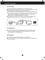
Connecting the stand base or Removing the stand base
1
.
Place the monitor with its front facing downward on a cushion or soft cloth.
2. Align the hooks on the Stand Body with the matching slots in the Stand Base.
3. Insert the hooks into slots.
Slot
Stand Base
Hook
Stand Body
WARNING
The tape and locking pin may only be removed from those monitors equipped with a standing
base when the base is pulled up. Otherwise, you may be injured by the protruding sections of
the stand.
Handle Product with Care. : When you lift up or move the product, Do Not hold or touch the
front part of LCD panel. It will damage the panel. (Please hold the Stand Body or plastic cover of
the product.)

6
Connecting the Display
IMPORTANT
This illustration depicts the general model of connection. Your monitor may differ from the items
shown in the picture.
Do not carry the product upside down holding only the stand base. The product may fall and get
damaged or injure your foot.
4.
Attach the monitor to the Stand Base by turning the screw to the right.
5.
Lift and turn the monitor to face towards the front after the connection is
made to the female part of the cable you're attaching.
6.
Take the screw out by turning to the left to separate the monitor and Stand
Base.
Screw : Turn the screw by using the screw handle.
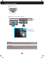
Positioning your display
After installation, adjust the angle as shown below.
1. Adjust the position of the panel in various ways for maximum comfort.
Tilt Range : -6˚ to 22˚
-6
22
When adjusting the angle of the
screen, do not put your finger(s) in
between the head of the monitor
and the stand body. You can hurt
your finger(s).

7
Connecting the Display
Swivel Range : 350˚
350
Height Range : maximum 100.0 mm (3.94 inch)
* Please be sure to
remove the Locking
pin to adjust the height.
100.0 mm
ERGONOMIC
I
t is recommended that in order to maintain an ergonomic and comfortable viewing position, the forward tilt
angle of the monitor should not exceed 5 degrees.
WARNING
You do not need to replace the Locking pin after it is removed, to adjust its height.

8
Connecting the Display
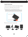
-The pivot function allows you to rotate the screen 90 degrees clockwise.
1.
Lift the monitor to its highest height to utilize the Pivot function.
2. Landscape & Portrait : You can rotate the panel 90
o
clockwise.
Please be cautious and avoid contact between the monitor head and the
Stand Base when rotating the screen to access the Pivot function. If the
monitor head touches the Stand Base, then the Stand Base could crack.
3.
Be careful with the cables when rotating the screen.
Using the Pivot function
Stand section
Head section

* HDMI is optimized for AV equipment.
* HDMI is not for PC use.
Connecting the Display
9
A
B
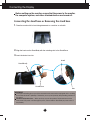
Connect DVI-I Cable
Connect DVI-D Cable
Connect HDMI Cable
1.
Before setting up the monitor, ensure that the power to the monitor, the computer
system, and other attached devices is turned off.
2.
Connect signal input cable and power cord in order, then tighten the screw
of the signal cable.
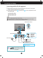
Connecting with the PC/
AV equipment
1
2
Wall-outlet type
Varies according to model.
NOTE
This is a simplified representation of the rear view.
This rear view represents a general model; your display may differ from the view as shown.
The HDMI-DVI cable is not compatible with the DVD player or others.
C
HDMI Headphone Output
AV equipment
(Set-Top Box, DVD,
Video,Video Game Console)
Headphone
/Earphone
Do not connect the commercial
Digital-to-Analog converter to the
DVI-I cable, because it may not
be compatible.
Connect the signal
input cable and
tighten it up by
turning in the
direction of the
arrow as shown in
the figure.

10
Connecting the Display
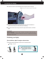
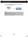
NOTE
‘ Self Image Setting Function’? This function provides the user with optimal display
settings.When the user connects the monitor for the first time, this function automatically adjusts
the display to optimal settings for individual input signals.
‘AUTO/SET’ Function? When you encounter problems such as blurry screen, blurred letters,
screen flicker or tilted screen while using the device or after changing screen resolution, press
the AUTO/SET function button to improve resolution.
3. Press the Power Button ( ) on the front panel to turn the power on. When monitor
power is turned on, the 'Self Image Setting Function' is executed automatically.
(Only for DVI-I analog signal cable input)

11
Connecting the Display
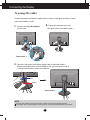
To arrange the cables
Connect the power cord and the signal cable as shown in the figure and then fix them
to the cable holders 1 and 2.
1. Please insert the cable holder1
into the hole.
2. Please put the power cord and
the signal cable in the cable holder 1.
Press
Pull
3. Please put the power cord and the signal cable in the cable holder 2.
While pressing the bottom of cable holder 2 with one hand, pull the top of
it with the other hand as shown in the picture.
Cable holder 2
Cable holder 1
NOTE
Use the cable holder to organize the cables in order to use the pivot function properly.
This picture shows how to organize cables generally and may look different from your product.

12
Connecting the Display
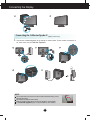
Using True Color Finder Program
Requirements
•
Windows 2000(Service Pack 4 or higher), XP(Service Pack 2 or higher), Vista, Windows 7
• Macintosh OS X(10.0 to 10.5)
1. After installing the monitor hood, insert the CD provided.
2. Click on the [True Color Finder] -> [Installation] icons to install the program. For detailed
method on how to use the program, refer to the True Color Finder manual in the provided CD.
3. After executing the "True Color Finder" program, connect the Calibrator(Spyder3) to the
monitor and computer respectively.
Connecting and Disconnecting the Monitor Hood
(optinal accessory)
1. Connect the Monitor Hood as shown below.
2. To disconnect the monitor hood, follow the steps in the reverse order.
1
2
4
5
6
3
8
7
9
10
12
11
13
1
2
4
5
6
3
8
7
9
10
12
11
13
1
2
4
5
6
3
8
7
9
10
12
11
13
1
2
4
5
6
3
8
7
9
10
12
11
13
After cross inserting, putting
'8' latch into the groove and
pushing it towards an arrow
direction, please assemble
by pressing from number 9
to number 12.
1
13
12
10
9
8
11
6
7
5
4
3
2
1
13
12
10
9
8
11
6
7
5
4
3
2
1
2
4
5
6
3
8
7
9
10
10
12
12
11
11
13
A click will be heard
when the clip engages.
1
2
4
5
6
3
8
7
9
10
12
11
1313
1
13
12
10
9
8
11
6
7
5
4
3
2
1
2
4
5
6
3
8
7
9
10
12
11
13
After inserting '1' latch into
the groove and pushing it
towards an arrow direction,
please assemble by pressing
from number 2 to number 6.
1
2
4
5
6
3
8
7
9
10
12
11
13

13
Connecting the Display
Connecting the Calibrator(Spyder3)
(optinal accessory)
1. Connect the Calibrator(Spyder3) to the monitor as shown below. Tilt the monitor to maximum of
16° to the rear to use the Calibrator (Spyder3).
AUDIO
OUT
1 2
AUDIO
OUT
1 2
1 2
NOTE
Do not put excessive pressure on the monitor hood when fitting. It may
damage the hood.
Do not put any objects on the hood.
With the hood installed, do not shake it or rotate the screen(Pivot).
The Calibrator (Spyder3) may not be provided for some models.
1
13
12
10
9
8
11
6
7
5
4
3
2
1
13
13
12
12
10
10
9
8
8
11
11
6
7
5
4
3
2
1
13
12
10
9
8
11
6
7
5
4
3
2
16

14
Connecting the Display
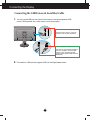
Connecting the USB(Universal Serial Bus) Cable
1. You can use the USB port at the back of the monitor to connect peripherals (USB
mouse, USB keyboard, etc.) to the monitor, not to the computer.
2.
The monitor’s USB terminal supports USB 2.0 and High Speed cables.
1 2
Four USB Downstream ports
Connect these ports to a mouse,
memory stick or USB hard disk.
One USB Upstream port
Connect this port to the downstream
port of a computer, laptop or USB
monitor (Your computer or USB
monitor must support USB and have
USB ports).

15
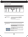
Control Panel Functions
Front Panel Controls
MENU Button
Use this button to enter or exit the On Screen Display.
OSD LOCKED/UNLOCKED
This function allows you to lock the current control settings,
so that they cannot be inadvertently changed. Press and
hold the MENU button for several seconds. The message
"OSD LOCKED" should appear.
You can unlock the OSD controls at any time by pushing the
MENU button for several seconds. The message "OSD
UNLOCKED" should appear.
MODE Button
Use this button to move to items in COLOR MODE
(CUSTOM, sRGB, ADOBE RGB, CALIBRATION,
EMULATION, PLNR).
For more information, refer to page 20 to 21.

16
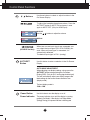
Control Panel Functions
Use this button to enter a selection in the On Screen
Display.
AUTO/SET
Button
AUTO IMAGE ADJUSTMENT
When adjusting your display settings, always press the
AUTO/SET button before entering the On Screen
Display(OSD). (Only for DVI-I analog signal cable input)
This will automatically adjust your display image to the
ideal settings for the current screen resolution size
(display mode).
The best display mode is
1920 x 1200
Buttons
Use these buttons to select or adjust functions in the
On Screen Display.
Use this button to turn the display on or off.
Power Button
When two or more input signals are connected, you
can select the input signal (DVI-I/DVI-D/HDMI) you
want. When only one signal is connected, it is
automatically detected.
The default input signal is DVI-I (analog).
(SOURCE Hot key)
The power indicator stays red if the display is running
properly (On Mode). If the display is in Sleep Mode
(Energy Saving), the power indicator is blinking red.
Power Indicator
Use the buttons to adjust the volume.
To adjust the headphone/earphone volume. Press the
AUTO/SET button to MUTE ON and press it once
again to MUTE OFF. (Only for HDMI input)
MUTE OFF
MUTE ON

17
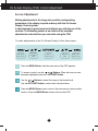
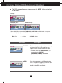
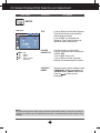
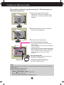
On Screen Display (OSD) Control Adjustment
Screen Adjustment
Making adjustments to the image size, position and operating
parameters of the display is quick and easy with the On Screen
Display Control system.
A short example is given below to familiarize you with the use of the
controls. The following section is an outline of the available
adjustments and selections you can make using the OSD.
Pops up the
menu screen
To make adjustments in the On Screen Display, follow these steps:
Move where
you want to
adjust
Select a
menu icon
Adjust the
status
Exit from the
menu screen.
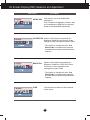
Press the MENU Button, then the main menu of the OSD appears.
To access a control, use the or Buttons. When the icon you want
becomes highlighted, press the AUTO/SET Button.
Use the / Buttons to adjust the image to the desired level.
Use the AUTO/SET Button to select other sub-menu items.
Press the MENU Button once to return to the main menu to select another
function. Press the MENU Button twice to exit from the OSD.
1
2
3
4

18
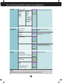
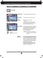
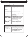
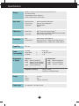
On Screen Display(OSD) Selection and Adjustment
The following table indicates all the On Screen Display control, adjustment,
and setting menus.
Main menu Sub-menu
Supported signals
Description
CUSTOM
sRGB
ADOBE RGB
CALIBRATION
EMULATION
PLNR
COLOR MODE
The default mode that adjusts the
overall range of colors of the RGB
LED panel.
: HDMI (YUV) signal
: HDMI (RGB) signal
HDMI(Y)
HDMI(R)
: DVI-I(Analog) signal
: DVI-I(Digital) signal
: DVI-D(Digital) signal
DVI-I(A)
DVI-I(D)
DVI-D
DVI-I(A)
DVI-I(D)
DVI-D
HDMI(Y)
HDMI(R)
BRIGHTNESS
CONTRAST
GAMMA
BLACK LEVEL
WHITE BALANCE
PICTURE
Standard image settings.
DVI-I(A)
DVI-I(D)
DVI-D
HDMI(Y)
HDMI(R)
DVI-I(A)
HDMI(Y)
HDMI(R)
Adjusts colors based on sRGB.
Adjusts colors based on ADOBE
RGB.
Adjusts Color features by
controlling the Brightness,
WhitePoint and Gamma values
through the color management
system (CMS).
Adjusts Color features by
controlling the Brightness,
WhitePoint , RGB Color Gamut
and Gamma values through the
color management system (CMS).
DVI-I(A)
DVI-I(D)
DVI-D
HDMI(R)
DVI-I(A)
DVI-I(D)
DVI-D
HDMI(R)
DVI-I(A)
DVI-I(D)
DVI-D
DVI-I(A)
DVI-I(D)
DVI-D
DVI-I(A)
DVI-I(D)
DVI-D
HDMI(Y)
HDMI(R)
Color features are pre-set for 255
monotonic gray levels.

19
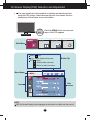
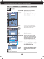
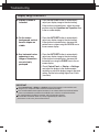
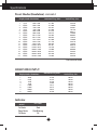
On Screen Display(OSD) Selection and Adjustment
NOTE
The order of icons may differ depending on the model (18 to 27).
LANGUAGE
OSD POSITION
(
HORIZONTAL / VERTICAL)
OVERSCAN
ARC
RTC
POWER INDICATOR
FACTORY RESET
Additional settings
SETUP
HORIZONTAL
VERTICAL
CLOCK
PHASE
SHARPNESS
HORIZONTAL MIRRORING
Adjusts the clarity and stability
of the screen
TRACKING
Adjusts the position of the
screen
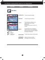
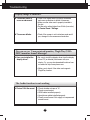
COLOR TEMP
COLOR
Color temperature adjustments
RED
GREEN
BLUE
HUE
SATURATION
SIX COLOR
(RED/GREEN/
BLUE/CYAN/
MAGENTA/
YELLOW)
5000K
6500K
7200K
8200K
9300K
(PRESET) (USER)
COLOR RESET
DVI-I(A)
DVI-I(D)
DVI-D
HDMI(Y)
HDMI(R)
DVI-I(A)
DVI-I(A)
DVI-I(A)
DVI-I(D)
DVI-D
HDMI(Y)
HDMI(R)
DVI-I(A)
DVI-I(D)
DVI-D
HDMI(Y)
HDMI(R)
HDMI(Y)
HDMI(R)
DVI-I(A)
DVI-I(D)
DVI-D
HDMI(Y)
HDMI(R)
DVI-I(A)
DVI-I(D)
DVI-D
HDMI(Y)
HDMI(R)
To adjust to set the image
mirroring(horizontal inversion).
Page is loading ...
Page is loading ...
Page is loading ...
Page is loading ...
Page is loading ...
Page is loading ...
Page is loading ...
Page is loading ...
Page is loading ...
Page is loading ...
Page is loading ...
Page is loading ...
Page is loading ...
Page is loading ...
Page is loading ...
Page is loading ...
-
 1
1
-
 2
2
-
 3
3
-
 4
4
-
 5
5
-
 6
6
-
 7
7
-
 8
8
-
 9
9
-
 10
10
-
 11
11
-
 12
12
-
 13
13
-
 14
14
-
 15
15
-
 16
16
-
 17
17
-
 18
18
-
 19
19
-
 20
20
-
 21
21
-
 22
22
-
 23
23
-
 24
24
-
 25
25
-
 26
26
-
 27
27
-
 28
28
-
 29
29
-
 30
30
-
 31
31
-
 32
32
-
 33
33
-
 34
34
-
 35
35
-
 36
36


Planar Systems PX2491W User manual
- Category
- LED displays
- Type
- User manual
Ask a question and I''ll find the answer in the document
Finding information in a document is now easier with AI