Maytag MGD5700TQ - Swing Door Dryer Specification

Category
Electric laundry dryers
Type
Specification

This manual is also suitable for

Gas Dryer
PRODUCT MODEL NUMBERS
W10562360A
02/2105
MGDC300B, MGDC400B, MGDX500B, MGDC555D, MGDX655D,
MGDC215E, MGDC415E
29" Wide Models
Dryer Dimensions
A B
22
3
/4"
(578 mm)
27
3
/4"
(705 mm)
A. Wide opening side-swing door
B. Wide opening hamper door
NOTE: Leveling legs should be 1/2" (13 mm) (to match height of
3.6 cu. ft. capacity washer) or 1½" (38 mm) (to match height of
3.8 cu. ft. capacity washer).
29"
(737 mm)
43
3
/8"
(1102 mm)
1
/2"
(13 mm)
29"
(737 mm)
1
1
/2"
(38 mm)
43
3
/8"
(1102 mm)
Installation Spacing
A
B
C
18"*
(457 mm)
1"
(25 mm)
29"
(737 mm)
1"
(25 mm)
1"*
(25 mm)
14" max.*
(356 mm)
27¾"
(705 mm)
48 in.
(310 cm )
2
*
2
3"*
(76 mm)
3"*
(76 mm)
24 in.
(155 cm )
2
*
2
A. Recessed area
B. Side view – closet or conned area
C. Closet door with vents
*Required spacing
27" Wide Models
Dryer Dimensions
A B
22
3
/4"
(578 mm)
29
1
/2"
(749 mm)
13
3
/4"
(349 mm)
29
1
/2"
(749 mm)
A. Wide opening side-swing door
B. Wide opening hamper door
27"
(686 mm)
1
1
/2"
(38 mm)
43"
(1092 mm)
Installation Spacing
A
B
C
18"*
(457 mm)
1"
(25 mm)
27"
(686 mm)
1"
(25 mm)
1"*
(25 mm)
14" max.*
(356 mm)
29
½
"
(749 mm)
5
½"*
(140 mm)
48 in.
(310 cm )
2
*
2
24 in.
(155 cm )
2
*
2
3"*
(76 mm)
3"*
(76 mm)
A. Recessed area
B. Side view – closet or conned area
C. Closet door with vents
*Required spacing
27
3
/4"
(705 mm)
13
3
/4"
(349 mm)
ELECTRICAL REQUIREMENTS
A 120-volt, 60 Hz, AC-only, 15 or 20 amp fused electrical supply is required. A time-delay fuse or circuit breaker and a separate circuit
are recommended.
GAS SUPPLY REQUIREMENTS
Gas supply: This dryer is equipped for use with Natural gas. Dryer can be converted to L.P. gas. When rigid pipe is used it should be 1/2" IPS. When
acceptable to the gas supplier and local codes, 3/8" approved tubing may be used for lengths under 20 ft (6.1 m). For lengths over 20 ft (6.1 m), larger
tubing should be used. Pipe-joint compounds resistant to the action of L.P. gas must be used. An individual manual shutoff valve must be installed
within 6 ft (1.8 m) of the dryer in accordance with the National Fuel Gas Code ANSI Z223.1.
INSTALLATION REQUIREMENTS
Installation clearances:
The location must be large enough to allow the dryer door to
open fully.
Most installations require a minimum 5½" (140 mm) clearance
behind the dryer for the exhaust vent with elbow. See “Venting
Requirements.”
Installation spacing for recessed area or closet
The dimensions shown are for the minimum spacing allowed.
Additional spacing should be considered for ease of installation
and servicing.
Additional clearances might be required for wall, door, and oor
moldings.
Additional spacing of 1" (25 mm) on all sides of the dryer is
recommended to reduce noise transfer.
For closet installation, with a door, minimum ventilation
openings in the top and bottom of the door are required.
Louvered doors with equivalent ventilation openings are
acceptable.
Companion appliance spacing should also be considered.
Because Whirlpool Corporation policy includes a continuous commitment to improve Dimensions are for planning purposes only. For complete details, see Installation
our products, we reserve the right to change materials and specications without notice. Instructions packed with product. Specications subject to change without notice.
VENTING REQUIREMENTS
Exhaust venting: Exhaust your dryer to the outside. 4" (102 mm)
diameter vent is required. Rigid or exible metal exhaust vent
must be used. Do not use plastic or metal foil vet. Exhaust hood
must be at least 12" (305 mm) from the ground or any object that
may be in the path of the exhaust.
Determine vent length and elbows needed for best
drying performance:
Use following Vent System Chart to determine type of vent
material and hood combinations acceptable to use.
NOTE: Do not use vent runs longer than those specied
in Vent System Chart. Exhaust systems longer than those
specied will:
Shorten life of dryer.
Reduce performance, resulting in longer drying times
and increased energy usage.
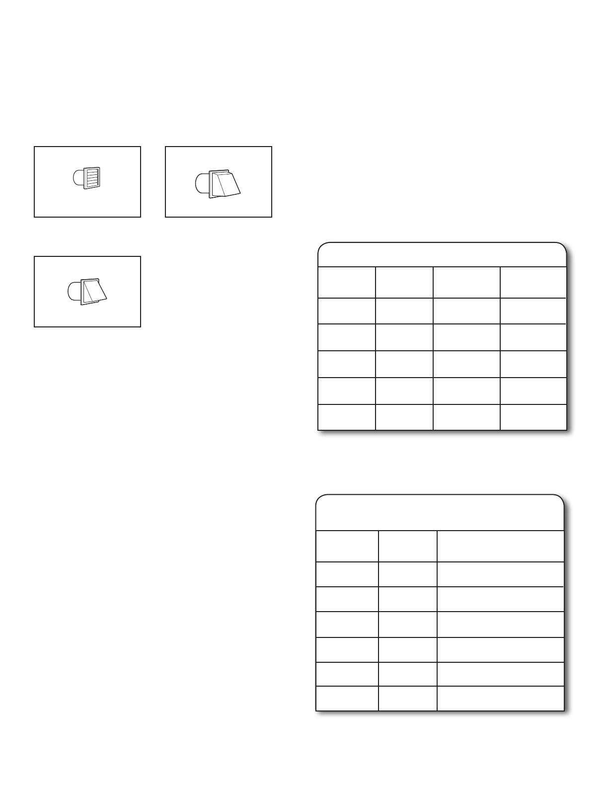
Louvered Hood
Angled Hood
Box Hood
Exhaust hoods:
Recommended Styles:
Acceptable Style:
Determine vent path:
Select route that will provide straightest and most direct
path outdoors.
Plan installation to use fewest number of elbows and turns.
When using elbows or making turns, allow as much room
as possible.
Bend vent gradually to avoid kinking.
Use as few 90° turns as possible.
Vent System Chart
Number of
90° turns or
elbows
Type
of vent
Box/louvered
hoods
Angled
hoods
1
4
3
2
0
Rigid metal
Rigid metal
Rigid metal
Rigid metal
Rigid metal
64 ft. (20 m)
54 ft. (16.5 m)
44 ft. (13.4 m)
35 ft. (10.7 m)
27 ft. (8.2 m)
58 ft. (17.7 m)
48 ft. (14.6 m)
38 ft. (11.6 m)
29 ft. (8.8 m)
21 ft. (6.4 m)
NOTE: Side and bottom exhaust installations for 27" wide
models have a 90º turn inside the dryer. To determine
maximum exhaust length, add one 90º turn to the chart.
Vent System Chart
(29" Wide Long Vent Models Only)
Number of
90° turns
or elbows
Type
of vent
Box/louvered, or
Angled hoods
1
4
3
2
0 Rigid metal 120 ft. (36.6 m)
110 ft. (33.5 m)
100 ft. (30.5 m)
90 ft. (27.4 m)
80 ft. (24.4 m)
Rigid metal
Rigid metal
Rigid metal
Rigid metal
5 70 ft. (21.3 m)Rigid metal
The “Vent System Chart” provides venting requirements that will
help achieve best drying performance.
  • Page 1 1
  • Page 2 2
  • Page 3 3

Maytag MGD5700TQ - Swing Door Dryer Specification

Category
Electric laundry dryers
Type
Specification
This manual is also suitable for

Ask a question and I''ll find the answer in the document

Finding information in a document is now easier with AI