Simplicity 95288E (1694994) Owner's manual
- Category
- Snow throwers
- Type
- Owner's manual

Bimplicilq
OPERATOR'S
MANUAl
Large Frame
Snowthrowers
8526 Models
Mfg. No. Description
1694984 L8526E, 8.5HP Snowthrower
1695082 L8526EX, 8.5HP Snowthrower (CE)
1694993 85268E, 8.5HP Snowthrower
1695093 E85268E, 8.5HP Snowthrower (CE)
9528 Models
Mfg. No. Description
1694985 L9528E, 9.5HP Snowthrower
1695083 L9528EX, 9.5HP Snowthrower (CE)
1694994 95288E, 9.5HP Snowthrower
1695094 E95288E, 9.5HP Snowthrower (CE)
10530 Models
Mfg. No. Description
1694986 L10530E, 10.5HP Snowthrower
1695084 L10530EX, 10.5HP Snowthrower (CE)
1694995 105308E, 10.5HP Snowthrower
1695095 E105308E, 10.5HP Snowthrower (CE)
11 532
Mfg. No.
1694987
1694996
1695096
Models
Description
L11532E, 11.5HP Snowthrower
115328E, 11.5HP Snowthrower
E115328E, 11.5HP Snowthrower (CE)
1733286
Revision 00
Rev. Date 8/2006
TP 100-4339-00-LW-SN

TableofContents
CONTENTS:
Safety Rules & Information
General ............................................................ 2
Training ............................................................ 4
Preparation ...................................................... 4
Operation ......................................................... 4
Children ........................................................... 5
Clearing a Clogged Discharge Chute .............. 5
Service, Maintenance and Storage ................. 5
Emissions ........................................................ 3
Decals .............................................................. 6
Safety Icons ..................................................... 8
Identification Numbers ........................................ 9
Features, Controls, & Operation
Control Locations ........................................... 10
General Operation
Checks Before Each Start-Up ....................... 12
Starting Controls ............................................ 13
Starting the Engine ........................................ 14
Operating The Snowthrower .......................... 14
Clearing a Clogged Discharge Chute ............ 14
Ground Speed Selector ................................. 15
Engine Speed ................................................ 15
Deflector ........................................................ 15
Scraper Bar & Skid Shoes ............................. 15
Easy-Turn and Traction Drive Lock ................ 16
After Each Use .............................................. 17
Storage .......................................................... 17
Regular Maintenance
Schedule ........................................................ 18
Checking Tire Pressure ................................. 18
Auger Gear Case Lubrication ........................ 18
Lubrication ..................................................... 19
Check/Lubricate Free-Hand Linkage ........... 20
Lubricate the Auger Shaft & Assembly .......... 20
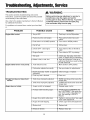
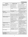
Troubleshooting, Adjustments, & Service
Troubleshooting ............................................. 22
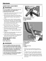
Speed Selector Adjustment ........................... 24
Auger Drive Cable Adjustment ...................... 24
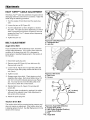
Traction Drive Adjustment .............................. 25
Easy Turn Cable Adjustment ......................... 26
Belt Adjustment ............................................. 26
Shear Pin Replacement ................................. 27
Belt Guide Adjustment ................................... 27
Belt Replacement .......................................... 28
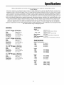
Specifications .................................................... 31
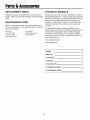
Replacement Parts & Accessories ................. 32
WARNING
You must read, understand and comply with all
safety and operating instructions in this manual
before attempting to set-up and operate your
snowthrower.
Failure to comply with all safety and operating
instructions can result in loss of machine control,
serious personal injury to you and/or
bystanders, and risk of equipment and property
damage. The triangle in the text signifies
important cautions or warnings which must be
followed.
WARNING
Engine exhaust from this product contains
chemicals known, in certain quantities, to cause
cancer, birth defects, or other reproductive harm,

Rules& information
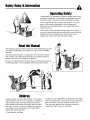
OperatingSafety
Congratulations on purchasing a superior-quality piece of lawn
and garden equipment. Our products are designed and manu-
factured to meet or exceed all industry standards for safety.
Power equipment is only as safe as the operator. If it is mis-
used, or not properly maintained, it can be dangerous!
Remember, you are responsible for your safety and that of
those around you.
Use common sense, and think through what you are doing. If
you are not sure that the task you are about to perform can be
safely done with the equipment you have chosen, ask a
professional: contact your local authorized dealer.
Readthe Manual
The operator's manual contains important safety information you need
to be aware of BEFORE you operate your unit as well as DURING
operation.
Safe operating techniques, an explanation of the product's features
and controls, and maintenance information is included to help you
get the most out of your equipment investment.
Be sure to completely read the Safety Rules and Information found on
the following pages. Also completely read the Operation section.
Children
Tragic accidents can occur with children. Do not allow
them anywhere near the area of operation. Children are
often attracted to the unit and snowthrowing activity.
Never assume that children will remain where you last
saw them. If there is a risk that children may enter the
area where you are operating the unit, have another
responsible adult watch them.
TP 600-3606-05-LW-SMA
DO NOT ALLOW CHILDREN TO OPERATE THIS UNIT!
This encourages them to come near the unit in the future
while it is running, and they could be seriously hurt.
They may then approach the unit when you are not
expecting it, and you may run over them.

SafetyRulesandinformation,
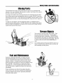
MovingParts
This equipment has many moving parts that can injure you or someone else.
However, if you are standing in the operator's position, and follow all the rules in
this book, the unit is safe to operate.
The auger and impeller have spinning parts that can amputate hands and feet.
Do not allow anyone near the equipment while it is running! DO NOT clear the
discharge chute by hand. If the chute becomes plugged, stop the engine, wait for
all moving parts to stop, and clear the blockage with a clean-out tool or piece of
wood.
To help you, the operator, use this equipment safely, it is equipped with an
operator-present safety system. Do NOT attempt to alter or bypass the system.
See your dealer immediately if the system does not pass all the safety interlock
system tests found in this manual.
ThrownObjects
This unit has a spinning auger and impeller. They
pick up and throw snow and ice. Thrown debris
could seriously injure a bystander. ALWAYS direct
the discharge chute away from bystanders and prop-
erty that could be damaged by frying debris. Be sure
to clean up the area to be cleared BEFORE you
start.
Do not allow anyone in the area while the unit is run-
ning! If someone does enter the area, shut the unit
off immediately until they leave.
FuelandMaintenance
Gasoline is extremely flammable. Its vapors are also
extremely flammable and can travel to distant ignition
sources. Gasoline must only be used as a fuel, not as a
solvent or cleaner. It should never be stored any place
where its vapors can build up or travel to an ignition source
like a pilot light. Fuel belongs in an approved, plastic,
sealed gas can, or in the snowthrower fuel tank with the
cap securely closed. Spilled fuel needs to be cleaned up
immediately.
Proper maintenance is critical to the safety and perfor-
mance of your unit. Be sure to perform the maintenance
procedures listed in this manual, especially periodically
testing the safety system.
3

SafetyRules& information
TRAINING
1. Read, understand, and follow all instructions on the
machine and in the manuals before operating this
unit. Be thoroughly familiar with the controls and the
proper use of the equipment. Know how to stop the
unit and disengage the controls quickly.
2. Never allow children to operate the equipment.
Never allow adults to operate the equipment without
proper instruction.
3. Keep the area of operation clear of all persons, partic-
ularly small children and pets.
4. Exercise caution to avoid slipping or falling especially
when operating in reverse.
This machine is capable to amputating hands and feet and throwing objects. Read these safety rules and
follow them closely. Failure to obey these rules could result in loss of control of unit, severe personal injury
or death to you, or bystanders, or damage to property or equipment. The triangle ,_ in text signifies
important cautions or warnings which must be followed.
PREPARATION
1. Thoroughly inspect the area where the equipment is
to be used and remove all doormat, sleds, boards,
wires, and other foreign objects.
2. Disengage all clutches and shift into neutral before
starting engine (motor).
3. Do not operate the equipment without wearing ade-
quate winter outer garments. Wear footwear that will
improve footing on slippery surfaces. Avoid loose fit-
ting clothing that can get caught in moving parts.
4. Handle fuel with care; it is highly flammable.
(a) Use an approved fuel container.
(b) Never add fuel to a running engine or hot engine.
(c) Fill fuel tank outdoors with extreme care. Never fill
fuel tank indoors. Replace fuel cap securely and
wipe up spilled fuel.
(d) Never fill containers inside a vehicle or on a truck
or trailer bed with a plastic liner. Always place con-
tainers on the ground, away from your vehicle, before
filling.
(e) When practical, remove gas-powered equipment
from the truck or trailer and refuel it on the ground. If
this is not possible, then refuel such on a trailer with a
portable container, rather than from a gasoline dis-
penser nozzle.
(f) Keep nozzle in contact with the rim of the fuel tank
or container opening at all times, until refueling is
complete. Do not use a nozzle lock-open device.
(g) Replace gasoline cap securely and wipe up spilled
fuel.
(h) If fuel is spilled on clothing, change clothing imme-
diately.
5. Use extension cords and receptacles as specified by
the manufacturer for all units with electric drive
motors or electric starting motors.
6. Adjust the collector housing height to clear gravel or
crushed rock surfaces.
7. Never attempt to make any adjustments while the
engine (motor) is running (except when specifically
recommended by the manufacturer).
8. Let engine (motor) and machine adjust to outdoor
temperatures before starting to clear snow.
9. Always wear safety glasses or eye shields during
operation or while performing an adjustment or repair
to protect eye from foreign objects that may be
thrown from the machine.
OPERATION
1. Do not put hands or feet near or under rotating parts.
Keep clear of the discharge opening at all times.
2. Exercise extreme caution when operating on or
crossing gravel drives, walks, or roads. Stay alert for
hidden hazards or traffic.
3. After striking a foreign object, stop the engine (motor),
remove the wire from the spark plug, disconnect the
cord on electric motors, thoroughly inspect the
snowthrower for any damage, and repair the damage
before restarting and operating the snowthrower.
4. If the unit should start to vibrate abnormally, stop the
engine (motor) and check immediately for the cause.
Vibration is generally a warning of trouble.
5. Stop the engine (motor) whenever you leave the
operating position, before unclogging the
collector/impeller housing or discharge guide, and
when making any repairs, adjustments, or inspec-
tions.
6. When cleaning, repairing, or inspecting make certain
the collector/impeller and all moving parts have
stopped. Disconnect the spark plug wire and keep
the wire away from the plug to prevent accidental
starting.
7. Do not run the engine indoors except for starting the
engine or for transporting the snowthrower in or out of
the building. Open the outside doors; exhaust fumes
are dangerous.
8. Exercise extreme caution when operating on slopes.
Do not attempt to clear steep slopes.
9. Never operate the snowthrower without proper
guards plates, or other safety protective devices in
place and working.
10. Never direct the discharge toward people or areas
where property damage can occur. Keep children
and others away.
11. Do not overload the machine capacity by attempting
to clear snow at too fast a rate.
12. Never operate the machine at high transport speeds
on slippery surfaces. Look behind and use care
when operating in reverse.
13. Disengage power to the collector/impeller when
snowthrower is transported or not in use.
14. Use only attachments and accessories approved by
the manufacturer of the snowthrower (such as wheel
weights, counterweights, or cabs).
15. Never operate the snowthrower without good visibility
or light. Always be sure of your footing, and keep a
firm hold on the handles. Walk, never run.
16. Never touch a hot engine or muffler.
17. Never operate the snowthrower near glass enclo-
sures, automobiles, window wells, drop-offs, and the
like without proper adjustment of the discharge angle.
18. Never direct discharge at bystanders or allow anyone
in front of the unit.
19. Never leave a running unit unattended. Always disen-
gage the auger and traction controls, stop engine,
and remove keys.
20. Do not operate the unit while under the influence of
alcohol or drugs.

21.Keepinmindtheoperatorisresponsibleforacci-
dentsoccurringtootherpeopleorproperty.
22.Dataindicatesthatoperators,age60yearsand
above,areinvolvedinalargepercentageofpower
equipment-relatedinjuries.Theseoperatorsshould
evaluatetheirabilitytooperatetheunitsafelyenough
toprotectthemselvesandothersfrominjury.
23.DONOTwearlongscarvesorlooseclothingthat
couldbecomeentangledinmovingparts.
24.Snowcanhideobstacles.Makesuretoremoveall
obstaclesfromtheareatobecleared.
CHILDREN
Tragic accidents can occur if the operator is not alert to the
presence of children. Children are often attracted to the
unit and the operating activity. Never assume that children
will remain where you last saw them.
1. Keep children out of the area and under the watchful
care of another responsible adult.
2. Be alert and turn unit off if children enter the area.
3. Never allow children to operate the unit.
4. Use extra care when approaching blind corners,
shrubs, trees, or other objects that may obscure
vision.
CLEARING A CLOGGED DISCHARGE
CHUTE
Hand contact with the rotating impeller inside the dis-
charge chute is the most common cause of injury associ-
ated with snowthrowers. Never use your hand to clean
out the discharge chute.
To clear the chute:
1. SHUT OFF THE ENGINE.
2. Wait 10 seconds to be sure the impeller blades have
stopped rotating.
3. Always use a clean out tool, not your hands.
SERVICE, MAINTENANCE, AND STORAGE
1. Check shear bolts and other bolts at frequent inter-
vals for proper tightness to be sure the equipment is
in safe working condition.
2. Never store the machine with fuel in the fuel tank
inside a building where ignition sources are present
such as hot water and spacer heaters, or clothes dry-
ers. Allow the engine to cool before storing in any
enclosure.
3. Always refer to the operator's manual for important
details if the snowthrower is to be stored for an
extended period.
4. Maintain or replace safety and instruction labels as
necessary.
5. Run the machine a few minutes after throwing snow
to prevent freeze-up of the collector/impeller.
6. If fuel is spilled, do not attempt to start the engine but
move the machine away from the area of spillage and
avoid creating any source of ignition until fuel vapors
have dissipated.
7. Always observe safe refueling and fuel handling prac-
tices when refueling the unit after transportation or
storage.
Safety Rules
8. Always follow the engine manual instructions for stor-
age preparations before storing the unit for both short
and long term periods.
9. Always follow the engine manual instructions for
proper start-up procedures when returning the unit to
service.
10. Maintain or replace safety and instruction labels as
necessary.
11. Keep nuts and bolts tight and keep equipment in
good condition.
12. Never tamper with safety devices. Check their proper
operation regularly and make necessary repairs if
they are not functioning properly.
13.Components are subject to wear, damage, and dete-
rioration. Frequently check components and replace
with manufacturer's recommended parts, when nec-
essary.
14.Check control operation frequently. Adjust and ser-
vice as required.
15. Use only factory authorized replacement parts when
making repairs.
16.Always comply with factory specifications on all set-
tings and adjustments.
17.Only authorized service locations should be utilized
for major service and repair requirements.
18. Never attempt to make major repairs on this unit
unless you have been properly trained. Improper ser-
vice procedures can result in hazardous operation,
equipment damage and voiding of manufacturer's
warranty.
19.Check shear bolts and other bolts at frequent inter-
vals for proper tightness to be sure the equipment is
in safe working condition.
EMISSIONS
1. Engine exhaust from this product contains chemicals
known, in certain quantities, to cause cancer, birth
defects, or other reproductive harm.
2. If available, look for the relevant Emissions Durability
Period and Air Index information on the engine emis-
sions label.
IGNITION SYSTEM
1. This spark ignition system complies with Canadian
ICES-002.
5

Decals
DECALS
This unit has been designed and manufactured to pro-
vide you with the safety and reliability you would expect
from an industry leader in outdoor power equipment.
Although reading this manual and safety instructions it
contains will provide you with the necessary basic knowl-
edge to operate this equipment safely and effectively, we
have placed several safety labels on the unit to remind
you of this important information while you are operating
your unit.
All WARNING, CAUTION, and instructional messages
on your unit should be carefully read and obeyed.
Personal bodily injury can result when these instructions
are not followed. The information is for your safety and it
is important.
The safety decals below are on your unit.
If any of these decals are lost or damaged, replace them
at once. See your local dealer for replacements.
These labels are easily applied and will act as a constant
visual reminder to you, and others who may use the
equipment, to follow the safety instructions necessary for
safe, effective, operation.
NOTE: Engine operation and safety decals are supplied
by the engine manufacturer.
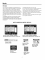
NORTH AMERICAN MODEL DECALS
Part No. 1733033- DANGER/WARNING
Main Dash Decal, North American, w/Easy Turn
Part No. 1733056 - DANGER/WARNING
Main Dash Decal, North American, w/o Easy Turn
The lubricationpoints sh0vm hererflustbe lul_ri_ted J iwith 30weig{lt oil every 10h0u[s of operation and
. . before tlSJllg the unit after storage Failtlre t0 iubrigate
ma_osuse amalfunctJ011oftile safety system
Part No. 1733526
Lubrication Decal
Amputationhazard
...................I
_,_ ser10u81n_u_
...........................
Part No. 1716532
Auger Danger
Decal
Part No. 1733057
Discharge Chute
Danger Decal
Part No. 728183
Important
Over Adjustment
Part No. 725432
Belt Stretch &
Adjust

Decals
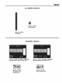
ALL MODEL DECALS
Part No. 1733443
Chute Release
Part No. 1732618
Shift Decal
CE MODEL DECALS
Part No. 1733059 - DANGER / WARNING
Main Dash Decal, CE, w/o Easy Turn
Part No. 1733060 - DANGER/WARNING
Main Dash Decal, CE, w/Easy Turn
Part No. 1727207
Discharge Chute
Danger Decal
Part No. 1727208
Auger Danger Decal
7

Safety icons
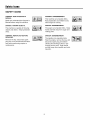
SAFETY ICONS
WARNING: READOPERATOR'S
MANUAL.
Read and understand the Operator's
Manual before using this machine.
DANGER: THROWN OBJECTS.
This machine is capable of throwing
objects and debris. Keep bystanders
away.
WARNING: DISMEMBERMENT.
This machine can amputate limbs.
Keep bystanders and children away
when engine is running.
DANGER: DISMEMBERMENT.
The auger can amputate limbs. Keep
hands and feet away from auger and
rotating parts.
WARNING: REMOVE KEY BEFORE
SERVICING.
Remove the key, disconnect spark
plug wire, and consult technical litera-
ture before performing repairs or
maintenance.
DANGER: DISMEMBERMENT.
The impeller can amputate limbs.
Stop the engine, remove the key, and
disconnect spark plug wire before
clearing the discharge chute or per-
forming service work. Keep hands
and feet away from impeller and rotat-
ing parts.

Identification Numbers
i_piicity Manufacturing, inc.
_ingt0n, Wl 53074-0997 USA
IllililllliJllllilJiiF_llilllllllil
North American /
CE Models
CE Models
(Only)
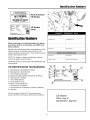
IdentificationNumbers
When contacting your authorized dealer for replace-
ment parts, service, or information you MUST have
these numbers.
Record your model name/number, manufacturer's identi-
fication numbers, and engine serial numbers in the
space provided for easy access. These numbers can be
found in the locations shown.
NOTE: For location of engine identification numbers,
refer to the engine owner's manual.
CE Models: Place the extra copy of the identification tag
in the manual
CE IDENTIFICATION TAG MARKINGS
A. Manufacturer's Identification Number
B. Manufacturer's Serial Number
C. Power Rating in Kilowatts
D. Maximum Engine Speed in Rotations per Minute
E. Manufacturer's Address
F. Year of Manufacture
G. CE Compliance Logo
H. Mass of Unit in Kilograms
I. Sound Power in Decibels
J. Sound Pressure at Operator's Position in Decibels
K. Vibration
This unit complies with ISO 8437, European Machinery
Directive 98/37/EC, and European EMC Directive 89/336/EC.
Model Description Name/Number
Unit MFGNumber Unit SERIAL Number
Dealer Name Date Purchased
EngineMake EngineModel
Engine Type/Spec Engine Code/Serial Number
Mfg..o.: x2xSxxx"_gg6k Serial No.:
_kW: XXX
= Engine RPM XXXX
LpA: XXX dB(A)
- Vibration: XXX m/s 2
Simplicity Mfg, Jnc,
_'Port Washington, Wl USA 53074=0997
CE Models:
Place copy of
Identification Tag here.
9

Features,Controls,& Operation
Please take a moment
and familiarize
yourself with the
name, location, and
function of these
controls so that you will
better understand the
safety and operating
instructions provided in
this manual
1_2==
I
0
/
CONTROL LOCATIONS
The information below briefly describes the function of individual controls. Starting, stopping, and driving require the
combined use of several controls appfied in specific sequences. To learn what combination and sequence of controls
to use for various tasks see the OPERATION section.
1_2=.
Speed Selector
Selects forward speeds 1-6 and reverse speeds 1-2. No
neutral position or gate is required, since the traction
drive design automatically provides "neutral" (no forward
or reverse movement), whenever the Drive Control is
released.
sL_ Traction Control / Free Hand TM Lock
Engages traction drive to wheels when depressed. Also
locks auger control when depressed simultaneously.
Releasing the traction control lever releases the Free
Hand TM auger control lock and stops the drive wheels
and auger.
10

Features & Controls
_ Auger Control
Engages the auger/impeller when depressed.
the control stops the auger/impeller.
Releasing
_ Chute Direction Control
Push the lever forward to unlock the rotator control.
Moving the lever to the left will turn the spout to the left
side and moving the lever to the right will rotate the spout
to the right side. Releasing the lever locks the spout in
position.
/L_& Remote Deflector Control
Chute Deflector: Locks chute deflector in desired posi-
tion. Tilting the chute deflector UP provides a higher
stream and greater distance, while tilting the deflector
DOWN provides a lower stream and less distance.
'08_' Easy Turn TM Control
Easy Turn Control: Engaging the Easy Turn TM lever
releases the leftwheel to allow easy turning in tight
areas. Releasing the control automatically engages both
drive wheels for full traction.
Traction Lock Pins: (8.5HP Models Only) The right
traction wheel can be completely released using the
locking pin (see Figure 7). This allows the unit to be eas-
ily moved with the engine off.
Stop Switch (Power Built Models Only)
Turn the the switch to the ON position to operate the
engine. Turn the switch to the OFF position to stop the
engine.
(_ Starter
Electric Start: Depressing the starter button activates
the electric starter. The electric start button operates on
120 Volts AC, which is provided by connection to the
extension cord provided. Connect this extension cord
ONLY to a properly grounded 3 prong electrical outlet.
Recoil Starter (All Models): Pulling the recoil handle
cranks the engine.
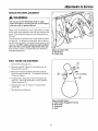
J_ Fuel
Fuel tank filler cap (see illustration). Note: The fuel shut
off valve is located under the fuel tank or on the front of
the engine. Close the valve when the snowthrower is not
in use. Open the valve before starting.
I":-_- Primer Button
When pressed, the primer button provides initialfuel to
help start a cold engine. Normally, pressing the primer
button twice will provide enough fuel to start a cold
engine.
Throttle Lever (Intek Models Only)
Controls engine speed. Move toward the hare icon for
faster engine speed, move toward the turtle icon for
slower engine speed. Move the throttle all the way to
STOP to stop the engine. Set throttle to FAST (hare
icon) for operation.
Engine Key
The engine key prevents the engine from being started.
The key must be fully inserted into the key slot for the
unit to start. The key can also used to stop the engine by
pulling the key out of the key slot.
I",1 Choke Knob
The choke knob adjusts the air/fuel mixture, and is used
to help start a cold engine by providing a richer mixture.
Once the engine is warm and running smoothly, the
choke knob should be set to the off position to provide a
normal air/fuel mix.
----C)Headlight (Select Models, Not Pictured)
The headlight ison at all times when the engine is run-
ning.
11

Operation
GENERAL OPERATION
CHECKS BEFORE EACH START-UP
1. Make sure all safety guards are in place and all nuts,
bolts and clips are secure.
2. Check to make sure that the clean-out is attached to
the auger housing. Do not operate the machine with-
out the clean-out tool properly stored on the auger
housing.
3. Check the engine oil level. See your engine owner's
manual for procedure and specifications.
4. Check to make sure spark plug wire is attached and
spark plug is tightened securely. If necessary, torque
spark plug to 15 ft. Ibs.
5. Check the fuel supply. Fill the tank no closer than 1/4
to 1/2 inch of top of tank to provide space for expan-
sion. See your engine owner's manual for fuel recom-
mendations.
6. Check the scraper bar to make sure it is set at the
desired height. Adjust the skid shoes if necessary.
7. Check the drive control (B, Figure 2), and auger con-
trol (C) for proper operation. Ifadjustment is required,
see the service section for procedures.
8. Check the chute direction control (D, Figure 2) for
proper operation. The discharge chute should rotate
freely in both directions. See the service section for
adjustment procedures and troubleshooting.
9. Check the chute deflector (E, Figure 2) for proper
operation. The deflector should pivot freely up and
down.
10. Position the chute at the desired starting direction
and set the deflector at the desired angle.
11. Check the speed selector (A, Figure 2) for smooth
operation. The control must move freely into each
speed position gate and remain in position when
released. If the speed selector does not move freely
into all forward and reverse speed positions, contact
your local authorized dealer for assistance.
WARNING
This unit is a "two-stage" snowthrower.
The first stage is the auger, which feeds the snow
back into the impeller housing. The second stage
is the impeller, which throws the snow out the
discharge chute. If bodily contact is made with
the auger or impeller when they are rotating,
severe personal injury will occur.
To avoid injury, keep others and yourself away
from the auger and the discharge chute whenever
the engine is running. Read and follow all of the
safety rules and warnings in this manual.
DANGER
Do not clean out discharge chute with hands.
Contact with moving parts inside chute will
cause serious injury. Use clean out tool provided
with machine. Use the following procedure to
remove objects or clear the chute:
1. Stop the engine. Remove the key
2. Wait 10 seconds to be sure the auger/impeller
blades have stopped rotating.
3. Always use the clean-out tool. DO NOT use your
hands.
, WARNING
For your safety, operation on slopes should be in
an up and down direction only. If it becomes
necessary to move across the face of a slope, use
caution and do not blow snow. Be very careful
when changing direction on a slope.
Proper winter footwear is recommended for the
operator to help prevent slipping. Never attempt
to clean snow from excessively steep slopes. The
maximum slope for any operation is 17.7% (10°).
WARNING
Gasoline is highly flammable and must be
handled with care. Never fill the tank when the
engine is hot or running. Always move outdoors
to fill the tank. Keep snowthrower and gasoline
away from open flame or spark.
12

Operation
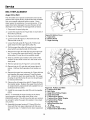
STARTING CONTROLS
See Figure 1 for the following instructions.
Electric Start
A. Electric Start Button - The Electric Start Button
(A) activates an electric starter mounted to the
engine, eliminating the need to pull the starter han-
dle. The Electric Start Button operates on 120 Volts
AC, which is provided by connection to the extension
cord provided with units equipped with this feature.
Connect this extension cord ONLY to a properly
grounded 3 prong electrical outlet.
Manual Start
B. Fuel Valve - (Intek Models) The fuel valve (B) is
located under the fuel tank. It is used to turn the fuel
supply off for out-of-season storage.
C. Starter Handle - The starter handle (C) connects to a
starter cord to manually start the engine. Pulling
starter handle rapidly spins the engine crankshaft,
cycles the engine, and generates the spark neces-
sary for starting the engine.
D. Primer Button - When pressed, the primer button
(D) provides initial fuel to help start a cold engine.
Normally, pressing the primer button twice will pro-
vide enough fuel to start a cold engine.
E. Throttle Lever - (Intek Models)The throttle lever (E)
controls the engine speed. For best overall perfor-
mance, the throttle lever should be set to the FAST
position. Use the SLOW position only for warming the
engine, or to help prevent snow/ice freeze-up when
shutting the unit down for the day.
F. Engine Key - The engine key (F) prevents the
engine from being started by unauthorized individu-
als. The key must be fully inserted into the key slot
for the unit to start. The key is also used to stop the
engine by pulling the key out of the key slot.
G. Choke Knob - The choke knob (G) adjusts the
air/fuel mixture, and is used to help start a cold
engine by providing a richer mixture. Once the engine
is warm and running smoothly, the choke knob
should be set to the off position to provide a normal
air/fuel mix.
H. Stop Switch - (Power Built Models) Switch to the
ON position to operate the engine. Switch to the
OFF position to stop the engine.
@-_
Intek
Model
Power
Built
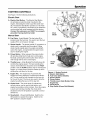
Figures 1. Engine Controls
A. Electric Start Button
B. Fuel Valve (Select Models)
C. Starter Handle
D. Primer Button
E. Throttle Lever (Intek Models Only)
F. Engine Key
G. Choke Knob
H. Stop Switch (Power Built Models)
13

Operation
STARTING THE ENGINE
1. Turn the fuel valve (B, Figure 1, Intek Models) to the
ON position.
2. Switch the stop switch (H, Power Built models) to the
on position.
3. Insert the engine key (F) into the engine key slot and
push fully in to the RUN position.
4. Move the throttle lever (E) fully up to the FAST posi-
tion.
5. Turn the choke knob (G) fully clockwise if engine is
cold. (Do not choke a warm engine.)
6. Push the primer button (D) two times if engine is cold.
(Do not prime a warm engine.)
7. Engine Mounted Electric Start: Press the starter
button to crank the engine.
Manual Start: Pull starter handle (C) rapidly to start
the engine. Do not allow the starter handle to snap
back--let the starter rope rewind slowly--while keep-
ing a firm grip on the starter handle.
8. As the engine starts and begins to operate evenly,
turn the choke knob (G) slowly counter-clockwise to
the OFF position, and set the Throttle Lever to
SLOW. If the engine falters, turn the choke knob
clockwise until the engine runs smoothly, and let it
run briefly before returning the choke to the OFF
position.
NOTE: Allow the engine to warm up at SLOW throttle for
a few minutes before operating the snowthrower at full
speed. The engine will not develop full power until #
reaches operating temperature. After warming up,
always operate at full throttle.
OPERATING THE SNOWTHROWER
1. Rotate the discharge chute to the desired direction.
2. Set the speed selector to the desired forward speed.
3. Fully press and hold the auger engage control (C,
Figure 2) on the right-hand grip to begin auger rota-
tion. Releasing the auger engage control will disen-
gage the auger --unless the Free-Hand TM Control
has been activated (See step 5 below).
4. Fully press and hold the traction & Free-Hand TM
Control lever (B, Figure 2) on the left-hand grip to
engage the traction drive and begin moving the
snowthrower. To disengage the traction drive, com-
pletely release the lever.
,
When BOTH levers are depressed, the Free-Hand TM
Control is activated. This allows Auger Engage
Control to be released -- YET AUGER ROTATION
WILL CONTINUE -- until the Free-Hand TM Control
is released.
6. Select forward or reverse speeds as needed using
the Speed Selector (A, Figure 2). Release both con-
trol levers before changing drive speeds.
CLEARING A CLOGGED DISCHARGE
CHUTE
Hand contact with the rotating auger/impeller inside the
discharge chute is the most common cause of injury
associated with snowthrowers. DO NOT use your hand
to clean out the discharge chute. To clear the chute:
1. Stop the engine. Remove the key
2. Wait 10 seconds to be sure the auger/impeller blades
have stopped rotating.
3. Use the clean-out tool to remove clogs. DO NOT use
your hands.
WARNING
When BOTH levers are depressed, the Free-
Hand TM Control is activated. This allows Auger
Engage Control to be released -- YET AUGER
ROTATION WILL CONTINUE -- until the Free-
Hand TM Control is released.
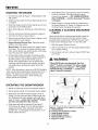
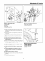
Figure 2. Controls (from operator's position)
A. Speed Selector
B. Traction & Free-Hand TM Control
C. Auger Engage Control
D. Chute Rotator Control
E. Remote Deflector Control
F. Easy Turn Lever
14

Operation
GROUND SPEED SELECTOR
Use the speed selector (A, Figure 2) to control the drive
speed of the snowthrower. There are five forward speeds
and two reverse speeds.
Use the lower speeds to blow deep or wet snow. Use the
higher speeds to blow light snow or to drive the snow-
thrower without blowing snow.
To change speeds, release the auger control lever (B,
Figure 2), then move the speed selector to the desired
setting. Fully depress the control levers to resume.
ENGINE SPEED
Always run the snowthrower at full throttle.
DEFLECTOR
The distance of the discharged snow is mainly controlled
by the position of the deflector. (Engine speed also
affects distance of discharge.) The more the deflector is
tilted UP, the farther snow will be thrown.
1. Push the remote deflector control (C) to the left to
UNLOCK the control. Sliding the contort forward(B)
will put the deflector to the maximum throwing posi-
tion (A). Sliding the control backwards to decrease
the throwing distance.
2. Release the control to LOCK in place when the
desired angle has been chosen.
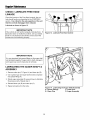
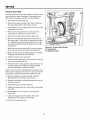
SCRAPER BAR & SKID SHOES
On smooth surfaces such as concrete or asphalt, the
scraper bar (A, Figure 4) should scrape the surface. On
surfaces such as gravel, the scraper bar should be high
enough so that it will not pick up gravel or debris.
The height of the scraper bar (A) is controlled by raising
or lowering the skid shoes (B).
1. To raise the scraper bar height, rest the scraper bar
(A) on a strip of wood equal in thickness to the desired
height.
2. Make sure the scraper bar is parallel to the ground
surface.
3. Loosen the skid shoe nuts (C) and let the skid shoes
(B) drop to the surface.
4. Tighten the nuts (C), making sure the skid shoes are
adjusted equally and are parallel to the surface.
5. To lower the height of the scraper bar, raise the skid
shoes.
6. If the scraper bar becomes worn, it can be replaced
by removing the hardware attaching it to the
snowthrower.
Figure 3. Remote Deflector Control
A. Maximum Throwing Position
B. Spring
®
Figure 4. Skid Shoe Adjustment
A. Scraper Bar
B. Skid Shoe
C. Nuts
15

Operation
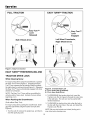
FULL TRACTION
Turn TM
Lever
Released
Both Wheels Drive
i
EASY TURN TM TRACTION
Easy Turn TM
Lever
Engaged
Left Wheel Freewheels,
Right Wheel Drives
Figure 5. Easy Turn Control
EASY TURN TM FREEWHEELING AND
TRACTION DRIVE LOCK
While Clearing Snow:
For easy turning when using the snowthrower, squeeze
the Easy Turn TM lever (Figure 5). Engaging the Easy
Turn TM lever releases the left traction wheel but allows
the right wheel to continue driving (Figure 5). Releasing
the Easy Turn TM lever automatically engages both drive
wheels for full traction.
NOTE: The Easy TurnTM lever will be more difficult to
activate under a heavy load. Activate the lever before
beginning a turn.
When Pushing the Snowthrower:
(Units without Easy Turn)
For easy turning when pushing the snowthrower, disen-
gage the right wheel using the traction lock pin (See
Figure 6.)
1. Turn the unit off, remove the engine key, and discon-
nect the spark plug wire.
Figure 6. Traction Drive Lock
A. Pin in Outer Hole (Freewheel)
B. Pin in Inner Hole (Drive)
2. To DISENGAGE the traction drive lock, insert the
Traction Lock Pin (A, Figure 6) through the outer hole
in the right axle. The unit can now be pushed with
minimal resistance.
3. To ENGAGE the traction drive lock, align the hole in
the hub with the inner hole in the axle, and install the
Traction Lock Pin (B).
NOTE: Be sure both wheels are locked (locking pin in
inner hole) when clearing snow.
16

Operation
AFTER EACH USE
Normal use of the snowthrower may result in a build-up
of packed snow in and around the starter cord housing
and around engine controls. Heat from the engine will
usually prevent the snow from freezing solid while the
unit is running, but after the engine is shut down, some
snow may continue melting from engine heat, and later
freeze around some moving parts as the unit cools.
After each period of use, follow these steps to prevent
freeze-up caused by ice formation in and around the
engine controls and external parts.
1. Before shutting off the engine, pull the starter rope
out 2 - 3 times, and allow it to rewind slowly. This will
help clear packed snow from the starter cord area.
Allow the engine to run for several minutes.
2. Stop the engine by moving the throttle lever (See
Figure 1) down, turn the stop switch to the off position
or by pulling out the engine key.
3. Brush snow and ice from the snowthrower. Be sure to
clear engine and snowthrower controls, discharge
chute, and chute rod gears, clutch cable areas, and
anywhere else snow has accumulated.
4. Always remove the engine key and store in a safe
place to prevent unauthorized use.
WARNING
Never store the unit (with fuel) in an enclosed,
poorly ventilated structure. Fuel vapors can
travel to an ignition source (such as a furnace,
water heater, etc.) and cause an explosion.
Fuel vapor is also toxic to humans and animals.
5. If the snowthrower is kept in a cold shelter, fill the fuel
tank to prevent condensation. Do not store near
sparks or flame.
Note: The Engine Owner's Manual contains further infor-
mation on preventing ice formation and freeze-up.
WARNING
Never store the unit, with gasoline in engine or
fuel tank, in a heated shelter or in enclosed,
poorly ventilated enclosures. Gasoline fumes may
reach an open flame, spark or pilot light (such as
a furnace, water heater, clothes dryer, etc.) and
cause an explosion.
Handle gasoline carefully. It is highly flammable
and careless use could result in serious fire
damage to your person or property.
Drain fuel into an approved container outdoors
away from open flame or sparks.
STORAGE
WARNING
Never store the unit (with fuel) in an enclosed,
poorly ventilated structure. Fuel vapors can
travel to an ignition source (such as a furnace,
water heater, etc.) and cause an explosion.
Fuel vapor is also toxic to humans and animals.
Before you store your unit for the off-season, read the
Maintenance and Storage instructions in the Safety
Rules section, then perform the following steps:
• Disengage the PTO, set the parking brake, and
remove the key.
• Perform engine maintenance and storage measures
listed in the engine owner's manual. This includes
draining the fuel system, or adding stabilizer to the
fuel (do not store a fueled unit in an enclosed struc-
ture - see warning).
Before starting the unit after it has been stored:
• Check all fluid levels. Check all maintenance items.
• Perform all recommended checks and procedures
found in the engine owner's manual.
• Allow the engine to warm up for several minutes
before use.
17

RegularMaintenance
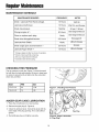
MAINTENANCE SCHEDULE
MAINTENANCE REQUIRED FREQUENCY NOTES
Check / Lubricate Free-Hand Linkage.
Lubricate snowthrower.
Check tire pressure.
Change engine oil.*+
Clean or replace spark plug.+
Check drive linkage/belt tension.
Lubricate Axle Shafts.
Check auger gear case lubrication.**
Lubricate Auger Shaft.***
* Change original oil after two hours of operation.
** Check oil level each fall and spring.
+ See your engine Owner's Manual.
***Lubricate each fall and spring.
10 Hours 10W Oil
10 Hours 10W Oil and Grease
Monthly 20 psi (1.38 bar)
50 Hours; See Engine Manual
Yearly See Engine Manual
4-6 Hours See page 24
Yearly Lithium Grease
25 Hours Grease
10 Hours Lithium Grease
CHECKING TIRE PRESSURE
The air pressure in each tire (Figure 7) should be equal
for both tires for best performance. Be sure to keep caps
on valves to prevent entry of debris into the valve stem
when tires are filled.
Size PSI bar
15 x 5.0-6 20 1,38
16 x 4.8-8 14 ,96
AUGER GEAR CASE LUBRICATION
1. Place the snowthrower on a level surface.
2. Remove the pipe plug (A, Figure 8).
3. Check the lubricant level. It should be level with the
lower edge of the plug opening. If not, add Lithium
grease.
4. Re-install pipe plug, and tighten securely.
Figure 7. Checking Tire Pressure
Pipe Plug
Figure 8. Auger Lubrication
A. Pipe Plug
18

Regular Maintenance
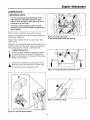
LUBRICATION
IMPORTANT NOTE
It is very important that grease fittings on the
auger shaft are lubricated regularly. If auger
rusts to shaft, damage to worm gear may occur
if shear pins do not break.
To prevent wheels rusting to axles, it is also
necessary to remove the wheels and grease the
axles regularly.
Remove wheels and grease axles once each year.
Apply 5W-30 synthetic motor oil to the friction disk drive
hex shaft (A, Figure 10).
Apply medium weight (10W) oil to points shown (See
Figures 9-12).
Generally, all moving metal parts should be oiled where
contact is made with other parts. Keep oil and grease off
belts, pulley grooves, drive disc, and friction disc.
LUBRICATION NOTES:
Grease locations indicated by grease gun symbol.
Use grease fittings when present. Disassemble
parts to apply grease to moving parts when grease
fittings are not installed.
Figure 10. Drive Lubrication
A. Hex Shaft (Behind Rod with Spring)
Oil locations indicated by oil can symbol. Do not
allow oil to drip onto traction drive or friction disc.
Do not lubricate remote deflector control.
Figure 11. Lubricate Axles and Control Levers
Figure 12. Deflector Hinge
Figure 9. Lubricate Spout Rotator
19
Page is loading ...
Page is loading ...
Page is loading ...
Page is loading ...
Page is loading ...
Page is loading ...
Page is loading ...
Page is loading ...
Page is loading ...
Page is loading ...
Page is loading ...
Page is loading ...
Page is loading ...
Page is loading ...
-
 1
1
-
 2
2
-
 3
3
-
 4
4
-
 5
5
-
 6
6
-
 7
7
-
 8
8
-
 9
9
-
 10
10
-
 11
11
-
 12
12
-
 13
13
-
 14
14
-
 15
15
-
 16
16
-
 17
17
-
 18
18
-
 19
19
-
 20
20
-
 21
21
-
 22
22
-
 23
23
-
 24
24
-
 25
25
-
 26
26
-
 27
27
-
 28
28
-
 29
29
-
 30
30
-
 31
31
-
 32
32
-
 33
33
-
 34
34


Simplicity 95288E (1694994) Owner's manual
- Category
- Snow throwers
- Type
- Owner's manual
Ask a question and I''ll find the answer in the document
Finding information in a document is now easier with AI
Related papers
-
Simplicity 1691411 User manual
-
-
-
-
Snapper 520E User manual
-
Simplicity 1694242 User manual
-
-
-
-
Other documents
-
-
Bolens 31AE9P3J565 Owner's manual
-
 Craftex CT103N Owner's manual
-
-
Snapper 10528 User manual
-
-
Snapper I8245E Owner's manual
-
-
-
