Page is loading ...

APPROVED
Z21.60b
-
2004 /
CSA 2.26b
-
2004
S
P
A
R
K M
O
D
E
R
N F
I
R
E
S
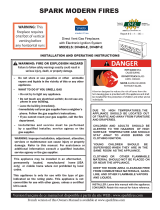
RETROFIT FIRE RIBBON
VENTED DECORATIVE APPLIANCE
-
Installation and service must be performed
by a qualified installer, service agency, or
the gas supplier.
-
Do not store or use gasoline or other
flammable vapors and liquids in the vicinity
of this or any other appliance.
-
WHA
T TO DO IF YOU SMELL GAS:
Do not try to light any appliance.
Do not touch any electrical switch; do not
use any phone in your building
.
Immediately call your gas supplier
from a
neighbor’s phone. Follow the gas
supplier’s instructions.
If you cannot reach
your gas supplier, call
the fire department.
WARNING: If the information in this
manual is not followed exactly, a fire
or explosion may result causing
property damage, personal inju
ry, or
loss of life.
WARNING: Improper installation, adjustment,
alteration, service, or maintenance can cause injury
or
property damage. Refer to this manual for
correct installation and operational procedures. For
assistance or additional information consult a
qualified installer, service agency, or gas supplier.
WARNING: This appliance is for
install
ation only in
a solid-fuel burning masonry or UL127 factory-
built
fireplace, constructed of noncombustible material,
and connected to a working flue (see page 4
for
minimum flue opening)
.
WARNING: This is a gas-
fired appliance. It uses air
(oxyge
n) from the room in which it is installed.
Provisions for adequate combustion and ventila-
tion
air must be provided.
INSTALLER:
Leave this manual with the appliance.
CONSUMER:Retain t
his manual for future reference
(IPS)
OWNER’S OPERATION AND INSTALLATION MANUAL
NOTE: This appliance is not approved for installation in bedrooms or bathrooms.
5HSRUW/E
9HUVLRQIUDQoDLVHGHFHPDQXHOHVWGLVSRQLEOHjSDUWLUGXVLWH:(%ZZZVSDUNILUHVFRP
)UHQFKYHUVLRQRIWKLV2ZQHUV0DQXDOLVDYDLODEOHDWZZZVSDUNILUHVFRP

2
SAFETY
I
NFORMATION
Carbon Monoxide Poisoning:
Earl
y signs of carbon monoxide
poisoning resemble the flu, with
headaches, dizziness, or nausea. If
you have these signs, the fire
Ribbon may not be working
properly. Get fresh air at once!
Have Fire Ribbon serviced. Some
people are more affected by
carbon monoxide than others.
These include pregnant women,
people with heart or lung disease
or anemia, those under the
influence of alcohol, and those at
high altitudes.
Natural and Propane /LP Gas:
Natural and propane /LP gases are
odorless. An odor making agent is
added to the gas. The odor helps
you detect a gas leak. However,
the odor added to the gas can fade.
Gas may be present even though
no odor exists.
Make certain you read and under-
stand all warnings. Keep this
manual for reference. It is your
guide to safe and proper operation
of this Fire Ribbon.
1. This appliance, as supplied, is
only for use with the type of
gas indicated on the rating
plate.
2. If you smell gas:
• shut off gas supply
• do not try to light any appli-
ance
• do not touch any electrical
switch; do not use any phone
in your building
• immediately call to your gas
supplier from a neighbor’s
phone. Follow the gas
supplier’s instructions
• if you cannot reach your gas
supplier, call the fire depart-
ment
3. Never install the Fire Ribbon:
• in a recreational vehicle
• where curtains, furniture,
clothing, or other flammable
objects are less than 42 inches
from the front, top, or sides of
the Fire Ribbon
• in the high traffic areas
• in windy or drafty areas
4. Before installing in a solid
fuel burning fireplace, the
chimney flue and firebox
must be cleaned of soot,
creosote, ashes and loose
paint by a qualified chimney
cleaner. Creosote will ignite if
highly heated. Inspect chim-
ney flue for damage.
5. Fire Ribbon is designed to be
smokeless. If it ever appears
to smoke, turn off appliance
and call a qualified service
person. NOTE: During initial
operation, slight smoking
could occur due to unit curing
and the burning of
manufacturing residues.
6. To reduce the creation of soot,
follow the instructions in
Cleaning and Maintenance,
page 9.
7. Do not allow fans to blow
directly into the fireplace.
Avoid any drafts that alter
burner flame patterns, as it
could increase soothing.
8. Do not use a blower insert,
heat exchanger insert or other
accessory not approved for
use with this Fire Ribbon.
9. This Fire Ribbon needs fresh,
outside air ventilation to run
properly.
10. Keep the appliance area clear
and free from combustible
materials, gasoline and other
flammable vapors and liquids.
11. Do not burn solid fuel in the
fireplace after installing the
Fire Ribbon. Do not use this
appliance to cook food or
burn paper or other objects.
12. Fire Ribbon becomes hot
when in use. Keep children
and adults away from hot
surface to avoid burns or
clothing ignition. Fire Ribbon
will remain hot for a time
after shut-down. Allow
surface to cool before
touching.
13. Carefully supervise young
children when they are in the
room with Fire Ribbon.
14. Do not use appliance if any
part has been exposed to or
under water. Immediately call
a qualified service technician
to inspect the room appliance
and to replace any part of the
WARNING:
Any change
to this Fire Ribbon or its
controls can be dangerous.
WARNING: Keep flue
open when operating unit.
IMPORTANT: Read this
owner’s manual carefully
and completely before trying
to assemble, operate, or
service this Fire Ribbon.
Improper use of this unit can
cause serious injury or
death from burns, fire,
explosion, electrical shock,
and carbon monoxide
poisoning.
DANGER: Carbon mo-
noxide poisoning may lead
to death!
IMPORTANT: Fireplace
doors must be open when
appliance is operating.

3
control system and any gas
control which has been under
water.
15. Turn the Ribbon off and let
cool before servicing,
installing, or repairing. Only a
qualified service person
should install, service, or
repair Fire Ribbon.
LOCAL CODES
I
n
s
t
a
ll and use Fire Ribbon with
care. Follow local codes. In the
absence of local codes, use the
latest edition of The National Fuel
Gas Code ANSZ223.1, also
known as NFPA 54 available
from:
• American National Standards
Institute, Inc., 1430
Broadway, New York,
NY 10018
• National Fire Protection
Association, Inc.,
Batterymarch Park, Quincy,
MA 02269.
PRODUCT ASSEMBLY
1. Rem
ove Burner Assembly,
Front Cover, Access Panel
and Burner Media from
packaging (see Parts List,
page 14).
2. Connect the Burner Assembly
to gas supply using supplied
flex connector and shutoff
valve.
3. Evenly fill the media
compartment with burner
media (broken tempered
glass) fully covering the
burner as shown on a picture.
If you are NOT planning to
add optional topping media,
then fill the media
compartment in full and
proceed to the step 5.
NOTE: If you are planning to
add some topping media
(optional colored glass or lava
rock), leave approximately ¾”
not filled on top of burner
media and proceed to the next
step.
4. Place and evenly distribute
topping media (optional
colored glass or lava rock) on
top of burner media as shown
in picture.
Make sure that pilot opening
is
not
blocked
with
media.
5
.
Carefully leak test all
connections following the
procedure on page 5.
6. Having free access to the
valve and manifold
compartment of the Burner
Assembly turn ON the
appliance following the
procedure on page 7.
Make sure the flame is even
along the burner and
appliance is fully operational
and safe for use. Turn OFF
the appliance and let it cool
before proceeding to the next
step.
7. Cover manifold and valve
compartment of the Burner
Assembly with Front Cover
making sure that access
window is located above the
valve
as
shown
in picture.
Cover the window with
Access
Panel
as
shown
in pic-
t
u
r
e
.
WARNING: Failure to position
the parts in accordance with
these diagrams or failure to
use only parts specially
approved with this appliance
may result in property
damage or personal injury.

4
INSTALLATION
NOTE:
This vented appliance
must be installed only in a solid-
fuel
burning fireplace with a
working flue and constructed of
noncombustible material. The
installation of appliances designed
for manufactured home (U.S.
only) or mobile home installation
must conform with the Standard
CAN/CSA Z240 MH
,
Mobile
Housing,
in Canada, or with the
Manufactured Home Construction
and Safety Standard, Title 24 CFR,
Part 3280
, in the USA, or when
such a standard is not applicable,
ANSI/NCSBCS A225.1/NFPA 501A,
Manufactured Home Installations
Standard.
The fireplace must include a
working flue and venting system
with minimum opening.
Please,
make sure that the following
technical data related to proper
installation of the F
ire
Ribbon
are
applicable before
install
ation is
attempted
.
VENTING
SPECIFICATIONS FOR
INSTALLATION
The fireplace chimney flue and
vent must be drafting properly. To
check the vent for proper drafting:
Light a tightly rolled newspaper
on the end and place it at the
inside front edge of the fireplace.
Observe the smoke and be sure
the vent is properly drawing it up
the chimney. If the smoke spills
out into the room, extinguish the
flame and remove any obstruction
until proper venting is achieved.
The chimney flue must remain
open a minimum of 3” at all times
during
the operation of this F
ire
Ribbon
.
INSTALLING DAMPER
CLAMP
Secure the damper stop clamp
provided to the leading edge of
the damper as shown
below
. If for
any reason this clamp doesn’t
work on your fireplace, another
suitable clamp or permanent stop
must be installed, or the damper
blade must be cut or removed.
CAUTION: Do not remove
the metal data plates
attached to the F
ire
Ribbon
.
These plates contain
important information.
NOTICE:
Installation, ser-
vice, and repair of this ap-
pliance must be performed
by a
qualified
install
er,
service agency, company or
gas supplier experienced
with this type of gas
appliances. Only factory
authorized components lis-
ted in this
instructi
on may
be u
sed in accordance with
the manufacturer’s
instruct
-
tions and all codes and
requirements of the autho-
rity having jurisdiction. Any
modifications to this
appli
-
ance
or use of unauthorized
components or accessory
items will void the manu-
facturer’s warranty,
and may
result in a hazardous
condition.
WARNING: Before
install
-
ling in a solid fuel burning
fireplace, the chimney flue
and firebox must be cleaned
of soot, creosote, ashes
and
loose paint by a qualified
chimney cleaner. Creosote
will ignite if highl
y heated. A
dirty chimney flue may
create and distribute soot
within the house. Inspect
chimney flue for damage.
Minimum firebox size:
-
Height
18”
-
Depth
14”
-
Width
/Model:
RETRO
-2 ……..…..28”
RETRO
-3 ……..…..40”
RETRO
-4 ……..…..52”
RETRO
-5 ……..…..64”
RETRO
-8 ……..…100”
Fuel Pressure Specification:
-
Inlet (NG)
4.5.-10.5”w.c.
-
Manifold (NG) 3.5”w.c.
-
Inlet (LP)
11-13”w.c.
- Manifold (LP) 10”w.c.
RETRO
-6 ……..…..7
6”
RETRO
-7 ……..…..8
8”

24 L100001
25
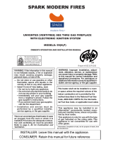
Figure 32 - External Regulator with Vent Pointing Down
(Propane/LP Only)
FIREPLACE INSTALLATION
CHECK GAS TYPE
Use proper gas type for the replace you are installing. If you have conicting gas type, do not install replace. See dealer where
you purchased the replace for proper replace for your gas type or conversion kit.
INSTALLING GAS PIPING TO FIREPLACE / BURNER SYSTEM LOCATION
INSTALLATION ITEMS NEEDED
Before installing replace and burner system, make sure you have the items listed below.
• External regulator (supplied by installer) • Piping (check local codes) • Sealant (resistant to propane/LP gas)
• Equipment shutoff valve* • Test gauge connection* • Sediment trap (recommended)
• Tee joint • Pipe wrench
• approved exible gas line with gas connector (if allowed by local codes — not provided)
* A CSA design-certied equipment shutoff valve with
1
/8" NPT tap is an acceptable alternative to test gauge connection.
Purchase the CSA design-certied equipment shutoff valve from your dealer.
For propane/LP connections only, the installer must supply an external regulator. The external regulator will reduce incoming
gas pressure. You must reduce incoming gas pressure to between 11 and 13 inches of water. If you do not reduce incoming gas
pressure, burner system regulator damage could occur. Install external regulator with the vent pointing down as shown in Figure
32. Pointing the vent down protects it from freezing rain or sleet.
External
Regulator
100 lb. (min)
Propane/LP
Supply Tank
Vent Pointing
Down
When using copper or ex connectors use only ttings approved
for gas connections. The gas control inlet is
3
/8" NPT.
A qualified installer or service person must
connect appliance to gas supply. Follow all
local codes.
WARNING
For propane/LP units, never connect fireplace directly to the propane/LP supply. This
burner system requires an external regulator (not supplied). Install the external regulator
between the burner system and propane/LP supply.
CAUTION
Use only new black iron or steel pipe. Internally
tinned copper or copper tubing can be used per
National Fuel Code, section 2.6.3, providing gas
meets hydrogen sulfide limits, and where permitted
by local codes. Gas piping system must be sized
to provide minimum inlet pressure (listed on data
plate) at the maximum flow rate (BTU/hr). Undue
pressure loss will occur if the pipe is too small.
CAUTION

26
L100001 27
FIREPLACE INSTALLATION
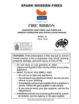
A listed manual shutoff valve must be installed upstream of the appliance. Union tee and plugged
1
/8" NPT pressure tapping
point should be installed upstream of the appliance. See Figure 33.
IMPORTANT: Install main gas valve (equipment shutoff valve) in an accessible location. The main gas valve is for
turning on or shutting off the gas to the fireplace.
Check your building codes for any special requirements for locat-
ing equipment shutoff valve to replaces.
Apply pipe joint sealant lightly to male threads. This will prevent
excess sealant from going into pipe. Excess sealant in pipe could
result in clogged burner system valves.
We recommend that you install a sediment trap/drip leg in supply
line as shown in Figure 33. Locate sediment trap/drip leg where it is within reach for cleaning. Install in piping system between
fuel supply and burner system. Locate sediment trap/drip leg where trapped matter is not likely to freeze. A sediment trap traps
moisture and contaminants. This keeps them from going into the burner system gas controls. If sediment trap/drip leg is not
installed or is installed wrong, burner system may not run properly.
Figure 33 - Gas Connection
Tee Joint
Pipe Nipple
Cap
Approved Flexible Gas
Line
CSA Design-Certied Equipment Shutoff Valve
with
1
/8" NPT Tap*
Sediment Trap/Drip Leg
Natural Gas
From Gas Meter
(5" W.C. to 10.5" W.C. Pressure)
Propane/LP
From External Regulator
(11" W.C. to 13" W.C. Pressure)
NOTE : The gas line connection may be made using
1
/2" rigid tubing or an approved ex connector. Since some
municipalities have additional local codes it is always best to consult your local authorities and the current edition
of the National Fuel Gas Code ANSI.Z223.1, NFPA54. In Canada CAN/CGA-B149 (1 or 2) Installation Code.
Only persons licensed to work with gas piping
may make the necessary gas connections to
this appliance.
WARNING
A manual shutoff valve must be installed upstream
of the appliance. Union tee and plugged
1
/8"
NPT pressure tapping point should be installed
upstream of the appliance. See Figure 33.
CAUTION
Use pipe joint sealant that is resistant to liquid
petroleum (LP) gas.
CAUTION

7
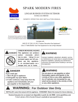
MEDIA BURNER TRAY
PILOT
FIRE RIBBON RETROFIT BURNER
MODEL SPECIFICATIONS
CONTROL ACCESS PANEL
BURNER TUBE
OVERALL
INPUT RATE (BTU/Hr)
61,000
54,000
72,000
90,000
82,000
129,000
116,000
102,000
142,000
128,000
110,000
146,500
41,000
33,500
4 ( 1)
8 ( 2)
6 ( 2)
7 ( 2)
3 (1)
43 38
43 46
44 49
44 43
MODEL #
RETRO 2 - NG/LP
RETRO 3 - NG/LP
RETRO 4 - NG/LP
RETRO 5 - NG/LP
RETRO 6 - NG/LP
RETRO 7 - NG/LP
RETRO 8 - NG/LP
N.G. L.P.
# ORIF.
ORIF. SIZE
N.G. L.P.
LENGTH (L)
FIREPLACE
WIDTH (min)
28"
40"
52"
64"
76"
100"
Minimum fireplace depth required = 14” Minimum fireplace height required = 18”
(L)
see chart below
N.G. (L.P.)
43 41
43 38
43 35
88
"
10.125"
4
"
24.125"
36.125"
48.125"
60.125"
72.125"
84.125"
96.125"
5 ( 2)
2 (1)
TOP VIEW
OVERALL HEIGHT = 6"
1.75"
4.25"
1
.25"
adapter which is required to operate Remote Control. However, during power outage situation, its electronic
system (DFC board) can be temporarily powered with 6V DC battery pack (4 AA batteries).
This fireplace requires 110V
AC electrical supply for normal operation in order to power up
7V DC

32 L100001
8
A.This appliance is equipped with an ignition device which automatically lights the pilot. Do not try to light
the pilot by hand.
B. BEFORE OPERATING smell all around the appliance area for gas. Be sure to smell next to the oor because
some gas is heavier than air and will settle on the oor.
WHAT TO DO IF YOU SMELL GAS:
• Do not try to light any appliance.
• Do not touch any electric switch; do not use any phone in your building.
• Immediately call your gas supplier from a neighbor's phone.
Follow the gas supplier's instructions.
• If you cannot reach your gas supplier, call the fire department.
C. Main gas valve in this appliance is not serviceable and does not have any control knobs or switches to operate.
Do not remove heat shields covering the valve and electronic devices; do not try to repair or modify the valve
as it may result in a fire or explosion. Call a qualified service technician if you have any safety concerns.
D. Do not use this appliance if any part of it has been under water. Immediately call a qualied service technician
to inspect the appliance and to replace any part of the control system and any gas control that has been under
water.
LIGHTING INSTRUCTION
FOR YOUR SAFETY READ BEFORE OPERATING
LIGHTING FOR THE FIRST TIME
INITIAL LIGHTING
Purge air from the supply line as follows:
• Open main shutoff valve.
• Unscrew main pressure test point.
• Leave inlet test screw open until gas comes in.
• When gas is owing, tighten inlet screw immediately.
LEAK TESTING
1. Follow the pipe from the gas supply line connection to the gas valve. Check connection for leaks with soap
and water mixture.
2. Next check for gas leaks at the burner with soap and water mixture.
3. Check the pilot for gas leaks with soap and water mixture.
If you do not follow these instruction exactly,
a fire or explosion may result causing property
damage, personal injury or loss of life.
WARNING
Never use an open flame to check for gas leak.
DANGER

L100001 35
Continued
APPROVED LEAK TESTING METHOD
You may check for gas leaks with the following methods only:
• Soap and water solution
• An approved leak testing spray
• Electronic sniffer
NOTE: Remove any excessive pipe compound from
the connections. Excessive pipe compound can set
off electronic sniffers.
OPERATING INSTRUCTIONS
Check for gas leaks in each of the following locations:
• Pipe from the gas supply line connection to the gas valve
• Burner connections, pilot • Field made joints / gas shutoff valve
• All joints on valve and control body • Factory made joints, each joint and connection
WA
If using a soap and water solution to test
for leaks, DO NOT spray solution onto
electronic parts.
WARNING
Never use an open flame to check for gas leak.
DANGER
1. STOP! Read the safety information on previous page.
2. Turn off all electric power to the appliance.
3. Do not attempt to light the pilot by hand.
If you don't smell gas, go to the next step.
WARNING
9
7. Turn the gas control manual valve to the ON position.
8. Plug supplied 7V DC adapter into 110V power outlet.
LIGHTING FOR THE FIRST TIME
4. Remove Front Tray from the appliance (see Illustrated Parts List, page 1).
5. Turn the gas control manual valve to the full OFF position.
6. Wait five (5) minutes to clear out any gas. Then smell for gas, including near the floor.
If you smell gas, STOP! Follow "B" in the safety information (see page n).
9. Connect the wire to the DC input plug at the unit.
11. Locate Remote Receiver inside of the unit
(see Illustrated Parts List, page 14). Make sure that the slider switch
13. Read and follow instructions in how to set up and to use remote control described in supplied
14. If the appliance will not operate, follow the instructions "To Turn Off Gas To Appliance" and call
your service technician or gas supplier.
of the Receiver is in "REMOTE"
(middle) position.
10. Lift and remove Heat Shield covering electronic components inside of the unit
(see Illustrated Parts List, page 1
).
12. Replace Heat Shield and then replace Front Tray.
"Use and Installation Instructions for
REMOTE CONTROL SYSTEM".

34 L100001
10
Continued
T
TO TURN OFF GAS TO APPLIANCE
Unplug 7V DC adapter from the power outlet.
3. Turn the gas control manual valve to the full OFF position.
1. Turn off all electric power to the appliance if service is to be
performed.
2. If necessary, remove Front Tray from the appliance to access
manual shutoff valve on gas line.
4. If necessary, replace Front Tray.
ELECTRICAL WIRING
WARNING
Label all wires before disconnecting when
servicing controls. Wiring errors can cause
improper and dangerous operation.
CAUTION
Electrical connections should only be performed by a qualified, licensed electrician.
Main power must be off when connecting to main electrical power supply or performing
service. All wiring shall be in compliance with all local, city, and state codes. The
appliance, when installed, must be electrically grounded in accordance with local
codes, or in the absence of local codes, with the National Electrical Code ANSI/ NFPA
70 (latest edition) and Canadian Electrical Code, CSA C22.1.
adapter which is required to operate Remote Control. However, during power outage situation, its electronic
system (DFC board) can be temporarily powered with 6V DC battery pack (4 AA batteries).
This fireplace requires 110V
AC electrical supply for normal operation in order to power up
7V DC
WARNING
within the appliance.
Do not operate the appliance without the burner being completely filled with glass media.
Lighting the burner without the glass media will cause unsafe temperatures

CLEANING AND MAINTENANCE
BURNER, PILOT AND CONTROL COMPARTMENT
Keep the control compartment clean by vacuuming or brushing at least twice a year.
Make sure the burner porting, pilot air opening and burner air opening are free of obstructions at all times.
PILOT FLAME
The ames from the pilot should be visually checked as soon as the unit is installed
and periodically during normal operation. The pilot flame must always be present
when the fireplace is in operation or connected to the gas line with main shutoff
valve open and the IPS activated (powered). The pilot flame has two distinct
BURNER
Inspect area around the burner. Remove any lint or foreign material with a brush
or vacuum.
Turn off gas before servicing fireplace. It
is recommended that a qualified service
technician perform these check-ups at the
beginning of each heating season.
WARNING
Have the venting system of the solid fuel burning fireplace inspected and cleaned
annually by a qualified agency.
1
flames, one engulfing the flame sensor and the other reaching to the main burner.
Pilot Flame
11
VENTING SYSTEM
ELECTRICAL WIRING
WARNING
Label all wires before disconnecting when
servicing controls. Wiring errors can cause
improper and dangerous operation.
CAUTION
Electrical connections should only be performed by a qualified, licensed electrician.
Main power must be off when connecting to main electrical power supply or performing
service. All wiring shall be in compliance with all local, city, and state codes. The
appliance, when installed, must be electrically grounded in accordance with local
codes, or in the absence of local codes, with the National Electrical Code ANSI/ NFPA
70 (latest edition) and Canadian Electrical Code, CSA C22.1.
adapter which is required to operate Remote Control. However, during power outage situation, its electronic
system (DFC board) can be temporarily powered with 6V DC battery pack (4 AA batteries).
This fireplace requires 110V
AC electrical supply for normal operation in order to power up
7V DC

TROUBLESHOOTING
WARNING: Turn off the unit
and let cool before servicing. Only
a qualified service person should
service and repair this appliance.
OBSERVED PROBLEM POSSIBLE CAUSEREMEDY
OBSERVED PROBLEM
1. Poor fuel quality
2. Fireplace venting system not drafting
properly
3. Excessive flame impingement or block-
age
4. Improper fuel/air mixture
1. Passage of air/gas across irregular sur-
faces
2. Excessive gas pressure on natural gas
units
1. Incorrect gas supply or pressure
2. Blocked burner orifice or burner mani-
fold ports
3. Improper burner orifice size
1. Battery is not installed. Battery power
is low
Unit is smoking / sooting excessively
(
Note:
It is natural and unavoidable for
appliance sets to produce moderate
levels of carbon (soot) where flames
contact the media. This is especially
true with propane/LP gas.)
Burner is excessively noisy
(
Note:
The movement and combustion of
gas will create low, unavoidable levels of
noise.)
Burner flame is too low or too high
Remote does not function
1. Contact local natural or propane/LP gas
company
2. Adjust damper wide open and/or have
fireplace and venting professionally
cleaned and checked
3.Separate the stones to allow more flame
passage
4. Remove any foreign items from the
flame pattern and/or check for proper
orifice sizing
1. Relieve any tight bends or kinks in gas
supply line
2.Check/reset gas regulator pressure
1. Check for proper gas supply pressure
2. Free burner orifice and manifold ports
of any burrs, paint, or other blockage
3. Verify proper burner orifice sizing (see
page 7)
1.Replace batteries in receiver and
Note:
All troubleshooting items are listed in
order of operation.
12
5. Not enough media over burner tube.
5. Make sure burner tube is completely covered
with glass media.
remote control. Re-program the receiver.
i.e. spider webs, etc.

OBSERVED PROBLEM
Burner does not light after pilot is lit
Delayed ignition burner
Unit produces unwanted odors
Gas odor even when Remote Control is
REMEDY
1.Turn on gas supply or open manual
2.Purge air from the supply line
(see page )
3.Adjust pilot flame for approximately
1" blue flame
4.Clean pilot (see Cleaning and Mainte-
nance, page 1) or replace pilot assembly.
1.Clean burner orifice
2.Contact local natural or propane/LP gas
1.Adjust pilot flame for approximately
1" blue flame
1. Open flue to maximum. Stop using odor
causing products while unit is running
carpet, etc. (See statement above).
2. Locate and correct all leaks (see Check-
ing Gas Connections, page 5)
1.Locate and correct all leaks (see p.5)
in OFF position
Continued
POSSIBLE CAUSE
1.Gas supply turned off or manual shutoff
valve closed shutoff valve
2.Air in gas lines when installed
3.Pilot adjustment screw closed
4.Pilot is clogged
5.Ignitor electrode broken
1.Burner orifice clogged
2.Inlet gas pressure is too low
3.Burner orifice diameter is too small
1.Pilot flame needs adjusting
1. Unit burning vapors from paint, hair
spray, glues, cleaners, chemicals, new
2. Gas leak. See Warning statement above.
1.Gas leak. See Warning statement above.
IMPORTANT:
Operating unit where impurities in air exist may create odors.
Cleaning supplies, paint, paint remover, cigarette smoke, cements and glues, new
carpet or textiles, etc., create fumes. These fumes may mix with combustion air
and create odors. These odors will disappear over time.
13
WARNING: If you smell gas
• Shut off gas supply.
• Do not try to light any appliance.
• Do not touch any electrical switch; do not use any phone in
your building.
• Immediately call your gas supplier from a neighbor’s phone.
Follow the gas supplier’s instructions.
• If you cannot reach your gas supplier, call the fire department.
1. Gas leak. See Warning statement at
top of page
position
Gas odor during combustion 1. Locate and correct all leaks (see Check-
ing Gas Connections, page 5)
13
When remote control / switch is pressed,
there is spark at pilot but no ignition
5.
Replace pilot assembly.
company to check pressures and
gas pipe sizing.
3. Replace burner orifice(s).
4.Flame sensor leads disconnected.
5. DFC Module failure.
4.Reconnect leads.
5. Replace DFC module.
2. Main gas valve defective 2. Replace gas valve.

ILLUSTRATED PARTS LIST
SEE NEXT PAGE
FOR PART DESCRIPTION
ILLUSTRATED PARTS LIST
SEE NEXT PAGE
FOR PART DESCRIPTION
ILLUSTRATED PARTS LIST
1
2
SEE NEXT PAGE
FOR PART DESCRIPTION
2
3
4
5
7
8
9
9
10
11
12
13
14
15
1818
19

PARTS LIST
This list contains replaceable parts used in your RETROFIT
–
IPS appliance
Part Number
a
ccording to the Fire Ribbon Model
for Natural Gas (and LP
)
Key
#
Part Description
RETRO
FIT
-
2’
RETROFIT
-3’
RETROFIT
-4’
RETROFIT
-5’
RETROFI
T-6’
RETROFIT
-7’
RETROFIT
-8’
Q-
ty
1
Burner Assembly
W110
1
02P
W110
1
03P
W110
1
04P
W110
1
05P
W110
1
06P
W110
1
07P
W110
1
08P
1
(
W120
1
02P
) (
W120
1
03P
) (
W120
1
04P
) (
W120
1
05P
) (
W120
1
06P
) (
W120
1
07P
) (
W120
1
08P
)
2
Main Gas Valve
R10002
6
R10002
6
R1000
26
R10002
6
R10002
6
R10002
6
R10002
6 1
(R
1
0002
7)
(R
1
0002
7)
(R
1
0002
7)
(R
1
0002
7)
(R
1
0002
7)
(R
1
0002
7)
(R
1
0002
7)
3
Pilot Assembly
R10002
8
R10002
8
R10002
8
R10002
8
R10002
8
R10002
8
R10002
8 1
(R
1
0002
9)
(R
1
0002
9)
(R
1
0002
9)
(R
1
0002
9)
(R
1
0002
9)
(R
1
0002
9)
(R
1
0002
9)
5 DFC
Wire Assembly
H100
1
41
H100
1
41
H100
1
41
H100
141
H100
1
41
H100
1
41
H100
1
41
1
6
Valve Bracket
(NOT SHOWN)
D400
1
60P
D400
1
60P
D400
1
60P
D400
1
60P
D400
1
60P
D400
1
60P
D400
1
60P
1
7
Valve Shield
D400
1
61P
D400
1
61P
D400
1
61P
D400
1
61P
D400
1
61P
D400
1
61P
D400
1
61P
1
Continued on Ne
xt Page
4
Burner Flex Connector
C100010
C100010
D300098 D300098 D300098 D300098 D300098 1
(C1000
10)
(C100010)
(D300098)
(D300098)
(D300098)
(D300098)
(D300098)

PARTS LIST
(CONTINUED)
This list contains replaceable parts used in your RETROFIT
–
IPS appliance
Part Number according to the Fire Ribbon Model for Natural Gas (and LP)
Key
#
Part Description
RETROFIT
-
2’
RETROFIT
-3’
RETROFIT
-4’
RETROFI
T-5’
RETROFIT
-6’
RETROFIT
-7’
RETROFIT
-8’
Q-
ty
8
Manifold complete
with Tubing Assembly
W130002P
W130003P
W130004P
W130005P
W130006P
W130007P
W130008P
1
9
Orifice
R100044
2
(Air Mixer for LP)
(R2000
61
)
R100044
3
(R2000
62
)
R100043
4
(R2000
63
)
R100043
5
(R2000
64
)
R100043
6
R100043
R100043
8
10
Front Tray
D400034P
D40005
4P
D400053P
D400009P
D400017P
D400024P
D400010P
1
Continued on Next Page
1
1
1
2
2
7
2
2
(R2000
66
)
(R2000
63
)
(R2000
67
)

PARTS LIST
(CONTINUED)
This list contains replaceable parts used in your RETROFIT
–
IPS appliance
Part Number according to the Fire Ribbon Model for Natural Gas (and LP)
Key
#
Part Description
RETROFIT
-
2’
RETROFIT
-3’
RETROFIT
-4’
RETROFIT
-5’
RETROFIT
-6’
RETROFIT
-7’
RETROFIT
-8’
Q-
ty
11
Access Panel
D400058P
D400058P
D400058P D400058P D400058P D400058P D400058P
1
12
DFC Board
H100
1
42
H100
142
H100
1
42
H100
1
42
H100
1
42
H100
1
42
H100
1
42
1
15
7V 10m
A DC adapter
H100
1
40
H100
1
40
H100
1
40
H100
1
40
H100
1
40
H100
1
40
H100
1
40
1
16
Damper Clamp
(
NOT SHOWN
)
F100037
P
F100037
P
F100037
P
F100037
P
F100037
P
F100037
P
F100037
P 1
17
Glass Burner Media
(
NOT SHOWN
)
G100030
G100030
G100030
G100030
G100030
G100030
G100030
Pkg
18
Top Media
(
MANY
TYPES AVAILABLE
)
19
Heat Shield
D400165P
D400165P
D400165P
D400165P
D400165P
D400165P
D400165P
1
NOTE: Specifications, finishes and dimensions are subject to change!
xxx xxx xxx xxx xxx xxx xxx
Pkg
13
Remote
Receiver
RCB-R RCB-R RCB-R RCB-R RCB-R RCB-R RCB-R 1
ON/OFF
Remote Control
14
RCB RCB RCB RCB RCB RCB RCB 1

ILLUSTRATED PARTS LIST
SEE NEXT PAGE
FOR PART DESCRIPTION
ILLUSTRATED PARTS LIST
SEE NEXT PAGE
FOR PART DESCRIPTION
2
18
Pilot Assembly
*) The Remote Control Receiver is a standard feature for Retrofit - IPS appliance. If Wall Thermostat or ON/OFF switch are required for operating,
replace the Remote Receiver with desired device using existing wires. Clear contacts (mV rated) to be used. Do not connect to 110V !

Date Purchased:
Purchaser/Dealer:
Installer:
Fireplace S/N on product ID tag:
Date Installed:
FUEL:
◯
◯
Natural Gas
◯
◯
L.P. Propane
Inlet Pressure Measured After Installation:
In. W.C.
Manifold Pressure Measured After Installation:
High Fire:
In. W.C. Low Fire: In. W.C.
VENTING:
Please Verify The Brand And Model Of Venting Used:
Vent Termination (Cap):
◯
◯
Horizontal
◯
◯
Vertical
◯
◯
Snorkel
Vent Cap Model No:
CONFIGURATION: Vent Configuration Sketch Required Below:
Total Horizontal Run:
Feet/Inches
Total Vertical Run: Feet/Inches
Quantity 90° Elbows:
Quantity 45° Elbows:
ALTITUDE: Feet Above Sea Level
Was Stove Derated?
◯
◯
Yes
◯
◯
No
If Yes To What Orifice Size?
Unusual Structure Near Vent?
◯
◯
Inside Corner
◯
◯
Trees/Shrubs
◯
◯
Other
Termination:
(Please Describe)
Prevalent Wind Conditions?
Other Installation Notes:
The installer should complete the form below that describes the details of the installation. Having this
written record of installation information available will greatly expedite trouble-shooting should any problem
arise with your fireplace. The installer should keep a duplicate of this form for their records. Accurate com-
pletion of this form is required for warranty coverage and for any technical support by Spark Modern Fires.
SMF32011
INSTALLATION RECORD

LIMITED LIFETIME WARRANTY
The following components are warranted for life to the original owner, subject to proof of
purchase: Firebox, Combustion Chamber, and Steel Burner.
BASIC WARRANTY
Spark Modern Fires warrants the components and materials in your gas appliance to be
free from manufacturing and material defects for a period of two years from date of instal-
lation. After installation, if any of the components manufactured by Spark Modern Fires in
the appliance are found to be defective in materials or workmanship, Spark Modern Fires
will, at its option, replace or repair the defective components at no charge to the original
owner. Spark Modern Fires will also pay for reasonable labor cost incurred in replacing or
repairing such components for a period of two years from date of installation. Any products
presented for warranty repair must be accompanied by a dated proof of purchase.
This Limited Lifetime Warranty will be void if the appliance is not installed by a qualified
installer in accordance with installation instructions. The Limited Lifetime Warranty will also
be void if the appliance is not operated and maintained according to the operating in-
structions supplied with the appliance, and does not extend to (1) firebox/burner assembly
damaged by accident, neglect, misuse, abuse, alterations, negligence of others, including
the installation thereof by unqualified installers, (2) the costs of removal, re-installation or
transportation of defective parts on the appliance, or (3) identical or consequential dam-
age. All service work must be performed by an authorized service representative.
This warranty is expressly in lieu of other warranties, express or implied, including the
warranty of merchantability of fitness for purpose and of all other obligations or liabilities.
Spark Modern Fires does not assume for it any other obligations or liabilities in connection
with sale or use of the appliance. It states that do not allow limitations on how long an
implied warranty lasts, or do not allow exclusion of indirect damage, those limitations of
exclusions may not apply to you. You may also have additional right not covered in the
Limited Lifetime Warranty. Spark Modern Fires reserves the right to investigate any and all
the claims against this Warranty and decide upon method of settlement.
For information about this warranty contact:
SPARK MODERN FIRES
99B Greenwood Ave Bethel, CT 06801 USA P. 203.791.2725 F. 203.798.8661
WWW.SPARKFIRES.COM
Rev. No: 2/2017
WARRANTY INFORMATION
Model:
Serial No.:
Date Purchased: Date Installed:
Always specify model and serial numbers when communicating with the factory.
/