Life Fitness 39735 User manual
- Type
- User manual

G7 CABLE MOTION
™
GYM SYSTEM
ASSEMBLY INSTRUCTIONS
G7-002 / CLASS H / 10/14/08 / 8352100 REV. B

2
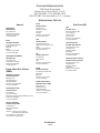
TABLE OF CONTENTS
Safety Statement . . . . . . . . . . . . . . . .2 Required Hardware . . . . . . . . . . . . . . . .8
G7 Warning Labels . . . . . . . . . . . . . . .4 Assembly Instructions . . . . . . . . . . . . . .10
Gym Dimensions. . . . . . . . . . . . . . . . .5 General Maintenance . . . . . . . . . . . . . .24
G7 Live Area . . . . . . . . . . . . . . . . . . .6 Warranty Statement . . . . . . . . . . . . . . .25
Components List . . . . . . . . . . . . . . . . .7 Contact Information . . . . . . . . . . . . . . .26
SAFETY INFORMATION
It is the sole responsibility of the purchaser of LIFE FITNESS products to read the owner's manual, warning labels and
instruct all individuals, whether they are the end user or supervising personnel on proper usage of the equipment.
UNDERSTANDING EACH AND EVERY WARNING TO THE FULLEST IS IMPORTANT. IF ANY OF THESE INSTRUC-
TIONS OR WARNINGS ARE UNCLEAR, CONTACT LIFE FITNESS CUSTOMER SERVICE IMMEDIATELY AT 1-800-
351-3737 WITHIN THE US AND CANADA. INTERNATIONAL OFFICE CONTACT INFORMATION IS AVAILABLE ON
PAGE 26.
Keep children away from strength equipment. Parent or others supervising children must provide close supervision of
children if the equipment is used in the presence of children.
This equipment is categorized as class H per EN 957-1. And as such this equipment is only intended for Home use. It is
not intended for commercial, institutional and/or studio facilities use. Contact LIFE FITNESS with any questions regarding
this classification.
It is recommended that all users of LIFE FITNESS exercise equipment be informed of the following information prior to
use.
ACCESS CONTROL
LIFE FITNESS recommends that all fitness equipment be used in a supervised area. It is recommended that
the equipment be located in an access controlled area. Control is the responsibility of the facility owner.
INSTALLATION
SECURING EQUIPMENT - LIFE FITNESS recommends that all equipment be secured to a solid, level
surface to stabilize and eliminate rocking or tipping over. This must be per formed by a licensed contractor.
PROPER USAGE
1. Do not use any equipment in any way other than as designed or intended by the manufacturer. It is
imperative that LIFE FITNESS equipment is used properly to avoid injury.
2. Injuries may result if exercising improperly or excessively. It is recommended that all individuals consult a
physician prior to commencing an exercise program. If at any time during exercise you feel faint, dizzy or
experience pain, STOP EXERCIZING and consult your physician.
3. Keep body parts (hands, feet, hair, etc.), clothing and jewelry away from moving parts to avoid injury.
4. When adjusting any seat, knee hold down pad, range of motion limiter, foothold pad, pulley or any other
type of adjuster, make certain that the adjusting pin is fully engaged in the hole to avoid injury.

3
INSPECTION
1. DO NOT use or permit use of any equipment that is damaged and or has worn or broken parts. For all
LIFE FITNESS equipment use only replacement parts supplied by LIFE FITNESS.
2. Cables and Belts pose an extreme liability if used when frayed. Always replace any cable at first sign of
wear (consult LIFE FITNESS if uncertain).
3. Routinely inspect all accessory clips that join attachments to the cables and replace at the first sign of
wear.
4. MAINTAIN LABELS AND NAMEPLATES - Do not remove labels for any reason. They contain important
information. If unreadable or missing, contact LIFE FITNESS for a replacement.
5. EQUIPMENT MAINTENANCE - Preventative maintenance is the key to smooth operating equipment as
well as keeping your liability to a minimum. Equipment needs to be inspected at regular intervals.
6. Ensure that any person(s) making adjustments or performing maintenance or repair of any kind is
qualified to do so. LIFE FITNESS will provide service and maintenance training at our corporate facility
upon request or in the field if proper arrangements are made.
7. Before any use, examine all accessories approved for use with the LIFE FITNESS equipment for
damage or wear.
8. DO NOT ATTEMPT TO USE OR REPAIR ANY ACCESSORY APPROVED FOR USE WITH THE LIFE
FITNESS EQUIPMENT WHICH APPEARS TO BE DAMAGED OR WORN.
OPERATING WARNINGS
1. It is the purchaser's sole responsibility to properly instruct its end users and supervising personnel as to
the proper operating procedures of all LIFE FITNESS equipment.
2. Keep children away from strength equipment. Parent or others supervising children must provide close
supervision of children if the equipment is used in the presence of children.
3. Do not allow users to wear loose fitting clothing or jewelry while using equipment. It is also
recommended to have user's secure long hair back and up to avoid contact with moving parts.
4. All bystanders must stay clear of all users, moving parts and attached accessories and components
while machine is in operation.
SELECTORIZED WEIGHT STACK SYSTEMS
1. Use only weight selector pins supplied by LIFE FITNESS on weight stacks. Substitutes are forbidden.
2. Fully insert weight selector pins. Partial insertion can cause weights to fall unexpectedly.
3. Never pin the weight stack in an elevated position.
4. Never remove selector pin if any weights are suspended.
5. Never attempt to release jammed weights or parts.
6. Never use dumbbells or other means to incrementally increase the weight resistance. Use only those
means provided by LIFE FITNESS.

4
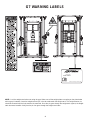
G7 WARNING LABELS
NOTE: Lock the weight stack when not using the gym. Make sure all the weight plates are resting on the plate below
with no gap in between. Insert the weight selector pin in the tab underneath the weight stack. The weight selector pin
should be inserted until the knob touches the metal tab. Once the pin goes through the weight stack system, the weight
stack becomes immobile. Verify that the pin has gone through the weight stack stem.
Schiller Park, IL www.lifefitness.com
Model: FZCP-
Serial Number:
Maximum User Weight: 300 lbs (136kg)
Class: S - Studio

5
GYM DIMENSIONS
Weight: 720 lbs
Resistance Ratio: 1:2
Weight Stack: 160 lbs

6
G7 LIVE AREA
12”
12”
1
0’
18’-8”
NOTE: The live area shows the extent of the G7 gym. It does not include the user.

7
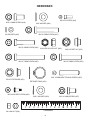
COMPONENTS LIST
ITEM NO. QTY. DESCRIPTION
1 1 LEFT TOWER
2 1 TOP BRACKET TUBE
3 1 MIDDLE BRACKET TUBE
4 1 BOTTOM BRACKET TUBE
5 1 LEFT SLIDE TUBE (WITH ROLLER CARRIAGE) ASSEMBLY
6 1 RIGHT U BRACKET
7 1 LEFT U BRACKET
8 1 RIGHT SWIVEL PULLEY
9 1 LEFT SWIVEL PULLEY
10 1 RIGHT SLIDE TUBE (WITH ROLLER CARRIAGE) ASSEMBLY
11 1 RIGHT TOWER
12 1 CHIN UP BAR
13 16 PULLEY
14 4 PARTIAL PULLEY COVER
15 4 GUIDE ROD RETAINER
16 4 GUIDE ROD ASSEMBLY
17 30 10 LB WEIGHT PLATE
18 2 TOP PLATE
19 2 HEAD PLATE PULLEY ASSEMBLY
20 4 WEIGHT STACK CUSHION
21 2 CABLE
22 2 FOOT EXTENSION
23 2 SIDE SHROUD
24 6 KIOSK BRACKET
25 1 KIOSK ASSEMBLY
26 2 WEIGHT PIN & RING
27 4 FULL PULLEY COVER
28 1 LEFT ROLLER CARRIAGE
29 1 RIGHT ROLLER CARRIAGE
30 2 D RINGS
31 1 THIGH STRAP
32 1 FOOT STRAP
33 1 TOWEL
34 1 MARKER
35 2 HANDLES
36 2 SNAP LINKS
37 1 DVD
38 1 TOUCH-UP PAINT
39 1 EXERCISE BALL
40 1 PUMP
41 1 LONG BAR
42 1 WATER BOTTLE
60 1 EXERCISE BOOKLET

8
COMPONENTS LIST
HARDWARE
ITEM NO. QTY. DESCRIPTION
43 32 M10 X 20MM SCREW
44 58 M10 WASHER
45 20 M5 HEX SCREW
46 20 M6 WASHER
47 4 M10 X 55MM SCREW
48 2 M10 X 45MM SCREW
49 13 M10 HEX NYLOCK NUT
50 7 M10 X 70MM SCREW
51 2 M10 SOCKET HEAD NUT
52 2 M10 X 50MM SCREW
53 2 PULLEY RETAINER
54 4 RETAINER RING
55 4 M10 X 50MM HEX TENSION SCREW
56 32 M5 SHOULDER SCREW
57 12 M10 X 16MM SCREW
58 12 M10.5 WASHER
59 2 .500-13 JAM NUT
BLISTER PACKS
Blister Pack 7-1 1
Blister Pack 7-2 1
Blister Pack 7-3 1
Blister Pack 7-4 1
Blister Pack 7-5 1
Blister Pack 7-6 1
REQUIRED TOOLS
ADJUSTABLE WRENCH
EXTERNAL SNAP RING PLIERS
PHILLIPS SCREW DRIVER
ALLEN WRENCHES (4mm, 5mm, 7mm)
WRENCH (17mm)

9
HARDWARE:
M10 X 50MM HEX TENSION SCREW (#55)
M10 HEX NYLOCK NUT (#49)
M10 SOCKET NUT (#51)
M10 WASHER (#44)
M10.5 WASHER (#58)
M10 X 20MM SCREW (#43)
M5 HEX SCREW (#45)
M5 SHOULDER SCREW (#56)
M6 WASHER (#46)
PULLEY RETAINER (#53)
RETAINER RING (#54)
M10 X 45MM SCREW (#48)
M10 X 70MM SCREW (#50)
M10 X 50MM SCREW (#52)
M10 X 55MM SCREW (#47)
M10 X 16MM SCREW (#57)
M6 JAM NUT (#59)
Centimeters

10
1
44 43
4443
2
3
11
4
44
43
4443
1
11
A
B
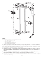
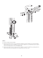
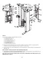
NOTE: Two person assembly is recommended.
STEP 1:
Use the following hardware contained in Blister Pack (7-1):
M10 x 20mm SCREW (Qty. 24)
M10 WASHER (Qty. 24)
Make sure the LEFT TOWER (1) and the RIGHT TOWER (11) are positioned correctly prior to assembly. The LEFT
U BRACKET (A) and RIGHT U BRACKET (B) should point towards each other as shown in the above illustration.
Use four M10 x 20mm SCREWS (43) and four M10 WASHERS (44) to connect the BOTTOM BRACKET TUBE (4)
to the LEFT TOWER (1). Finger tighten only.
NOTE: THE BOTTOM BRACKET TUBE (4) HAS A RUBBER PAD ATTACHED TO IT TO MAKE CONTACT WITH THE
FLOOR.
Repeat the above process using the TOP BRACKET TUBE (2) and the MIDDLE BRACKET TUBE (3).
NOTE: THE TOP BRACKET TUBE (2) DOES NOT HAVE ANY HOLES. THE MIDDLE BRACKET TUBE (3) HAS
THREE HOLES THROUGH THE TOP AND BOTTOM.
Repeat all of the above steps to attach the TOP (2), MIDDLE (3), and BOTTOM (4) BRACKET TUBES to the RIGHT
TOWER (11).

11
12
50
44
44
49
1
11
44
50
STEP 2:
Use the following hardware contained in Blister Pack (7-1):
M10 x 70mm SCREW (Qty. 4)
M10 WASHER (Qty. 8)
M10 HEX NYLOCK NUT (Qty. 4)
Attach the CHIN UP BAR (12) between the LEFT TOWER (1) and RIGHT TOWER (11) using four M10 x 70mm
SCREWS (50), eight M10 WASHERS (44), and four M10 HEX NYLOCK NUTS (49). Finger tighten only.
NOTE: Make sure the CHIN UP BAR (12) is in the correct position as shown.
Tighten all FRAME and CHIN UP BAR screws and nuts securely.

12
STEP 3:
Use the following hardware contained in Blister Pack (7-2):
M10 x 45mm SCREW (Qty. 2)
M10 WASHER (Qty. 8)
M10 HEX NYLOCK NUT (Qty. 4)
M10 x 55mm SCREW (Qty. 2)
Slide the top of the LEFT SLIDE TUBE ASSEMBLY (5) over the UPPER BRACKET (C) on the LEFT TOWER (1).
NOTE: MAKE SURE THE ENGRAVED NUMBERS ON THE LEFT SLIDE TUBE ASSEMBLY (5) FACE THE INSIDE
OF THE GYM. NOTE THE ORIENTATION OF THE CARRIAGE.
Secure the LEFT SLIDE TUBE ASSEMBLY (5) to the UPPER BRACKET (C) of the LEFT TOWER (1) using one
M10 x 45mm SCREW (48), two M10 WASHERS (44), and one M10 HEX NYLOCK NUT (49). Do not tighten at
this time.
Secure the LEFT SLIDE TUBE ASSEMBLY (5) to the LOWER BRACKET (D) of the LEFT TOWER (1) using one
M10 x 55mm SCREW (47), two M10 WASHERS (44), and one M10 HEX NYLOCK NUT (49).
Repeat the above process to secure the RIGHT SLIDE TUBE ASSEMBLY (10) to the RIGHT TOWER (11). Tighten
all nuts and screws securely.
5
1
48
44
C
44
49
D
44
49
44
47
10
11
28
29

13
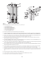
STEP 4:
Use the following hardware contained in Blister Pack (7-2):
M5 SHOULDER SCREW (Qty. 32)
M5 HEX SCREW (Qty. 8)
M6 WASHER (Qty. 8)
Remove the protective paper from the SIDE SHROUD (23) before installation.
Install one SIDE SHROUD (23) to the RIGHT TOWER (11) using sixteen M5 SHOULDER SCREWS (56) on the
inside of the SIDE SHROUD (23) into the UPRIGHT TUBES (E) of the RIGHT TOWER (11). Tighten the screws
securely.
NOTE: YOU MUST BE STANDING INSIDE THE GYM TO INSTALL THE SIDE SHROUD (23).
Repeat this process for installing one SIDE SHROUD (23) to the LEFT TOWER (1).
Attach the RIGHT U BRACKET (6) onto the back of the UPRIGHT TUBE (E) of the RIGHT TOWER (11) using four
M5 HEX SCREWS (45) and four M6 WASHERS (46). Tighten the screws securely.
Repeat this process for installing the LEFT U BRACKET (7) onto the back of the UPRIGHT TUBE (F) of the LEFT
TOWER (1).
E
56
23
6
45
46
F
1
11
7

14
55
15
54
18
17
G
20
16
11
19
26
59
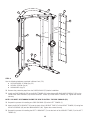
STEP 5:
Use the following hardware contained in Blister Pack (7-3):
M10 x 50mm HEX TENSION SCREW (Qty. 4)
GUIDE ROD RETAINER (Qty. 4)
RETAINER RING (Qty. 4)
NOTE: INSTALL FROM THE INSIDE OF THE UNIT.
Position two WEIGHT STACK CUSHIONS (20) and GUIDE RODS (16) at the GUIDE ROD BRACKET (G) on the
RIGHT TOWER (11) as shown.
NOTE: MAKE SURE THAT THE PLUGGED END OF THE GUIDE RODS (16) ARE FACING UP.
Slide one WEIGHT PLATE (17) over the GUIDE RODS (16) and slowly lower the WEIGHT PLATE (17) onto the
WEIGHT STACK CUSHIONS (20).
Continue stacking a total of fifteen WEIGHT PLATES (17).
Slide one TOP PLATE (18) over the GUIDE RODS (16) and slowly lower it onto the WEIGHT PLATES (17).
Slide one WEIGHT PIN with RING (26) over the stem of the TOP PLATE (18).
Thread the HEAD PLATE PULLEYASSEMBLY (19) into the TOP PLATE (18). Do not tighten! This will be adjusted
later. Make sure the JAM NUT (59) is threaded onto the HEAD PLATE PULLEY ASSEMBLY (19) before threading
into the TOP PLATE (18).
Slide one RETAINER RING (54) over each of the GUIDE RODS (16).
Thread an M10 x 50mm HEX TENSION SCREW (55) into each of the two GUIDE ROD RETAINERS (15). Do not
fully thread the M10 x 50mm HEX TENSION SCREWS (55) into the GUIDE ROD RETAINERS (15).
Slide the GUIDE ROD RETAINERS (15) into the holes on the RIGHT TOWER (11). Make sure the M10 x 50mm
HEX TENSION SCREWS (55) in the GUIDE ROD RETAINERS (15) are facing up.
Push the GUIDE ROD RETAINERS (15) up high enough so that the GUIDE RODS (16) can be placed under
them.
Lower the GUIDE ROD RETAINERS (15) over the GUIDE RODS (16).
Slide the RETAINER RINGS (54) up. Use a RETAINING RING PLIER to secure the RETAINER RINGS (54) into
the groove on the GUIDE ROD RETAINERS (15). If the groove is hidden inside the hole on the tube, use a 5mm
ALLEN WRENCH to loosen the M10 x 50mm HEX TENSION SCREW (55) until the groove is accessible.
Repeat this step to complete the LEFT TOWER assembly.
NOTE: The Side Shroud is not shown in
this illustration for clarity.

15
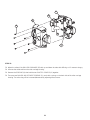
STEP 6:
Uncoil the cables to remove all twists.
Remove the (UPPER) PULLEYS (13) on the RIGHT TOWER (11) and LEFT TOWER (1) by removing the M10 x
50mm SCREW (52), PULLEY RETAINER (53), M10 SOCKET HEAD NUT (51), and PARTIAL PULLEY COVERS
(14). Set the (UPPER) PULLEYS (13) and hardware aside.
Remove the (LOWER) PULLEYS (13) on the RIGHT TOWER (11) and LEFT TOWER (1) by removing the M10 x
45mm SCREW (48), two M10 WASHERS (44), and M10 HEX NYLOCK NUT (49).
48
44
44
49
13
Lower Pulley
14
53
52
51
14
13
Upper Pulley

16
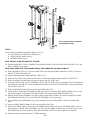
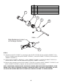
STEP 7:
Use the following hardware contained in Blister Packs (7-3), (7-4) and (7-5):
M10 WASHER (Qty. 4)
M10 HEX NYLOCK NUT (Qty. 2)
M10 x 45mm SCREW (Qty. 2)
M10 SOCKET HEAD NUT (Qty. 2)
M10 x 50mm SCREW (Qty. 2)
PULLEY RETAINER (Qty. 2)
Remove the JAM NUT (59) from the threaded end of the CABLE (21).
Lower the threaded end of the CABLE (21) down the long vertical tube that is in front of the gym until it can be retrieved near
where the (LOWER) PULLEY (13) was located. Carefully pull enough cable out to reach the RIGHT ROLLER CARRIAGE (29).
INSTALL the (LOWER) PULLEY (13) using the M10 x 45mm SCREW (48), two M10 WASHERS (44), and M10 HEX NYLOCK
NUT (49). Be sure that the CABLE (21) is properly routed around the (LOWER) PULLEY (13).
Bring the threaded end of the CABLE (21) up to the RIGHT ROLLER CARRIAGE (29) and thread the CABLE (21) into the
RIGHT ROLLER CARRIAGE (29). Do not tighten!
Assemble the (MIDDLE UPPER) PULLEY (13) by using two FULL PULLEY COVERS (14), one PULLEY RETAINER (53), one
M10 SOCKET HEAD NUT (51) and one M10 x 50mm SCREW (52).
Feed the cable end with the small ball between the MIDDLE UPPER PULLEY BRACKET (H) and then through the forward most
hole in the MIDDLE BRACKET TUBE (3) above the HEAD PLATE PULLEY ASSEMBLY (19).
Take the CABLE (21) down and around the HEAD PLATE PULLEY (19) and back up through the MIDDLE BRACKET TUBE (3)
again, passing through the remaining access hole.
Feed the CABLE (21) around where the (UPPER) PULLEY (13) of the RIGHT TOWER (11) was located. Forward the CABLE
(21) through the TOP BRACKET TUBE (2) and out the access hole where the (UPPER) PULLEY (13) was located.
REINSTALL the (UPPER) PULLEY (13) using the previously removed M10 x 50mm SCREW (I), PULLEY RETAINER (J), M10
SOCKET HEAD NUT (K), and PARTIAL PULLEY COVER (L). Be sure that the CABLE (21) is properly routed around the PUL-
LEY.
Bring the CABLE (21) down to the RIGHT ROLLER CARRIAGE (29).
Feed the CABLE (21) through the two pulleys in the RIGHT ROLLER CARRIAGE (29) as shown.
Repeat Step 6 to route the cable through the LEFT TOWER (1).
21
2
3
29
19
13
13
13
59
Lower Pulley
Upper Pulley
Middle Upper Pulley
27
53
38
14
53
52
51
27
13
51
14
13
H
Middle Upper Pulley
Upper Pulley

Slide Mechanism to insert
or Exchange Handles
Cable
K
M
J
L
K
I
17
STEP 8:
Dissemble one QUICK CONNECT by removing the two M5 HEX SCREWS (M) from the QUICK CONNECT COU-
PLER (I). Carefully remove the QUICK CONNECT SPRING (L), the QUICK CONNECT SLEEVE (K) and the QUICK
CONNECT HOUSING (J).
Slide the QUICK CONNECT HOUSING (J), QUICK CONNECT SPRING (L), and QUICK CONNECT SLEEVE (K)
onto the cable as shown. Insert the cable end into the QUICK CONNECT COUPLER (I).
Slide the entire assembly over the QUICK CONNECT COUPLER (I). Attach the QUICK CONNECT COUPLER (I) and
QUICK CONNECT HOUSING (J) together. Use the two M5 HEX SCREWS (M) to tighten.
NOTE: IF NECESSARY, ENSURE CABLES ARE PROPER LENGTH; MAKE NECESSARY ADJUSTMENTS TO THE
WEIGHT STACK PULLEY (TIGHTEN OR LOOSEN); THREAD THE END OF THE CABLE; AND REMOVE THE PUL-
LEY FROM THE HOUSING AND SPIN CLOCKWISE OR COUNTER CLOCKWISE TO LOOSEN/TIGHTEN.
ITEM QTY DESCRIPTION
I 1 QUICK CONNECT COUPLER
J 1 QUICK CONNECT HOUSING
K 1 QUICK CONNECT SLEEVE
L 1 QUICK CONNECT SPRING
M 2 M5 HEX SCREW

18
STEP 9:
Make adjustments to the HEAD PLATE PULLEY (19) and the threaded cable end to adjust cable length and to
ensure the cable is taut.
If the threaded cable end is completely threaded into the LEFT ROLLER CARRIAGE (28) and there is still some
slack in the CABLE (21), remove the pulley from the HEAD PLATE PULLEY (19). Thread the HEAD PLATE PULLEY
(19) further into the TOP PLATE ASSEMBLY (18) and reinstall the pulley.
Once the CABLE (21) is taut, engage the jam nut at the threaded end of the cable as well as at the HEAD PLATE
PULLEY ASSEMBLY (19).
28
19
18
21

19
22
44
43
43
44
1
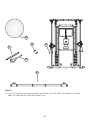
STEP 10:
Use the following hardware contained in Blister Pack (7-4):
M10 x 20mm SCREW (Qty. 8)
M10 WASHER (Qty. 8)
Install one FOOT EXTENSION (22) to the bottom of the LEFT TOWER (1) using four M10 x 20mm SCREWS (43)
and four M10 WASHERS (44).
Repeat the above step to attach the other FOOT EXTENSION (22) to the bottom of the RIGHT TOWER (11).

20
11
3
25
46
45 58
57
24
50
44
44
49
3
25
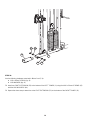
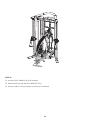
STEP 11:
Use the following hardware contained in Blister Pack (7-6):
M5 HEX SCREW (Qty. 12)
M6 WASHER (Qty. 12)
M10 x 16mm SCREW (Qty. 12)
M10.5 WASHER (Qty. 12)
M10 x 70mm SCREW (Qty. 3)
M10 WASHER (Qty. 6)
M10 HEX NYLOCK NUT (Qty. 3)
Attach the six KIOSK BRACKETS (24) to the RIGHT TOWER (11) and LEFT TOWER (1) using two M5 HEX
SCREWS (45) and two M6 WASHERS (46) each. Tighten the screws securely.
Fasten the KIOSK (25) to the KIOSK BRACKETS (24) using twelve M10 x 16mm SCREWS (57) and twelve M10.5
WASHERS (58).
NOTE: SUPPORT THE KIOSK (25) UNTIL THE SCREWS ARE INSTALLED.
Secure the top of the KIOSK (25) to the MIDDLE BRACKET TUBE (3) using three M10 x 70mm SCREWS (50), six
M10 WASHERS (44), and three M10 HEX NYLOCK NUTS (49).
NOTE: THE TOP OF THE KIOSK (25) HAS THREE SLOTS THAT FIT UNDERNEATH THE THREE HOLES OF THE
MIDDLE BRACKET TUBE (3).
Page is loading ...
Page is loading ...
Page is loading ...
Page is loading ...
Page is loading ...
Page is loading ...
-
 1
1
-
 2
2
-
 3
3
-
 4
4
-
 5
5
-
 6
6
-
 7
7
-
 8
8
-
 9
9
-
 10
10
-
 11
11
-
 12
12
-
 13
13
-
 14
14
-
 15
15
-
 16
16
-
 17
17
-
 18
18
-
 19
19
-
 20
20
-
 21
21
-
 22
22
-
 23
23
-
 24
24
-
 25
25
-
 26
26


Life Fitness 39735 User manual
- Type
- User manual
Ask a question and I''ll find the answer in the document
Finding information in a document is now easier with AI
Related papers
-
Life Fitness lifefitness g7 User manual
-
-
-
-
-
-
-
-
-
Other documents
-
 Frigiking 05-002-0248 Operating instructions
-
Premier Mounts PVUM User manual
-
York Fitness 50037 Owner's manual
-
-
-
-
-
Weslo Gym 2500 User manual
-
Gold's Gym Platinum GGSY3058.0 User manual
-
