Supermicro Supero X8DAH+ User manual
- Category
- Motherboards
- Type
- User manual

USER’S MANUAL
Revision 1.0c
X8DAH+-F
X8DAH+

Manual Revision 1.0c
Release Date: April 26, 2010
Unless you request and receive written permission from Super Micro Computer, Inc., you may not
copy any part of this document.
Information in this document is subject to change without notice. Other products and companies
referred to herein are trademarks or registered trademarks of their respective companies or mark
holders.
Copyright © 2010 by Super Micro Computer, Inc.
All rights reserved.
Printed in the United States of America
The information in this User’s Manual has been carefully reviewed and is believed to be accurate.
The vendor assumes no responsibility for any inaccuracies that may be contained in this document,
makes no commitment to update or to keep current the information in this manual, or to notify any
person or organization of the updates. Please Note: For the most up-to-date version of this
manual, please see our website at www.supermicro.com.
Super Micro Computer, Inc. ("Supermicro") reserves the right to make changes to the product
described in this manual at any time and without notice. This product, including software and docu-
mentation, is the property of Supermicro and/or its licensors, and is supplied only under a license.
Any use or reproduction of this product is not allowed, except as expressly permitted by the terms
of said license.
IN NO EVENT WILL SUPER MICRO COMPUTER, INC. BE LIABLE FOR DIRECT, INDIRECT,
SPECIAL, INCIDENTAL, SPECULATIVE OR CONSEQUENTIAL DAMAGES ARISING FROM THE
USE OR INABILITY TO USE THIS PRODUCT OR DOCUMENTATION, EVEN IF ADVISED OF
THE POSSIBILITY OF SUCH DAMAGES. IN PARTICULAR, SUPER MICRO COMPUTER, INC.
SHALL NOT HAVE LIABILITY FOR ANY HARDWARE, SOFTWARE, OR DATA STORED OR USED
WITH THE PRODUCT, INCLUDING THE COSTS OF REPAIRING, REPLACING, INTEGRATING,
INSTALLING OR RECOVERING SUCH HARDWARE, SOFTWARE, OR DATA.
Any disputes arising between manufacturer and customer shall be governed by the laws of Santa
Clara County in the State of California, USA. The State of California, County of Santa Clara shall be
the exclusive venue for the resolution of any such disputes. Supermicro's total liability for all claims
will not exceed the price paid for the hardware product.
FCC Statement: This equipment has been tested and found to comply with the limits for a Class
A digital device pursuant to Part 15 of the FCC Rules. These limits are designed to provide
reasonable protection against harmful interference when the equipment is operated in a commercial
environment. This equipment generates, uses, and can radiate radio frequency energy and, if not
installed and used in accordance with the manufacturer’s instruction manual, may cause harmful
interference with radio communications. Operation of this equipment in a residential area is likely
to cause harmful interference, in which case you will be required to correct the interference at your
own expense.
California Best Management Practices Regulations for Perchlorate Materials: This Perchlorate
warning applies only to products containing CR (Manganese Dioxide) Lithium coin cells. “Perchlorate
Material-special handling may apply. See www.dtsc.ca.gov/hazardouswaste/perchlorate”.
WARNING: Handling of lead solder materials used in this
product may expose you to lead, a chemical known to
the State of California to cause birth defects and other
reproductive harm.

Preface
About this Manual
This manual is written for system integrators, PC technicians and knowledgeable PC
users. It provides information for the installation and use of the
X8DAH+/
X8DAH+-F motherboard.
About this Motherboard
The X8DAH+/X8DAH+-F supports the Intel® 5500/5600 Series Proces-
sor platform, the fi rst dual-processing platform that supports the Intel QuickPath
Interconnect (QPI) Technology, providing the next generation point-to-point system
interface to replace the current Front Side Bus. With the Intel 5520 chipset built in,
the X8DAH+/X8DAH+-F substantially enhances system performance with increased
bandwidth and unprecedented scalability optimized for HPC/Cluster systems and
intensive applications. Please refer to our website (http://www.supermicro.com/
products/) for updates on supported processors. This product is intended to be
installed and serviced by professional technicians.
Manual Organization
Chapter 1 describes the features, specifi cations and performance of the mother-
board and provides detailed information about the chipset.
Chapter 2 provides hardware installation instructions. Read this chapter when in-
stalling the processor, memory modules and other hardware components into the
system. If you encounter any problems, see Chapter 3, which describes trouble-
shooting procedures for video, memory and system setup stored in the CMOS.
Chapter 4 includes an introduction to the BIOS and provides detailed information
on running the CMOS Setup utility.
Appendix A lists BIOS POST Error Codes. Appendix B and Appendix C provide
the Windows OS and Other Software Installation Instructions.
iii
Preface

Conventions Used in the Manual
Special attention should be given to the following symbols for proper installation and
to prevent damage done to the components or injury to yourself.
Danger/Caution: Instructions to be strictly followed to prevent catastrophic
system failure or to avoid bodily injury.
Warning: Important information given to ensure proper system installation
or to prevent damage to the components.
Note: Additional Information given to differentiate various models or to
ensure correct system setup.
X8DAH+/X8DAH+-F User's Manual
iv

Contacting Supermicro
v
Contacting Supermicro
Headquarters
Address: Super Micro Computer, Inc.
980 Rock Ave.
San Jose, CA 95131 U.S.A.
Tel: +1 (408) 503-8000
Fax: +1 (408) 503-8008
Email: [email protected] (General Information)
[email protected] (Technical Support)
Website: www.supermicro.com
Europe
Address: Super Micro Computer B.V.
Het Sterrenbeeld 28, 5215 ML
's-Hertogenbosch, The Netherlands
Tel: +31 (0) 73-6400390
Fax: +31 (0) 73-6416525
Email: [email protected] (General Information)
[email protected] (Technical Support)
[email protected] (Customer Support)
Asia-Pacifi c
Address: Super Micro Computer, Inc.
4F, No. 232-1, Liancheng Rd.
Chung-Ho 235, Taipei County
Taiwan, R.O.C.
Tel: +886-(2) 8226-3990
Fax: +886-(2) 8226-3991
Website: www.supermicro.com.tw
Technical Support:
Email: [email protected]
Tel: 886-2-8228-1366, ext.132 or 139

X8DAH+/X8DAH+-F User's Manual
vi
Table of Contents
Preface
Chapter 1 Introduction
1-1 Overview .........................................................................................................1-1
1-2 Chipset Overview ..........................................................................................1-10
1-3 Special Features ............................................................................................1-11
1-4 PC Health Monitoring .....................................................................................1-11
1-5 ACPI Features ...............................................................................................1-12
1-6 Power Supply ................................................................................................1-13
1-7 Super I/O .......................................................................................................1-13
1-8 Overview of the Winbond WPCM450 Controller (For X8DAH+-F Only) ...... 1-14
Chapter 2 Installation
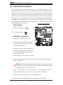
2-1 Static-Sensitive Devices .................................................................................. 2-1
2-2 Motherboard Installation ..................................................................................2-2
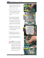
2-3 Processor and Heatsink Installation................................................................2-3
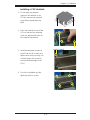
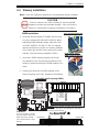
2-4 Memory Installation ........................................................................................2-7
2-5 Control Panel Connectors/IO Ports...............................................................2-12
1. Back Panel Connectors/IO Ports .............................................................. 2-12
ATX PS/2 Keyboard and PS/2 Mouse Ports ............................................2-13
Serial Ports ............................................................................................... 2-14
Video Connector .......................................................................................2-14
Universal Serial Bus (USB) ...................................................................... 2-15
Ethernet Ports ..........................................................................................2-16
(Back_Panel) High Defi nition Audio (HD Audio) .....................................2-17
CD &10-pin Audio Headers ..................................................................... 2-17
2. Front Control Panel ................................................................................... 2-18
3. Front Control Panel Pin Defi nitions .......................................................... 2-19
NMI Button ...............................................................................................2-19
Power LED ..............................................................................................2-19
HDD LED ..................................................................................................2-20
NIC1/NIC2 LED Indicators .......................................................................2-20
Overheat (OH)/Fan Fail LED....................................................................2-21
Power Fail LED ........................................................................................2-21
Reset Button ...........................................................................................2-22
Power Button ...........................................................................................2-22
2-6 Connecting Cables ........................................................................................2-23
Power Connectors ................................................................................... 2-23

Table of Contents
vii
Fan Headers .............................................................................................2-24
Chassis Intrusion .....................................................................................2-24
Internal Speaker .......................................................................................2-25
Power LED/Speaker .................................................................................2-25
Overheat LED/Fan Fail (JOH1) ................................................................2-26
System Management Bus ........................................................................ 2-27
Power SMB (I
2
C) Connector .................................................................... 2-27
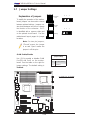
2-7 Jumper Settings ............................................................................................2-28
Explanation of Jumpers ................................................................................ 2-28
GLAN Enable/Disable .............................................................................. 2-28
CMOS Clear ............................................................................................. 2-29
Watch Dog Enable/Disable ...................................................................... 2-29
I
2
C Bus to PCI-Exp. Slots ........................................................................2-30
VGA Enable .............................................................................................. 2-31
1394a-1/1394a-2 Enable ..........................................................................2-31
2-8 Onboard LED Indicators ............................................................................... 2-32
GLAN LEDs .............................................................................................. 2-32
IPMI Dedicated LAN LEDs (X8DAH+-F) .................................................. 2-32
Onboard Power LED ............................................................................... 2-33
BMC Heartbeat LED (X8DAH+-F) ........................................................... 2-33
2-9 Floppy Drive, Serial ATA and SAS Connections ........................................... 2-34
Floppy Connector ..................................................................................... 2-34
Serial ATA Ports........................................................................................ 2-36
Chapter 3 Troubleshooting
3-1 Troubleshooting Procedures ........................................................................... 3-1
Before Power On ............................................................................................ 3-1
No Power ........................................................................................................3-1
No Video .........................................................................................................3-2
Losing the System’s Setup Confi guration .......................................................3-2
Memory Errors ............................................................................................... 3-2
3-2 Technical Support Procedures ........................................................................ 3-3
3-3 Frequently Asked Questions ...........................................................................3-3
3-4 Returning Merchandise for Service.................................................................3-4
Chapter 4 BIOS
4-1 Introduction ......................................................................................................4-1
Starting BIOS Setup Utility .............................................................................. 4-1
How To Change the Confi guration Data ......................................................... 4-1
Starting the Setup Utility ................................................................................. 4-2

X8DAH+/X8DAH+-F User's Manual
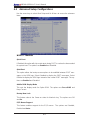
4-2 Main Setup ......................................................................................................4-2
4-3 Advanced Setup Confi gurations......................................................................4-4
4-4 Security Settings ........................................................................................... 4-24
4-5 Boot Confi guration ........................................................................................4-25
4-6 Exit Options ................................................................................................... 4-27
4-7 BIOS Recovery ............................................................................................. 4-29
How to Recover the AMIBIOS Image (-the Main BIOS Block) .....................4-29
4.7.1 Boot Sector Recovery from a USB Device .......................................... 4-29
4.7.2 Boot Sector Recovery from an IDE CD-ROM .....................................4-30
4.7.3 Boot Sector Recovery from a Serial Port ("Serial Flash") ................... 4-30
Appendix A BIOS Error Beep Codes
A-1 BIOS Error Beep Codes .................................................................................A-1
Appendix B Installing the Windows OS
B-1 Installing the Windows OS to a RAID System ................................................B-1
B-2 Installing the Windows OS to a Non-RAID System ........................................B-2
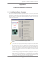
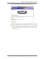
Appendix C Software Installation Instructions
C-1 Installing Software Programs .........................................................................C-1
C-2 Confi guring Supero Doctor III .........................................................................C-2
viii

Chapter 1: Introduction
1-1
Chapter 1
Introduction
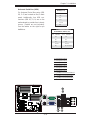
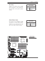
1-1 Overview
Checklist
Congratulations on purchasing your computer motherboard from an acknowledged
leader in the industry. Supermicro boards are designed with the utmost attention
to detail to provide the highest standards in quality and performance. Check that
the following items have all been included with your motherboard. If anything listed
here is damaged or missing, contact your retailer.
The following items are included in the retail box.
One (1) Supermicro Mainboard
•
One (1) fl oppy ribbon cable (CBL-022L) •
One (1) IDE ATA66 cable (CBL-036L-03)•
Six (6) Serial ATA cables (CBL-0044L)•
One I/O backpanel shield (MCP-260-00025-0N) •
One (1) Supermicro CD containing drivers and utilities•
One (1) User's/BIOS Manual•

1-2
X8DAH+/X8DAH+-F User's Manual
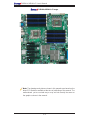
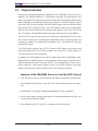
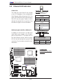
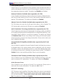
X8DAH+/X8DAH+-F Image
Note: The drawings and pictures shown in this manual were based on the
latest PCB Revision available at the time of publishing of the manual. The
motherboard you’ve received may or may not look exactly the same as
the graphics shown in the manual.

Chapter 1: Introduction
1-3
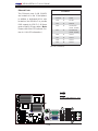
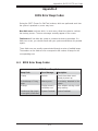
Differences between X8DAH+/X8DAH+-F
X8DAH+ X8DAH+-F
SATA (ICH10R) Yes Yes
IPMI 2.0 w/KVM No Yes
WPCM450 BMC No Yes
Dedicated LAN & PHY chip No Yes
Notes:
1. IPMI 2.0, WPCM450 BMC Controller, the PHY chip and Dedicated
LAN port w/KVM support are available on the X8DAH+-F only. For more
information, refer to the user guide posted on our website @ http://www.
supermicro.com/support/manuals/.
2. The I-FAN 1 and I-FAN2 are available for a R. 2.0 or later version
motherboard only.
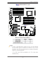
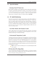
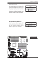
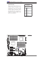
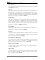
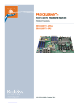
X8DAH+/X8DAH+-F Layout
JBT1
1
DP5
A
JPI2C1
CNF1
USB6/7
JLPC80
VGA (Top)
AUDIO
JPI1
JPG1
JWD1
JPT1
JPW2
JPW3
JPW1
SP1
FAN2
FAN6
FAN5
J14
JBAT1
JOH1
JL1
JI2C2
JI2C1
JD1
KB/MS
CD1
JIDE1
USB
2/3/4/5
JUSB2
SMBUS1
ALWAYS POPULATE DIMM1 FIRST
Slot7 PCI-E 2.0 x8
FAN3
FAN1
P2 DIMM3A
P2 DIMM3B
P2 DIMM2B
P2 DIMM2C
P2 DIMM2A
P2 DIMM3C
P2 DIMM1B
P2 DIMM1C
P2 DIMM1A
P1 DIMM3C
P1 DIMM3B
P1 DIMM2C
P1 DIMM2B
P1 DIMM1C
P1 DIMM1B
P1 DIMM3A
P1 DIMM2A
P1 DIMM1A
ALWAYS POPULATE DIMM1 FIRST
CPU2 FAN
FLOPPY
IDE
I-SATA5
I-S ATA4
I-S ATA3
I-S ATA2
I-S ATA1
Slot6 PCI-E 2.0 x16
Slot5 PCI-E 2.0 x4 (in x8 Slot)
Slot4 PCI-E 2.0 x8 (in x16 Slot)
Slot3 PCI-E 2.0 x8
Slot2 PCI-E 2.0 x16
LAN2 (Top)
COM1
(Bottom)
I-S ATA0
PWR I2C
CPU1
CPU2
USB0/1
LAN1
COM2
Slot1 PCI-E 2.0 x8
DP4
CNF2
BIOS
FAN4
FPCTL
JF1
FAN7
FAN1
CPU
LAN
CTRL
BMC
Audio
CTRL
BMC
Firmware
CTRL
Intel
IOH-36D
Intel
ICH 10R
Intel
(SouthBridge)
X8DAH+
AUDIO
Header
7.1HD
BMC Graphics
Memory
S I/O
1394
CTRL
1394-1 1394-2
IPMI LAN
PHY
Chip
JPL1
J15
J139
JP4
JP5
JUSB5
JUSB4
Rev. 2.0
IOH-36D
(Bottom)
JP9
I-FAN1
I-FAN2

1-4
X8DAH+/X8DAH+-F User's Manual
Jumpers not indicated are for test purposes only. 1.
" " indicates the location of Pin 1.2.
When DP4 is on, the onboard power connection is on. Make sure to unplug 3.
the power cables before removing or installing components.
Warning:
1. To prevent damage to the power supply or motherboard, please use
a power supply that contains a 24-pin and two 8-pin power connectors.
Be sure to connect these connectors to the 24-pin (JPW1) and the two
8-pin (JPW2,JPW3) power connectors on the motherboard. Failure in
doing so will void the manufacturer warranty on your power supply and
motherboard.
2. To prevent system overheating, be sure to provide adequate airfl ow to
the system.
Notes
Quick Reference
JBT1
1
DP5
A
JPI2C1
CNF1
USB6/7
JLPC80
VGA (Top)
AUDIO
JPI1
JPG1
JWD1
JPT1
JPW2
JPW3
JPW1
SP1
FAN2
FAN6
FAN5
J14
JBAT1
JOH1
JL1
JI2C2
JI2C1
JD1
KB/MS
CD1
JIDE1
USB
2/3/4/5
JUSB2
SMBUS1
ALWAYS POPULATE DIMM1 FIRST
Slot7 PCI-E 2.0 x8
FAN3
FAN1
P2 DIMM3A
P2 DIMM3B
P2 DIMM2B
P2 DIMM2C
P2 DIMM2A
P2 DIMM3C
P2 DIMM1B
P2 DIMM1C
P2 DIMM1A
P1 DIMM3C
P1 DIMM3B
P1 DIMM2C
P1 DIMM2B
P1 DIMM1C
P1 DIMM1B
P1 DIMM3A
P1 DIMM2A
P1 DIMM1A
ALWAYS POPULATE DIMM1 FIRST
CPU2 FAN
FLOPPY
IDE
I-SATA5
I-S ATA 4
I-S ATA 3
I-S ATA 2
I-S ATA 1
Slot6 PCI-E 2.0 x16
Slot5 PCI-E 2.0 x4 (in x8 Slot)
Slot4 PCI-E 2.0 x8 (in x16 Slot)
Slot3 PCI-E 2.0 x8
Slot2 PCI-E 2.0 x16
LAN2 (Top)
COM1
(Bottom)
I-S ATA 0
PWR I2C
CPU1
CPU2
USB0/1
LAN1
COM2
Slot1 PCI-E 2.0 x8
DP4
CNF2
BIOS
FAN4
FPCTL
JF1
FAN7
FAN1
CPU
LAN
CTRL
BMC
Audio
CTRL
BMC
Firmware
CTRL
Intel
IOH-36D
Intel
ICH 10R
Intel
(SouthBridge)
X8DAH+
AUDIO
Header
7.1HD
BMC Graphics
Memory
S I/O
1394
CTRL
1394-1 1394-2
IPMI LAN
PHY
Chip
JPL1
J15
J139
JP4
JP5
JUSB5
JUSB4
Rev. 2.0
IOH-36D
(Bottom)
JP9
I-FAN1
I-FAN2

Chapter 1: Introduction
1-5
X8DAH+/X8DAH+-F Quick Reference
Jumper Description Default Setting
JBT1 CMOS Clear Open (Normal)
JPIDE1 Compact Flash Enabled Pins 1-2 (Enabled)
JI
2
C1/JI
2
C2 SMB to PCI/PCI-E Slots Open/Open (Disabled)
JPG1 VGA Enable Pins 1-2 (Enabled)
JPI1 1394-1/1394 Enable Pins 1-2 (Enabled)
JPL1 LAN1/2 Enable Pins 1-2 (Enabled)
JWD1 Watch Dog Pins 1-2 (Reset)
Connector Description
CNF1/CNF2 1394a-1/-2 Ports
Audio Connections BP 7.1 HD Audio, BP Audio Header, CD_In
COM1/COM2 Backplane Serial Port/FP Serial Header
FAN 1-8 System/CPU Fan Headers (Fans 7~8: CPU Fans 1/2)
I-FAN 1/2 Fans 1/2 Headers for IOH Chips 1/2
Floppy Floppy Drive
IDE IDE Drive
JD1 PWR LED/Speaker Header (Pins 1~3: Power LED, Pins
6~7: Onboard Buzzer, Pins 4~7: External Speaker)
JF1 Front Panel Connector
JL1 Chassis Intrusion Header
JOH1 Overheat LED Header
JPI
2
C Power Supply SMBbus I
2
C Header
JPW1, JPW2/JPW3 24-pin ATX PWR, 8-pin Secondary PWR (See Warning on
Page 1-4)
LAN1/2, Dedicated LAN G-LAN (RJ45) Ports (Dedicated LAN: X8DAH+-F)
I-SATA0 ~ I-SATA5 (Intel South Bridge) SATA Ports
SMBUS1 System Management Bus Header
SP1 Onboard Buzzer/Internal Speaker
USB 0/1, 2~5 Backpanel Universal Serial Bus (USB) Ports 0/1, 2~5
USB 6/7, 8, 9 Front Panel (Accessible) USB Ports 6/7 (JUSB4), USB 8
(JUSB2), USB 9 (JUSB5)
VGA VGA Connector
LED Description
DP4 Onboard Standby Power LED Indicator
DP5 BMC Heartbeat LED Indicator (X8DAH+F only)

1-6
X8DAH+/X8DAH+-F User's Manual
Motherboard Features
CPU
Two Intel•
®
5500/5600 Series (LGA 1366) processors. Each processor supports
two full-width Intel QuickPath Interconnect (QPI) @6.4 GT/s with a total of up to
51.2 GB/s Data Transfer Rate (6.4 GB/s per direction) (See Note 2 on P. 1-3.)
Memory
18 240-pin DIMM sockets support up to 192 GB of Reg. ECC or up to 48 GB of •
Unbuffered ECC/Non-ECC DDR3 1333/1066/800 MHz Memory modules (See
Section 2-4 in Chapter 2 for DIMM Slot Population.) (See Note 2 on P. 1-3.)
Chipset
Intel 5520 chipset, including: two IOH-36D (I/O Hub) •
One ICH10R (South Bridge)•
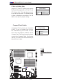
Expansion Slots
Three PCI-E 2.0 x8 slots (Slot 1/Slot 3/Slot7)•
Two PCI-E 2.0 x16 slots (Slot 2/Slot 6)•
One PCI-E 2.0 x4 (in x8) slots (Slot 5)•
One PCI-E 2.0 x8 (in x16) slots (Slot 4)•
BIOS
32 Mb AMI SPI Flash ROM•
PCI 2.2, ACPI 1.0/2.0/3.0, Plug and Play (PnP), DMI 2.3, USB Keyboard sup-•
port, and SMBIOS 2.3
PC Health Monitoring
Onboard voltage monitors for CPU0 Vcore, CPU1 Vcore, 1.5V, 5V, 5VSB, 12V, •
-12V, 3.3Vcc, 3.3VSB, VBAT and Vtt
Fan status monitor with fi rmware control
•
CPU/chassis temperature monitors•
Platform Environment Control Interface (PECI) ready•
Thermal Monitor 2 (TM2) support•
CPU fan auto-off in sleep mode•
CPU slow-down on temperature overheat•
Pulse Width Modulation (PWM) Fan Control •
CPU thermal trip support for processor protection, power LED•
Power-up mode control for recovery from AC power loss•
Auto-switching voltage regulator for CPU cores•
System overheat/Fan Fail LED Indicator and control•
Chassis intrusion detection•

Chapter 1: Introduction
1-7
System resource alert via Supero Doctor III•
ACPI Features
Slow blinking LED for suspend state indicator•
Main switch override mechanism•
ACPI Power Management•
Keyboard Wakeup from Soft-off •
Onboard I/O
Intel ICH10R supports six SATA2 ports (with RAID0, RAID1, RAID10, RAID5 •
supported in the Windows OS Environment, and RAID0, RAID1, RAID10 for
Linux Platforms) (Note 1)
Intel 82576 Gigabit Ethernet controllers supports Giga-bit LAN1/2 ports
•
A PHY chip supports the Dedicated IPMI LAN (X8DAH+-F only) • (Note 2)
One VGA Port supported by the Winbond WPCM 450R BMC Controller
•
PS/2 mouse/keyboard ports, one COM port and one Serial header•
Up to ten USB 2.0 (Universal Serial Bus) (six Backpanel USB Ports, and four •
Front Panel/Front Accessible USB connections)
Super I/O: Winbond W83627DHG
•
ALC 8830 Audio Controller supports 7.1 HD Audio with Line-in, Line-out and •
Microphone, Backpanel Audio and CD connections
Two Internal1394 headers
•
One EIDE Ultra DMA/100 bus master interface supports UDMA Mode 5 and •
PIO Mode 4
IPMI 2.0 with full KVM support (X8DAH+-F only)
• (Note 2)
Other
Console redirection•
Onboard Fan Speed Control by Thermal Management via BIOS•
CD/Diskette Utilities
BIOS fl ash upgrade utility and device drivers•
Dimensions
Ext. ATX 13.68" (L) x 13.00" (W) (347.47 mm x 330.20 mm)•
Note 1: For more information on SATA HostRAID confi guration, please
refer to the Intel SATA HostRAID User's Guide posted on our website @
http://www.supermicro.com/support/manuals/.
Note 2: For more information on IPMI confi guration, please refer to the
Embedded IPMI User's Guide posted on our website @ http://www.super-
micro.com/support/manuals/.

1-8
X8DAH+/X8DAH+-F User's Manual
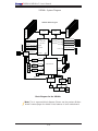
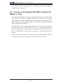
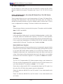
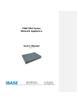
Block Diagram for the X8DAH+
Note: This is a general block diagram. Please see the previous Mother-
board Features pages for details on the features of each motherboard.
X8DAH+ System Diagram
PCI-E X16
CPU1
USB2.0
SATA2
Ports 3~6
PCI-E X4
PCIE X1
QPI
#0~9
Ports 1&2
SLOT#3
#0-4
#0-3
#0-2
#0-1
DDR3
#1-4
#1-3
#1-2
#1-1
800/1066/1333
800/1066/1333
DDR3
ESI X4
#1-5
#1-6
#0-5
#0-6
QPI
QPI
SLOT#2
PCI-E X8
SLOT#1
SLOT#4
PCI-E X8
PCI-E X16
PCI-E X8
PCI-E X8
QPI
SLOT#7
SLOT#6
SLOT#5
PCI-E X4
PCI-E X8
PCI-E X8
PCI-E X8
PCI-E X16
PCI-E X8
PCI-E X16
PCI-E X16
ESI
Ports7&8
Ports 9&10
Ports 3&4
Ports 5&6
Ports 7~10
IDE
PCI 33MHZ
SIO
LPC BUS
FLOPPY
6 REAR+4 FRONT
6 FRONT
RMII
LAN1
LAN2
SPI
WPCM150
INTEL
82576
#0-7
#0-8
#0-9
#1-7
#1-8
#1-9
Ports 1&2
PCI 33MHz
HD
AUDIO
HDR1
HDR2
External
VGA
COM2
KB
MS
BIOS
CPU2
#0~5
Intel ICH1OR
Intel 5520
Intel 5520
X8DAH+ Block Diagram
IDE
CTRL
1394
CTRL
Audio
CTRL
(IOH 36D)
(IOH 36D)
COM1
Internal
BMC
W83627DHG

Chapter 1: Introduction
1-9
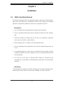
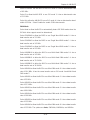
X8DAH+-F System Diagram
Block Diagram for the X8DAH+-F
Note: This is a general block diagram. Please see the previous Mother-
board Features pages for details on the features of each motherboard.
PCI-E X16
CPU1
USB2.0
SATA2
Ports 3~6
PCI-E X4
PCIE X1
QPI
#0~9
Ports 1&2
SLOT#3
#0-4
#0-3
#0-2
#0-1
DDR3
#1-4
#1-3
#1-2
#1-1
800/1066/1333
800/1066/1333
DDR3
ESI X4
#1-5
#1-6
#0-5
#0-6
QPI
QPI
SLOT#2
PCI-E X8
SLOT#1
SLOT#4
PCI-E X8
PCI-E X16
PCI-E X8
PCI-E X8
QPI
SLOT#7
SLOT#6
SLOT#5
PCI-E X4
PCI-E X8
PCI-E X8
PCI-E X8
PCI-E X16
PCI-E X8
PCI-E X16
PCI-E X16
ESI
Ports7&8
Ports 9&10
Ports 3&4
Ports 5&6
Ports 7~10
IDE
USB
PCI 33MHZ
SIO
LPC BUS
FLOPPY
6 REAR+4 FRONT
6 FRONT
RMII
LAN1
LAN2
SPI
WPCM450
INTEL
82576
#0-7
#0-8
#0-9
#1-7
#1-8
#1-9
Ports 1&2
PCI 33MHz
HD
AUDIO
HDR1
HDR2
External
VGA
COM2
KB
RMII
3rd LAN
LAN3
DDR II
MS
BIOS
CPU2
#0~5
Intel ICH1OR
Intel 5520
Intel 5520
X8DAH+ -F Block Diagram
IDE
CTRL
1394
CTRL
Audio
CTRL
(IOH 36D)
(IOH 36D)
COM1
Internal
BMC
W83627DHG

1-10
X8DAH+/X8DAH+-F User's Manual
1-2 Chipset Overview
Built upon the functionality and the capability of the 5500/5600 Series Processor
platform, the X8DAH+/X8DAH+-F motherboard provides the performance and
feature set required for dual-processor/IOH-based high-end systems optimized for
High Performance Computing (HPC)/Cluster platforms. The 5520 chipset consists
of the IOH 36D (I/O Hub), and the ICH10R (South Bridge). With the Intel QuickPath
Interconnect (QPI) controller built in, the 5520 platform offers the next generation
point-to-point system interconnect interface that replaces the current Front Side
Bus Technology, substantially enhancing system performance and scalability.
The IOH-36D connects to each processor through an independent QPI link. Each
link consists of 20 pairs of unidirectional differential lanes for transmission and
receiving in addition to a differential forwarded clock. A full-width QPI link pair
provides 84 signals.
The 5520 chipset supports up to 36 PCI Express Gen2 lanes, peer-to-peer read
and write transactions. The ICH10R provides up to seven PCI-Express ports, six
SATA ports and 10 USB connections.
In addition, the 5520 platform also offers a wide range of RAS (Reliability, Avail-
ability and Serviceability) features. These features include memory interface ECC,
x4/x8 Single Device Data Correction (SDDC), Cyclic Redundancy Check (CRC),
parity protection, out-of-band register access via SMBus, memory mirroring,
memory sparing, and Hot-plug support on the PCI-Express Interface.
Features of the 5500/5600 Processor and the 5520 Chipset
Four processor cores in each processor with 8MB shared cache among cores•
Two full-width Intel QPI links, up to 6.4 GT/s of data transfer rate in each direc-•
tion
Virtualization Technology, Integrated Management Engine supported
•
Point-to-point cache coherent interconnect, Fast/narrow unidirectional links, and •
Concurrent bi-directional traffi c
Error detection via CRC and Error correction via Link level retry
•

Chapter 1: Introduction
1-11
1-3 Special Features
Recovery from AC Power Loss
BIOS provides a setting for you to determine how the system will respond when
AC power is lost and then restored to the system. You can choose for the system
to remain powered off (in which case you must hit the power switch to turn it back
on) or for it to automatically return to a power- on state. See the Advanced BIOS
Setup section to change this setting. The default setting is Last State.
1-4 PC Health Monitoring
This section describes the PC health monitoring features of the X8DAH+/X8DAH+-F.
All have an onboard System Hardware Monitor chip that supports PC health moni-
toring. An onboard voltage monitor will scan these onboard voltages continuously:
CPU0 Vcore, CPU1 Vcore, 1.5V, 5V, 5VSB, 12V, -12V, 3.3Vcc, 3.3VSB, VBAT and
Vtt. Once a voltage becomes unstable, a warning is given or an error message is
sent to the screen. The user can adjust the voltage thresholds to defi ne the sensi-
tivity of the voltage monitor.
Fan Status Monitor with Firmware Control
The PC health monitor can check the RPM status of the cooling fans. The onboard
CPU and chassis fans are controlled by Thermal Management via BIOS (under
Hardware Monitoring in the Advanced Setting).
Environmental Temperature Control
The thermal control sensor monitors the CPU temperature in real time and will turn
on the thermal control fan whenever the CPU temperature exceeds a user-defi ned
threshold. The overheat circuitry runs independently from the CPU. Once it detects
that the CPU temperature is too high, it will automatically turn on the thermal fan
control to prevent any overheat damage to the CPU. The onboard chassis thermal
circuitry can monitor the overall system temperature and alert users when the chas-
sis temperature is too high.
Note: To prevent system overheating, be sure to provide adequate airfl ow
to the system.
CPU Fan Auto-Off in Sleep Mode
The CPU fan becomes active when the power is turned on. It continues to operate
when the system enters the Standby mode. When in the sleep mode, the CPU will
not run at full power, thereby generating less heat.

1-12
X8DAH+/X8DAH+-F User's Manual
System Resource Alert
This feature is available when used with Supero Doctor III in the Windows OS
environment or used with Supero Doctor II in Linux. Supero Doctor is used to
notify the user of certain system events. For example, you can also confi gure
Supero Doctor to provide you with warnings when the system temperature, CPU
temperatures, voltages and fan speeds go beyond a pre-defi ned range.
1-5 ACPI Features
ACPI stands for Advanced Confi guration and Power Interface. The ACPI specifi ca-
tion defi nes a fl exible and abstract hardware interface that provides a standard
way to integrate power management features throughout a PC system, including
its hardware, operating system and application software. This enables the system
to automatically turn on and off peripherals such as CD-ROMs, network cards, hard
disk drives and printers.
In addition to enabling operating system-directed power management, ACPI
provides a generic system event mechanism for Plug and Play and an operating
system-independent interface for confi guration control. ACPI leverages the Plug
and Play BIOS data structures while providing a processor architecture-independent
implementation that is compatible with both Windows 2000 and Windows 2003
Operating Systems.
Slow Blinking LED for Suspend-State Indicator
When the CPU goes into a suspend state, the chassis power LED will start blinking
to indicate that the CPU is in suspend mode. When the user presses any key, the
CPU will wake-up and the LED will automatically stop blinking and remain on.
Main Switch Override Mechanism
When an ATX power supply is used, the power button can function as a system
suspend button to make the system enter a SoftOff state. The monitor will be
suspended and the hard drive will spin down. Pressing the power button again
will cause the whole system to wake-up. During the SoftOff state, the ATX power
supply provides power to keep the required circuitry in the system "alive." In case
the system malfunctions and you want to turn off the power, just press and hold
the power button for 4 seconds. This option can be set in the Power section of
the BIOS Setup routine.
Page is loading ...
Page is loading ...
Page is loading ...
Page is loading ...
Page is loading ...
Page is loading ...
Page is loading ...
Page is loading ...
Page is loading ...
Page is loading ...
Page is loading ...
Page is loading ...
Page is loading ...
Page is loading ...
Page is loading ...
Page is loading ...
Page is loading ...
Page is loading ...
Page is loading ...
Page is loading ...
Page is loading ...
Page is loading ...
Page is loading ...
Page is loading ...
Page is loading ...
Page is loading ...
Page is loading ...
Page is loading ...
Page is loading ...
Page is loading ...
Page is loading ...
Page is loading ...
Page is loading ...
Page is loading ...
Page is loading ...
Page is loading ...
Page is loading ...
Page is loading ...
Page is loading ...
Page is loading ...
Page is loading ...
Page is loading ...
Page is loading ...
Page is loading ...
Page is loading ...
Page is loading ...
Page is loading ...
Page is loading ...
Page is loading ...
Page is loading ...
Page is loading ...
Page is loading ...
Page is loading ...
Page is loading ...
Page is loading ...
Page is loading ...
Page is loading ...
Page is loading ...
Page is loading ...
Page is loading ...
Page is loading ...
Page is loading ...
Page is loading ...
Page is loading ...
Page is loading ...
Page is loading ...
Page is loading ...
Page is loading ...
Page is loading ...
Page is loading ...
Page is loading ...
Page is loading ...
Page is loading ...
Page is loading ...
Page is loading ...
Page is loading ...
Page is loading ...
Page is loading ...
Page is loading ...
Page is loading ...
Page is loading ...
Page is loading ...
Page is loading ...
-
 1
1
-
 2
2
-
 3
3
-
 4
4
-
 5
5
-
 6
6
-
 7
7
-
 8
8
-
 9
9
-
 10
10
-
 11
11
-
 12
12
-
 13
13
-
 14
14
-
 15
15
-
 16
16
-
 17
17
-
 18
18
-
 19
19
-
 20
20
-
 21
21
-
 22
22
-
 23
23
-
 24
24
-
 25
25
-
 26
26
-
 27
27
-
 28
28
-
 29
29
-
 30
30
-
 31
31
-
 32
32
-
 33
33
-
 34
34
-
 35
35
-
 36
36
-
 37
37
-
 38
38
-
 39
39
-
 40
40
-
 41
41
-
 42
42
-
 43
43
-
 44
44
-
 45
45
-
 46
46
-
 47
47
-
 48
48
-
 49
49
-
 50
50
-
 51
51
-
 52
52
-
 53
53
-
 54
54
-
 55
55
-
 56
56
-
 57
57
-
 58
58
-
 59
59
-
 60
60
-
 61
61
-
 62
62
-
 63
63
-
 64
64
-
 65
65
-
 66
66
-
 67
67
-
 68
68
-
 69
69
-
 70
70
-
 71
71
-
 72
72
-
 73
73
-
 74
74
-
 75
75
-
 76
76
-
 77
77
-
 78
78
-
 79
79
-
 80
80
-
 81
81
-
 82
82
-
 83
83
-
 84
84
-
 85
85
-
 86
86
-
 87
87
-
 88
88
-
 89
89
-
 90
90
-
 91
91
-
 92
92
-
 93
93
-
 94
94
-
 95
95
-
 96
96
-
 97
97
-
 98
98
-
 99
99
-
 100
100
-
 101
101
-
 102
102
-
 103
103


Supermicro Supero X8DAH+ User manual
- Category
- Motherboards
- Type
- User manual
Ask a question and I''ll find the answer in the document
Finding information in a document is now easier with AI
Related papers
-
Supermicro MBD-X8DAH+-F-O User manual
-
Supermicro Supero X8DAH+-F-LR User manual
-
SUPER MICRO Computer X8DAH+-F-LR User manual
-
-
-
-
-
Supermicro X8DTN+-F User manual
-
-
Other documents
-
 RadiSys PROCELERANT SB5520DT1-SAS User manual
-
Gigabyte GA-6UASL3 User manual
-
Gigabyte GA-3CESL3-RH User manual
-
-
Gigabyte GA-7TESM1 User manual
-
-
-
 Supero Supero Embedded BMC/IPMI User manual
-
 IBASE Technology IB798 User manual
-
Quantum NDX Series User manual


