
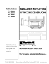
Models/Modelos
721.62622
721.62624
721.62629
721.62642
721.62643
721.62644
721.62649
Read and save these
installation instructions.
Lea y guarde estas
instrucciones de
instalaci6n
INSTALLATIONINSTRUCTIONS
INSTRUCCIONESDEINSTALACION
®
MicrowaveHoodCombination
Combinaci6nMicroondasCampana
0
I"
PartNo. 3828W5U0279 Sears, Roebuck and Co., Hoffman Estates,IL.60179 U.S.A www.sears.com.

YOUR SAFETY FIRST
BEFORE YOU START
• Proper installation is the installer's responsibility!
- Read the entire manual before you begin.
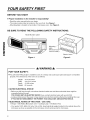
- The model number label is located on the oven front. See Figure 1.
- Mounting plate is located on back side of microwave oven. See Figure 2.
BE SURE TO READ THE FOLLOWING SAFETY INSTRUCTIONS:
Model Number Label
63
r-
Mounting
plate
(Remove fron
oven to install.)
Back of oven
Figure 1 Figure 2
A WARNING A
FOR YOUR SAFETY:
• You will need TWO people to install this oven. It is heavy and could cause personal injury if not handled
properly. The dimensions of the oven are as follows:
Height : 16-7/16 inches
Width : 29-15/16 inches
Depth : 15-3/8 inches
Weight : 52 pounds
• AVOID ELECTRICAL SHOCK!
- Before you drill into the wall, note where electrical outlets are and where electrical wires might be
concealed behind the wall.
YOU COULD GET AN ELECTRIC SHOCK it you contact electrical wires with your drill bit.
- Locate and disconnect the power of any electrical circuits that could be affected by installing this oven.
IF YOU DO NOT DISCONNECT THE POWER, YOU COULD GET AN ELECTRIC SHOCK.
• ELECTRICAL RATING OF THIS OVEN : 120V, 60Hz.
14 Amps / 1500 Watts (Microwave oven + Cooktop Lamp + Ventilation Fan)
- You need a 120V, 60Hz, AC only, 15A or 20A, fused electrical supply (located in the cabinet above the
microwave as close as possible to the microwave circuit) serving only the microwave.
2

YOUR SAFETY FIRST
• THIS APPLIANCE MUST BE GROUNDED!
- If there is an electrical short circuit, grounding reduces the risk of electrical shock by providing an escape
wire for the electric current. This appliance is equipped with a cord having a grounding wire with a
grounding plug.
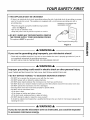
• Place the plug into a properly installed and grounded
outlet. See Figure 3.
• Do not use an extension cord.
• Keep the power cord dry and do not pinch or crush it.
• DO NOT, UNDER ANY CIRCUMSTANCES, REMOVE
THE POWER SUPPLY CORD GROUNDING PRONG!
This appliance MUST be grounded!
PROPERLY POLARIZED AND
GROUNDED OUTLET
Three-Pronged (Grounding) plug
Figure 3
A WARNING A
If you use the grounding plug improperly, you risk electric shock!
- Check with a qualified electrician if you are not sure whether the oven is properly grounded or if you do
not completely understand the grounding instructions.
DO NOT USE A FUSE IN THE NEUTRAL OR GROUNDING CIRCUIT.
I'll
Z
i=
m
01
A WARNING A
Improper grounding could result in electric shock or other personal injury.
SAVE THESE INSTRUCTIONS FOR THE LOCAL ELECTRICAL INSPECTOR'S USE.
• DO NOT EXPOSE YOURSELF TO EXCESSIVE MICROWAVE ENERGY!
- DO NOT try to operate the microwave oven with the door open.
- DO NOT tamper with or defeat the safety interlocks.
- DO NOT place objects between the microwave oven front face and the door.
- DO NOT allow soil or cleaner residue to build up on the flat surfaces around the microwave oven door.
- DO NOT operate the microwave oven if it is damaged.
- The microwave oven door must close properly to operate safely.
- DO NOT use the microwave oven:
• If the door is bent.
• If the hinges or latches are broken or loose.
• If the door seals, sealing surfaces or glass is broken.
- DO NOT attempt to adjust or repair the oven yourself!
It should be adjusted and repaired by a qualified technician who can check for microwave leakage after
repairing the oven.
A WARNING A
If you do not use the microwave oven as instructed, you could be exposed
to excessive microwave energy.

YOUR SAFETY FIRST
• MAKE SURE YOU HAVE ENOUGH SPACE AND SUPPORT.
- Mount the oven against a flat, vertical wall, so that it is supported by the wall. The wall should be
constructed of minimum 2" x 4" wood studding and 3/8" thick drywall or plaster/lath.
- ATTACH AT LEAST ONE of the two lag screws supporting the oven to a vertical, 2" x 4" wall stud.
- DO NOT mount the microwave oven to an island or peninsula cabinet.
- BE SURE the upper cabinet and rear wall structures are able to support 150 Ibs., plus the weight of any
items you place inside the oven or upper cabinet.
- Locate the oven away from strong draft areas, such as windows, doors, and strong heating vents.
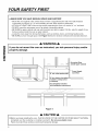
- BE SURE you have enough space. See Figure 4 below for minimum vertical and horizontal clearance.
r-
A WARNING A
If you do not mount the oven as instructed, you risk personal injury and/or
property damage.
30" min. cabinet openingwidth'
30" rain. clearancefrom bottom
of cabinetto cookingsurface
or countertop
(Use templates included
with installation instructions)
/Grounded Plug
(inside upper cabinet)
Power Supply
Cord Hole
Figure 4
CAUTION A
• Before you begin installing the oven, PLACE A PIECE OF THE CARTON OR OTHER HEAVY MATERIAL
(a blanket) over the countertop or cooktop to protect it. Do not use a plastic cover.
Failure to protect these surfaces could result inproperty damage.
4

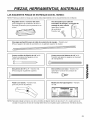
PARTS, TOOLS, MATERIALS
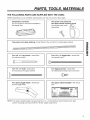
THE FOLLOWING PARTS ARE SUPPLIED WITH THE OVEN:
NOTE: Depending on your ventilation requirements, you may not use all of these parts.
Damper/duct connector
(for roof vented or wall vented installation)
Not Actual Size
One power cord clamp and
One dark-colored mounting screw
(to hold the power cord)
Actual Size
One power cord clamp bushing - Actual Size (for the cord hole in a metal upper cabinet)
Four 114" x 2" lag screws - Actual Size
(for wall stud holes)
Four 114" x 3" toggle bolts - Actual Size
(for drywall holes)
I11
Z
I=
m
01
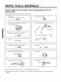
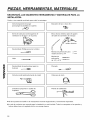
Two 1/4" x 3" bolts - Actual Size
(for securing to the upper cabinet)
Two tapping screws - Actual Size
(for attaching the damper duct connector)
Four spring toggle heads - Actual Size
(for the toggle bolts)
One upper cabinet template - Not Actual
Size
NOTE: You need to install at least one lag screw into a 2" x 4" stud and four anchor bolts into the wall,
and the mounting area must meet the 150 Ibs. weight requirement.
5

PARTS, TOOLS, MATERIALS
YOU WILL NEED THE FOLLOWING TOOLS AND MATERIALS FOR THE
INSTALLATION:
Carton or other heavy material for covering the counter top.
Clear tape
(for taping the templates to the wall)
Stud finder or thin nail.
Saber saw (for cutting vent holes for roof
or wall venting)
Phillips screwdriver (for the screws)
Pencil
I
Key hole saw (for the power cord hole)
3/8" and 3/4" wood drill bits ._
1/2" and 3/16"
drill bits
Flat blade screwdriver (for the bolts)
Plumb line
Duct TapeMeasuring tape (metal preferred)
Small side cutters or tin snips Caulking gun
• If you have brick or masonry walls, you need special hardware and tools.
• The ductwork you need for the installation is not included. All wall and roof caps must have a back-draft
damper.
6

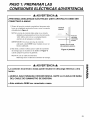
STEP 1: PREPARE THE
ELECTRICAL CONNECTIONS
A WARNING A
AVOID ELECTRICAL SHOCK! THIS APPLIANCE MUST BE GROUNDED!
1. Locate the grounded electric outlet for this oven in the
cabinet above the oven, as shown in Figure 4 Detail.
NOTE: The outlet should be on a circuit dedicated to the
microwave oven 120V, 60Hz., AC only, with a
20ampere fused electrical supply.
IMPORTANT: Ifyou do not have the proper wall outlet,
you MUST have one installed by a qualified
electrician.
2. You will cut the power-supply-cord hole (shown in
Figure 4 Detail) later when you prepare the wall and
upper cabinet in Step 4.
NOTE: Do not use an extension cord.
Keep the power cord dry and do not pinch or crush it.
Upper I
Cabinet _
.............................................'%.
f
Grounded Outlet
Q
[
Power-Supply-CordHole
Figure 4 Detail
m
Z
I"
m
A WARNING A
Improper grounding could result in electric shock or other personal injury.
• DO NOT, UNDER ANY CIRCUMSTANCES, REMOVE THE POWER SUPPLY
CORD GROUNDING PRONG!
• This appliance MUST be grounded!

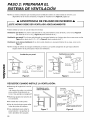
STEP 2:
PREPARE THE VENTING SYSTEM
NOTE: The ductwork you need for outside ventilation is not included with your oven. The standard ductwork
fittings and length are shown in Figure 9, page 9.
WARNING - FIRE HAZARD
THIS OVEN MUST BE PROPERLY VENTED!
J
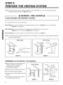
You may vent your oven in one of three ways:
Roof Venting If your oven is located on an outside wall near the roof, as in Figure 6 (3-1/4" x 10" duct) and
Figure 8 (6" round duct.)
Wall Venting If your oven is located on an outside wall on the first floor of your house, as in
Figure 5 (3-1/4" x 10" duct) and Figure 8 (6" round duct.)
Room Venting If your oven is located on an inside wall of your house, as in Figure 7.
NOTE: If you choose the rear exhaust method (roof or wall venting), be sure there is enough clearance within the
wall for the exhaust duct.
Wall Venting
cabinet__
wa,,ca
oven _ulc/4"x10" through-the-wall
Wallventing
Figure 5
cabinet
Roof venting
Roof Venting
duct _]
through-the-roof
Figure 6
REMEMBER AS YOU INSTALL THE VENTING:
• Keep the length of the ductwork and the
number of elbows to a minimum to
ventilate your oven efficiently.
See examples on page 9.
• Keep the size of the ductwork the same.
• Do not install two elbows together.
• Use duct tape to seal all joints in the duct
system.
• Use caulking to seal the exterior wall or
roof opening around the cap.
Room Venting
cabine_
ovei
Figure 7
roof cap
6" min.
diameter
round
elbow
3-1/4"to round
ducttransition
wall cap
3-1/4"to round
ductworktransition
Figure 8
8

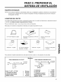
STEP 2:
PREPARE THE VENTING SYSTEM
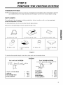
STANDARD FITTINGS
NOTE: If the existing duct is round, you must use a rectangular-to-round adapter, with a rectangular 3" extension
duct installed between the damper assembly and the adapter to prevent the exhaust damper sticking.
DUCT LENGTH
The total length of the duct system, including straight duct, elbows, transitions, wall or roof caps must not
exceed the equivalent of 140 feet.
For best performance, do not use more than three 90 degree elbows.
Below are the standard fittings and their equivalent length in feet.
3-1/4"x10" to 6" = 5ft.
90° elbow = lOft.
3-1/4"x10" roof cap = 24ft.
3-1/4"xl 0" wall cap
= 40ft.
45 °elbow = 5ft.
3-1/4"x10" 90° elbow = 25ft.
3-1/4"xl 0" flat elbow
= 1Oft.
I11
Z
61
i=
m
Figure 9
To calculate the equivalent length of each duct piece used, see the examples below.
I
Examples
For 3-1/4"x10" SYSTEMS
3-1/4"x10" _ 6ft. -._1 _2 wall cap
90° elbow ,,_]_
U
2ft.
1 3-1/4" x 10" 90 °elbow = 25 ft.
1 wall cap = 40 ft.
8 feet straight duct - 8 ft.
TOTAL LENGTH - 73 ft.
For 6" ROUND SYSTEMS
wall cap
90° elbows _--- 6ft. ,_[_/
transi_
1 transition = 5 ft.
2 90 °elbows = 20 ft.
1 wall cap = 40 ft.
8 feet straight - 8 ft.
TOTAL LENGTH - 73 ft.

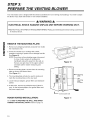
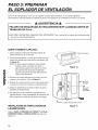
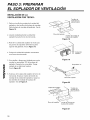
STEP 3:
PREPARE THE VENTING BLOWER
Your microwave oven is shipped with the blower assembled for room venting (recirculating). You need to adjust
the blower if you want wall vented or roof vented installation.
A WARNING A
ELECTRICAL SHOCK HAZARD! UNPLUG UNIT BEFORE WORKING ON IT.
• DO NOT PULL OR STRETCH THE BLOWER WIRING! Pulling and stretching the blower wiring could result
in electrical shock.
¢1
r-
O1
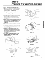
REMOVE THE MOUNTING PLATE:
1. Remove any shipping materials and parts from inside
the microwave oven.
2. Cover the counter top or cooktop with a thick,
protective covering to protect it from damage and dirt.
See Figure 10.
NOTE: If you have a free-standing range, disconnect
it, move it onto a piece of cardboard or
hardboard and pull it away from the wall, so
that you can get closer to the upper cabinet
and back wall for easier measuring and
drilling.
3. Remove mounting plate 2 screws from the mounting
plate as shown and discard them.
(See Figure 11.)
4. The mounting plate will also be used to locate and
mark the mounting holes on the rear wall.
5. Locate exhaust adaptor, grease filters and hardware
packet.
6. At this point, remove any adhesive tape (if there is
any), on the exhaust adaptor, the grease filters and
the power supply cord.
ROOM VENTED INSTALLATION:
Go to STEP 4, PREPARE THE WALL AND UPPER
CABINET FOR INSTALLATION located on page 13.
A thicK,protective
ring
Figure 10
j o°
!
L Control panel side
Mounting
plate
Mounting
Plate
screws
Figure 11
10

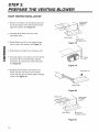
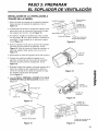
STEP 3:
PREPARE THE VENTING BLOWER
WALL VENTED INSTALLATION:
1. Remove one blower unit mounting screw and
two blower plate screws. Remove the blower
plate from cabinet. See Figure 12.
2. Carefully lift the blower unit out of the microwave
oven. Disconnect the blower wire from
connector. See Figure 13.
3. Use side cutters or tin snips to cut and remove
knockouts "B" from Back plate. Discard
knockouts. Be careful not to distort the plate.
See Figure 14.
4. Rotate the unit so that the exhaust ports face the
rear of the cabinet. See Figure 15. Before you
insert blower unit, blower wire must be like
Figure 15.
5. Reassemble the blower wire into the connector.
6. Place blower unit back into cabinet. Check that
the exhaust ports face towards the rear of the
cabinet. See Figure 16.
7. Reattach the blower plate to the top of the
cabinet as it was originally assembled. Attach
with one blower unit mounting screw and then
two blower plate mounting screws.
See Figure 17.
8. Go to STEP 4, PREPARE THE WALL AND
UPPER CABINET FOR INSTALLATION
located on page 13.
Figure 14
exhaust
ports
Figure 16
blower unit
back plate
plate
mounting screws
Knockouts "B"
blower plate -o<_...
blower unit
mounting screw
Figure 12
_blower wire
Figure 13
blower
unit
exhaust
ports
Figure 15
blower plate
mounting
s_rews
blower unit
mounting screw
Figure 17
I11
Z
I"
m
01
11

STEP 3:
PREPARE THE VENTING BLOWER
ROOF VENTED INSTALLATION"
01
1. Remove one blower unit mounting screw and
two blower plate screws. Remove the blower
plate from cabinet. See Figure 18.
2. Carefully lift the blower unit out of the
microwave oven.
3. Rotate blower unit 90° so the exhaust ports
face the top of the cabinet. See Figure 19.
4. Place blower unit back into microwave oven.
5. Use side cutters or tin snips to cut and remove
knockouts "A" from blower plate. Discard
knockouts. Be careful not to distort the plate.
See Figure 20.
6. Reattach blower plate to microwave oven.
Attach with the one blower unit mounting
screw and then the two blower plate mounting
screws. See Figure 21.
blower plate
smc_UnJ_ng
blower plate -o_
blowerunit
mounting screw
Figure 18
blower
unit
Figure 19
Knockouts "A"
blower plate
Figure 20
blowerunit _ _ blower plate
__ _ mounJ_ng
blower plate blower unit
mounting screws
Figure 21
12

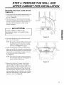
STEP 4: PREPARE THE WALL AND
UPPER CABINET FOR INSTALLATION
MEASURE AND TACK/TAPE UP THE
TEMPLATE
1. Using a plumb line and (metal) measuring tape, find
and mark the vertical center line (_) on the back
wall, as in Figure 22.
2. Find and mark one or two points where the studs
are on the wall (Studs are normally 16 inches apart.)
and then measure and mark the stud locations. If
you cannot find any wall stud, consult a local
building contractor.
A CAUTION A
DO NOT ATTEMPT TO INSTALL THE
MICROWAVE OVEN IF YOU CANNOT FIND A
WALL STUD.
3. Line up the plumb line on the wall with the center
line on the mounting plate.
NOTE: Be sure the minimum width is 30 inches and
the distance from the top of the mounting
plate to the range or counter top is at least
30 inches. See Figure 4 on page 4.
4. Center mounting plate in opening by lining up the
plumb line on wall with centerline on mounting plate.
Make sure the minimum width is 30 inches and that
the top of the mounting plate is located a minimum
of 30 inches above the cooking surface.
See Figure 23.
NOTE: If the front edge of the cabinet is lower than
the back edge, adjust the mounting plate to
be level with the cabinet front.
5. Measure the bottom of the upper cabinet frame.
Trim the edges "A", "B" and "C" on the upper
cabinet template so that the template will fit on the
bottom of the upper cabinet. If upper cabinet has a
recessed frame, trim template so that it fits inside
the recessed area. Align the centerline of the upper
cabinet template with the centerline of the mounting
plate; then securely tape or tack the upper cabinet
template in place. See Figure 23.
©
/
Figure 22
© ©
Figure 23
I"
m
(/}
©
13

STEP 4: PREPARE THE WALL AND
UPPER CABINET FOR INSTALLATION
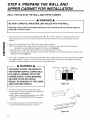
DRILL THE HOLES IN THE WALL AND UPPER CABINET.
WARNING
BE VERY CAREFUL WHEN DRILLING HOLES INTO THE WALL.
Electrical wires could be concealed behind the wall covering and if the drill hits them you
could get an electric shock.
01
1. Find the points on the mounting plate labeled "A", "B", "C" and "D". Drill a 3/16" diameter hole at any of
these points that are in front of a wall stud. Drill a 3/4" diameter hole at any of these points that are over
drywall.
2.
Drill a 3/8" hole at points "J" and "K" on the upper cabinet template.
NOTE: If the bottom of the upper cabinet is recessed 3/4" or more, you will need 2"x2" filler blocks (not
included) to provide additional support for the bolts. See Figure 24.
• Mark the center of each filler block and drill a 3/8" diameter hole at the mark.
• Align filler blocks over the two openings in the top of the microwave oven cabinet and attach to cabinet with
masking tape. See Figure 25.
3. Cut or drill a 2" diameter hole at the area marked "M", "power supply cord hole" on the upper cabinet template.
Ifthe upper cabinet is metal, you will need to cover the edge of the hole with the power supply cord bushing
(supplied) to prevent damage to the cord from the rough metal edge.
WARNING
YOU MUST COVER THE EDGE OF
THE POWER SUPPLY CORD HOLE
IN A METAL CABINET WITH THE
POWER SUPPLY CORD BUSHING.
FAILURE TO DO SO COULD
RESULT IN DAMAGE TO THE CORD
AND ELECTRIC SHOCK.
cabinet front filler block
Figure 24
cabinet
bottom shelf
4. Cut out the venting areas (with the saber saw):
• Roof Venting: cut out the shaded area marked "L"
on the upper cabinet template.
• Wall or Room Venting (Recirculating): go to STEP
5, INSTALL THE MOUNTING PLATE, located on
page 15.
5. Use caulking compound to seal the exterior wall or
roof opening around the wall cap or roof cap.
Figure 25
14

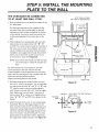
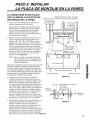
STEP 5: INSTALL THE MOUNTING
PLATE TO THE WALL
THE OVEN MUST BE CONNECTED
TO AT LEAST ONE WALL STUD.
1. Draw a vertical line on the wall at the center of the
30" wide space.
Use the mounting plate as the template for the
rear wall. Place the mounting plate on the wall,
making sure that the tabs are against the bottom
of the cabinet. Line up the notch and center line
on the mounting plate to the center line on the
wall.
2. While holding the mounting plate with one hand,
draw circles on the wall at holes "A", "B", "C"
and "D". Four holes must be used for mounting. If
the holes are not used, the installation will not be
secure. Installer must use these holes for proper
installation. Use toggle bolts through these holes
unless one of them lines up with a stud. Use a
wood screw for studs. See Figure 26.
NOTE: Draw a fifth circle inside area "E", through
one of the holes to match the location of a
stud.
For wall vented: The oven requires a rear wall
cutout opening for the rear wall duct and the
exhaust adaptor must be attached to the mounting
plate. See the next page on how to prepare the rear
wall cutout opening and the exhaust
adaptor/mounting plate for wall vented.
3. Drill holes through the circles. If there is a stud,
drill a 3/16" hole for lag screws. Two or preferably
four lag screws at holes "A" and "C", or "B" and
"C" must be used to secure mounting plate to
wall. If there is no stud, drill a 3/4" hole for toggle
bolts. Make sure to use at least 1 lag screw at
holes of area "E" in a stud, and 4 toggle bolts at
holes "A", "B", "C" and "D" in the drywall or the
plaster.
4. Attach the plate to the wall. To use spring toggle
head bolts: Remove the toggle wings from the
bolts. Insert the bolts into the mounting plate and
replace the spring toggle heads to 3/4" past the
bolt ends. Insert the spring toggle heads into the
holes in the wall to mount the bracket. You may
pull forward on the bracket to help in tightening
the toggle bolts. Tighten all bolts. See Figure 27.
3/16" Hole on Studs
3/4" Hole on Drywall Only
I FMrinirn_l_266'°r II '
L I ii F°rWall
• Vented O_ly
' / Draw Lines _ ,
, on Studs
' Mounting _
I
/ Plate _ Draw _
n i
/ / | Center Line _ '
° ..........
o
C_ ] CenterLine -_"
o OoOoO o ooocooo ° coooooco o ocooo o
t ' [] ' t
Support Tab Support Tab
m
Figure 26
Space More Than Wall Thickness
Mounting I T( jgle Wings
Plate
Bolt
End
Figure 27
I11
Z
i=
I
01
Z
15

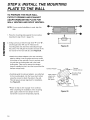
STEP 5: INSTALL THE MOUNTING
PLATE TO THE WALL
TO PREPARE THE REAR WALL
CUTOUT OPENING AND EXHAUST
ADAPTOR/MOUNTING PLATE FOR
WALL VENTING AND ROOF VENTING:
NOTE: If room vented installation is used, skip this
step.
1. Place the mounting plate against the rear wall as
described in step 5 item 1 (page 15).
2. Using a pencil, put dots through slots "F" and "G",
and through holes "H" and "1". Remove the
mounting plate and draw lines extending through
the points. This will give the location and size of the
m_ box cutout for the rear wall duct. See Figure 28.
01
• Attach the exhaust adaptor to the rear mounting
plate by sliding it into the guides at the top center
of the plate on the wall side. Push in securely until
it is past the top locking tabs and in the lower
locking tabs. Take care to assure the damper
hinge is installed so that it is at the top and that the
damper swings freely.
• Carefully guide the exhaust adaptor, now attached
to the mounting plate, into the house duct, before
using the screws to attach the plate to the wall.
This will assure proper alignment for installation.
See Figure 29.
• Return to step 5, item 3 (page 15) to continue.
After completing the installation of the mounting
plate, again check the rear damper for free
movement to assure it will operate properly.
Exhaust Adaptor
Slide exhaust
adaptor into
guides on
rear panel.
Figure 28
Damper
(hinge side up)
Mounting Plate
(wall side)
Locking
Tabs
Guides
Figure 29
16

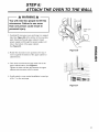
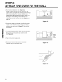
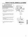
STEP 6:
A TTACH THE OVEN TO THE WALL
A WARNING A
You will need two people to lift this
microwave. Failure to use more
than one person could result in
personal injury.
1. Carefully lift microwave oven and hang it on support
tabs (See Figure 26) at the bottom of the mounting
plate. Reaching through upper cabinet, thread
power supply cord through the power supply cord
hole in the bottom of the upper cabinet.
See Figure 30.
2. Rotate the microwave oven upward so the top of
oven is against the bottom of the upper cabinet or
cabinet frame.
3. Then insert a bolt down through each hole in the
upper cabinet bottom. See Figure 31.
Tighten the bolts until the gap between the upper
cabinet and microwave oven is closed.
4. If wall vented or room vented installation is used, go
to No. 7 on the next page.
Figure 30
m
Z
I"
m
Figure 31
17

STEP 6:
ATTACH THE OVEN TO THE WALL
r-
5. Roof vented installation: See Figure 32.
Install ductwork through the vent opening in the
upper cabinet. Complete the venting system through
the roof according to the method needed. See
"PREPARE THE VENTING SYSTEM," STEP 2 on
the page 8. Use caulking to seal exterior roof
opening around the exhaust cap. See Figure 6 on
page 8.
6. Use power supply cord clamp to bundle the power
supply cord. Install the power supply cord clamp,
using a screw as shown in Figure 33, to inside of
the cabinet.
7. To install the grease filter: Slide it into the slide slot,
then push up and toward oven center to lock.
See Figure 34.
8. Plug in the power supply cord.
9. Read your Owner's Manual, then check the
operation of your microwave oven.
Figure 32
power
supply
cord
clamp
Figure 33
Figure 34
18

MEMO
19

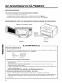
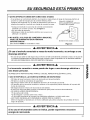
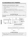
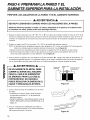
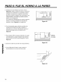
SU SEGURIDAD EST,4 PRIMERO
ANTES DE EMPEZAR
• iLa correcta instalacibn es responsabilidad del instalador!
- Lea el manual completo antes de empezar.
- La etiqueta con el nt_mero de modelo esta en el frente del horno. Vea la Figura 1.
- La placa de montura esta en la parte posterior del horno de microonda. Vea la Figura 2.
ASEGURESE DE LEER LAS SIGUIENTES INSTRUCCIONES DE SEGURIDAD:
Etiqueta con el nt_mero de modelo
Figura 1
Placa de
montura
(quitela del
horno para instalarlo)
Parte posterior
del horno
Figura 2
0
f-
ADVERTENCIA
PARA SU SEGURIDAD:
• Necesitara DOS personas para instalar este horno. Es pesado y si no se Io manipula correctamente, podria
causar lesiones. Las dimensiones del horno son las siguientes:
Alto : 16-7/16 pulg
Ancho : 29-15/16 pulg
Profundidad : 15-3/8 pulg
Peso : 52 libras
• iPREVENGA DESCARGAS ELI_CTRICAS!
- Antes de perforar la pared note donde podrian estar ocultos en la pared las posibles tomas de corriente y
cables el_ctricos.
SE EXPONE A UNA DESCARGA ELleCTRICA si la boca de barrena de su taladro el_ctrico hace
contacto con alguno de estos cables.
- Localice y desconecte la energia el_ctrica de cualquier circuito el_ctrico que podria verse afectado por la
instalaci6n de este horno.
Sl NO LOS DESCONECTA SE EXPONE A UNA DESCARGA ELleCTRICA.
• POTENCIA DE SERVICIO DE ESTE HORNO: 120V, 60Hz.
14 Amps / 1500 Wats (Horno de microondas + Lampara cocina + ventilador de extracci6n)
- Usted necesita solamente 120V, 60Hz, s61o CA, 15A o 20A, suministro el_ctrico con fusible (ubicado en
el gabinete sobre el microondas Io mas cerca posible del circuito de microondas) y que sirva s61o al
microondas.
20
Page is loading ...
Page is loading ...
Page is loading ...
Page is loading ...
Page is loading ...
Page is loading ...
Page is loading ...
Page is loading ...
Page is loading ...
Page is loading ...
Page is loading ...
Page is loading ...
Page is loading ...
Page is loading ...
Page is loading ...
Page is loading ...
Page is loading ...
-
 1
1
-
 2
2
-
 3
3
-
 4
4
-
 5
5
-
 6
6
-
 7
7
-
 8
8
-
 9
9
-
 10
10
-
 11
11
-
 12
12
-
 13
13
-
 14
14
-
 15
15
-
 16
16
-
 17
17
-
 18
18
-
 19
19
-
 20
20
-
 21
21
-
 22
22
-
 23
23
-
 24
24
-
 25
25
-
 26
26
-
 27
27
-
 28
28
-
 29
29
-
 30
30
-
 31
31
-
 32
32
-
 33
33
-
 34
34
-
 35
35
-
 36
36
-
 37
37


Kenmore 72162624200 Installation guide
- Type
- Installation guide
- This manual is also suitable for
Ask a question and I''ll find the answer in the document
Finding information in a document is now easier with AI
in other languages
Related papers
-
 Kenmore Elite 72180803400 Installation guide
-
Kenmore 72181622600 Installation guide
-
LG 85063 Installation guide
-
-
-
Kenmore 72180593402 Installation guide
-
LG 721.80002 Installation guide
-
LG 85023 Installation guide
-
Kenmore 721.62649 Installation guide
-
Sears 85062 Template

Other documents
-
Bosch HMV8050/01 Installation guide
-
LG LMV1611ST Installation guide
-
LG LMV1751ST Installation guide
-
LG 85053 Installation guide
-
-
-
-
-
-