Kenmore 119.166750 Owner's manual
- Category
- Barbecues & grills
- Type
- Owner's manual
This manual is also suitable for

OPERATOR'S MANUAL
Liquid Propane Gas (LPG) Grill
Model119.166750
Natural Gas (NG) Grill
Model119.176750
• Safety
• Assembly
• Use and Care
• Cooking Guide
• Frequently Asked Questions
Call us first if you have any problem with this
product. We can help you with questions about
assembly and grill operation or if there are
damaged or missing parts when you unpack this
unit from the carton. Please call before returning
to the store.
1-800-933-0527
8:30am-5:OOpm CST, Monday throuqh
• NOTE TO ASSEMBLER/INSTALLER:
Leave this manual with the consumer.
• NOTE TO CONSUMER:
Keep this manual for future reference.
• RECORD YOUR SERIAL#
(see silver CSA label on main body of grill)
• DATE OF PURCHASE:
ATFACH YOUR SALES RECEIPT HERE:
• Failure to comply with these instructions could
result in a fire or explosion that could cause
serious bodily injury, death or property damage.
• Whether this grill was assembled by you or
someone else, you must read this entire manual
before using your grill to ensure the grill is
properly assembled, installed and maintained.
• Use your grill at least 2 feet away from any
wall or surface. Use your grill at least 2 feet
away from combustible objects that can melt or
catch fire (such as vinyl or wood siding, fences
and overhangs) or sources of ignition including
pilot lights on water heaters and live electrical
appliances.
• THIS GAS APPLIANCE IS DESIGNED FOR
OUTDOOR USE ONLY.
• Combustion byproducts produced when using
this product contain chemicals known to the
State of California to cause cancer, birth
defects, or other reproductive harm.
Sears, Roebuck and Co., Hoffman Estates, IL 60179 U.S.A. www.sears.com

Primary Safety Warnings ........................... 1-3
Warranty Terms and Conditions ................... 2
Pre-Assembly Instructions ............................ 3
Part Diagram and Lists .............................. 4-9
Assembly Instructions ............................ 10-14
LP Gas Tank Instructions ...................... 15-17
Natural Gas Instructions ...................... 18-19
Use and Care Instructions ............................. 19-23
Cleaning and Maintenance ............................ 23-24
Cooking Guide .................................................. 25-26
Frequently Asked Questions .......................... 27-28
Sears Parts and Service Information ................29
Two-Year Full Warranty on Kenmore Elite
Grill
If this grill fails due to a defect in material or
workmanship within two years from the date of
purchase, call 1-800-4-MY-HOME® to arrange for
free repair (or replacement if repair proves
impossible).
Additional Limited Warranty on Specific
Grill Parts
After the second year from date of purchase for
the time periods listed below the following specific
grill parts will be supplied free of charge if they fail
due to defects in material or workmanship. You
will pay any labor charges if you wish to have
them installed.
• Stainless Steel Tube Burners - Unlimited
• Other Stainless Steel Parts - 3 years
Warranty Restrictions
All warranty coverage excludes igniter batteries,
grill paint loss, rusting or stainless steel
discoloration, which are either expendable parts
that can wear out from normal use in less than
two years, or are conditions that can be the result
of normal use, accident or improper maintenance.
All warranty coverage is void if this grill is ever
used for commercial or rental purposes.
All warranty coverage applies only if this grill is
used in the United States. This warranty gives you
specific legal rights, and you may have other
rights which vary from state to state.
Sears, Roebuck and Co,,
Hoffman Estates, IL 60179
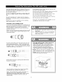
IF YOU SMELL GAS;
1. Shut off gas to the appliance,
2. Extinguish any open flame.
3. Open lid,
4. If odor continues, keep away
from the appliance and immediately
call your gas supplier or your fire
department.
1. Do not store a spare LP cylinder
within 10 feet (3m) of this appliance.
2. Do not store or use gasoline or
other flammable liquids and
vapors within 25 feet (8m) of this
appliance.
3. When cooking with oil or grease, do
not allow the oil or grease to get
hotter than 350°F (177°C),
4. Do not leave oil/grease unattended.
Grill Installation Codes
The installation must conform with local codes
or, in the absence of local codes, with either the
National Fuel Gas Code, ANSI Z223.1/NFPA 54,
or CAN/CGA- B149.1, Natural Gas and Propane
Installation Code.
All electrical accessories (such as a rotisserie or
light) must be electrically grounded in
accordance with local codes, or, in the absence of
local codes, with the National Electrical Code,
ANSI/NFPA 70, or the Canadian Electrical Code,
CSA C22.1. Keep any electrical cords and/or
fuel supply hoses away from all hot surfaces.

Failuretocomplywiththeseinstructionscould
resultinafireorexplosionthatcouldcause
seriousbodilyinjury,deathor property damage.
Spiders and small insects can spin webs and
nest in the grill burner tubes during transit and
warehousing which can lead to a gas flow
obstruction resulting in a fire in and around the
burner tubes. This type of "FLASHBACK FIRE"
can cause serious grill damage and create an
unsafe operating condition for the user.
To reduce the chance of a FLASHBACK FIRE
you must clean the burner tubes as follows
before initial use. Also do this at least once a
month in summer and fall or whenever spiders are
active in your area, and if your grill has not been
used for an extended period of time.
1. Remove the screw from the rear of each burner
using a Phillips head screwdriver.
2.Carefully lift each burner up and away from the
gas valve orifice.
3.Check and clean the burner tubes for insects and
insect nests. A clogged tube can lead to a fire
beneath the grill.
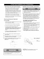
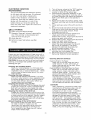
4.Refer to the figure below and perform one of
these 2 cleaning methods:
[] METHOD 1:Use a bottle brush with a flexible
handle and run the brush through the burner
tube and inside the burner several times to
remove any debris.
[] METHOD 2: Use an air hose to force air through
each burner tube. The forced air should pass
debris or obstruction through the burner and
out the ports.
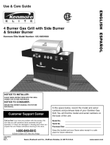
For safe operation ensure the gas valve assembly
orifice is inside the burner tube before using
your grill. See figure. If the orifice is not inside the
burner tube, lighting the burner may cause an
explosion and/or fire resulting in serious bodily
injury and/or property damage.
Gas Valve AssenlNy Orifice 8_Jrne_Tube
Uquid Propane Gas (LPG) grill models must be
used with LP gas and the LP gas regulator
assembly supplied. Natural Gas grill models
must be used with Natural Gas only. Any
attempt to convert the grill from one fuel type
to another is extremely hazardous and will
void the warranty.
Never use your gas grill in a garage, porch,
shed, breezeway or any other enclosed area.
Never obstruct the flow of ventilation air
around your gas grill cabinet.
Never disconnect the gas regulator assembly
or any gas fitting while your grill is lit. A lit grill
can ignite leaking gas and cause a fire or
explosion which could result in property
damage, personal injury or death.
Keep the gas regulator hose or natural gas
hose away from any heated surface and
dripping grease. Avoid unnecessary twisting of
the hose. Visually inspect the hose prior to
each use for cuts, cracks, excessive wear, or
other damage. If the hose appears damaged,
do not use the gas nrill. Call Sears at
1-800-4-MY-HOME® (1-800-469-4663) for a
Kenmore replacement gas hose assembly or
natural gas hose depending on your model.
PRE-ASSEMBLY
Read and perform the following pre-assembly
instructions:
[] Tools Required for Assembly include:
• protective work gloves
• protective eyewear
• Phillips Head Screwdriver (included in
hardware pack in Parts Box)
[] You will need assistance from another person to
handle the grill head and other large, heavy parts.
[] Open lid of shipping carton and remove parts box and
packing materials. Lay a cardboard sheet on floor
and use as a work surface to protect floor and grill
parts from scratches.
[] Slice all four corners with a utility knife to lay open the
carton. This allows you to remove the grill head and
components packed inside.
[] Use the Hardware and Part Diagrams to ensure all
items are included and free of damage.
[] Do not assemble or operate the grill if it appears
damaged. If there are damaged or missing parts
when you unpack the shipping box or you have
questions during the assembly process, call the:
Customer Support Center at 1-800-933-0527
8:30am-S:00pm CST, Monday through Friday.


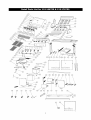
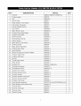
KEY DESCRIPTION PART# QTY
1 Lid Bolt SB0001/SB0002-1/SB0003-1 2
2 Thermometer SE0076 1
3 Lid 06W03-A 1
4 Name Plate ZA0017 1
5 Heat Shield for Lid Handle FE0010 2
6 Lid Handle Connecter ZA0010 2
7 Silicon Stopper for Lid FE0001 2
8 Lid Handle RSA0004 1
9 Back Burner Cover SA0463-1 1
10 Firebox Panel-Rear/Upper SA0412 1
11 Firebox Panel-Rear SA0284 1
12 Warming Rack SA0459-1 1
13 Infrared Back Burner SD0002 1
14 Flame Sensor SC0017 1
15 Back Burner Front Panel SA0028-1 1
16 Cooking Grate SE0004 3
17 Back Burner Electrode SI1350 1
18 Firebox Back Panel SA0455-1 1
19 Heat Diffuser SA0021-1 3
20 Burner Support and Ignition Media SA0460-1 1
21 Firebox Right Panel SA0006-1 1
22 Firebox Left Panel SA0006-1 1
23 Burner SD0001-1 3
24 Lower Heat Shield SA0464-1 1
25 Heat Shield SA0465-1 1
26 Grease Tray SA0461-1/SA0462-1 1
27 Granite Countertop RHA0013 1
28 Countertop Frame 06W03-C-2 1
29 Grease Tray Handle ZA0014 5
30 Smoker Drawer Cover SA0027-1 1
31 Smoker Drawer SA0025-1 1
32 Smoker Drawer Front Panel SA0102-1 1
33 Smoker Drawer Handle SE0025 1
34 Firebox Front Panel SA0454-1 1
35 Gas Manifold Assembly SC0017(LP only)/SC0023(NG only) 1
36 Heat Shield-Control Panel Inner SA0457-3 1
37 Control Panel SA0456-1 1
38 Control Knob Seat ZA0003 5
39 Control Knob ZA0011 5
40 Electric Igniter SE0010 1

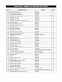
KEY DESCRIPTION PART# QTY
41 Electric Igniter Cap SE0010 1
42 Rotisserie Spit Bracket SA0032-1 1
43 Rotisserie Spit Assembly SE0096 1
44 Rotisserie Spit Left Support SA0033-1 1
45 Side Burner Cover SA0463-1 1
46 Side Burner Frame SA0035-1 1
47 Side Burner Grease Tray Left Support SA0040-1 1
48 Rotisserie Motor SE0091 1
49 Rotisserie Motor Support SA0031-1 1
50 Rotisserie Spit Right Support SA0032-1 1
51 Side Burner Grate CI0001 1
52 Side Burner Electrode SE0052 1
53 Back Burner Fuel Line SH0800 1
54 Side Burner Inner Frame SA0038-1 1
55 Regulator And Hose (LP only) SE0034 1
56 Side Burner Grease Tray SA0041-1/SA0037-1 1
57 Side Burner CI0002 1
58 Side Burner Stem SE0059 1
59 Manual Igniter Stick SE0019 1
60 Ice Chest Back Cover SA0082-1 1
61 Ice Chest Cover Handle SE0013 1
62 Ice Chest Front Cover SA0081-1 1
63 Ice Chest Liner SE0008 1
64 Ice Chest Exterior Handle SE0013 1
65 Ice Chest Exterior SA00481-1 1
66 Ice Chest Drawer SA0291/SA0292/SA0083/SA0084 1
67 Ice Chest Glide Right Support SE0018/SA0087 2
68 Ice Chest Glide Left Support SE0018/SA0088 1
69 Locking Caster SE0023 1
70 Caster SE0021 1
71 Swivel Locking Caster SE0020 1
72 Swivel Caster SE0022 1
73 Cylinder Support Ring (LP only) SE0053 1
74 Cabinet Left Side Panel SA0285 1
75 Cabinet Left-Back Panel SA0288 1
76 Firebox Left Support SA0014 1
77 Firebox Right Support SA0014 1
78 Right-Top Drawer Right Support SA0469/SA0173 1
79 Right-Top Drawer SA0296-1/SA0297-1/SA0298-1/S 1
80 Cabinet Right-Back Panel (LP only) SA0289 1

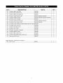
KEY DESCRIPTION PART# QTY
81 Cabinet Back-Top Panel SA0290 1
82 Cabinet Right Side Panel SA0286 1
83 Cabinet Back Panel Bracket SA0072 1
84 Drawer Glide Bracket-Left SA0092/SE0018/SA0287 1
85 Cabinet Middle Drawer SA0294/SA0295/SA0055/SA0056 2
86 Drawer Front Crossbar SA0467 1
87 Drawer Glide Bracket-Right SA0092/SE0018/SA0287 1
88 Cylinder Tray Drawer Door SA0293/SA0291 1
89 Cylinder Tray Glide Mounting Bracket-Left (LP only) SA0089 1
90 Cylinder Tray (LP only) SA0086 1
91 Cabinet Left Side Skirt SA0285 1
92 Cabinet Front Skirt SA0466 1
93 Drawer Connector Crossbar SA0468 1
94 Cabinet Bottom Panel SA0300 1
95 Cabinet Right Side Skirt SA0286 1
96 Cabinet Right-Back Panel (NG only) SA0500 1
97 Gas Hose (NG only) BE0047 1
Detail Part List - Not Show In Diagram
198 IGrill Cover IFO004 I

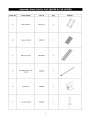
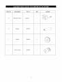
Item No. Description Part # Qty
Heat Diffuser SA0021-1
Cooking Grate
Warming Rack
Rotisserie Spit with
Handle
Meat Fork
Counterweight
SEO004
SA0459-1
SE0096
SE0096
SE0096
Graphic

Item No. Description Part# Qty Graphic
Rotisserie Motor
Battery
Washer
Spit Bushing
SE0091
SEO007
SE0096
SE0096

Please refer to pages 8 and 9 for item graphics.
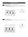
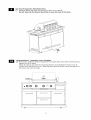
Install Heat Diffusers
[] Install the 3 Heat Diffusers (A) inside the firebox. Ensure the stamped word "Front" on the
Heat Diffusers is placed at the front and their sides fit into the slots on the front and back
of the firebox to secure them in place,
Install Cooking Grates
[] Install the 3 Stainless Steel Cooking Grates (B) into the firebox. The Grates sit on the front
and back lips of the firebox.
10

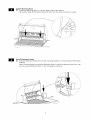
Install Warming Rack
[] Install the Warming Rack (C) into the upper sides of the firebox.
Be sure the sides of the Warming Rack fit down into the slots to secure it in place.
Install Rotisserie Motor
[] Slide the Rotisserie Motor (G) onto the mounting bracket on the right side of the firebox
sidewall
Note: We recommend you store the Rotisserie Motor in one of the drawers when not in use.
Do not use the Rotisserie Motor in rain or expose to moisture.
1!

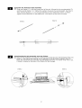
Assemble the Rotisserie Spit Assembly
[] Slide one Washer ( I ) onto the handle end of the spit, followed by the counterweight (F),
and the second Washer ( I ). Tighten the washers to secure the counterweight. See Inset 1.
Then slide the Bushing ( 3 ) on the spit followed by the 2 Meat Forks shown in Inset 2.
Tighten the thumbscrews on the Meat Forks. Use caution as the forks are sharp.
Inset 1 Inset 2
] ,,
Install Rotisserie Spit Assembly onto the firebox
[] Slide the Spit Assembly into place by inserting the pointed end into the Rotisserie Motor (G)
(Inset 1 ) and placing the bushing into its bracket on the left firebox sidewall (Inset 2 ).
Note: We recommend you store the Counterweight and Forks in a drawer when not in use.
A holder is located on the back of the firebox for Spit storage.
Inset 2 Inset i
]3

Install Battery
[] Unscrew the electronic igniter cap. Place the "AA" Battery (H) into the electronic igniter
with the Positive (+) end facing up. Screw the electronic igniter cap back into place on
the electronic igniter.
Battery (Size AA)
Qty: 1
Part # SE0007
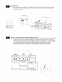
Place LP Cylinder into the Cabinet (LP Hodel Only)
[] Pull the cylinder tray out from the cabinet. Place the LP cylinder down into the tank support
hole. Ensure the valve faces towards the left. Raise the LP cylinder support ring and
unhook as shown asyou push the cylinder tray back into the cabinet. Lock the cylinder
tray in place and lower the LP cylinder support ring over the top of the LP cylinder. Wrap
around the neck of the cylinder and rehook to secure the LP cylinder in place.
Do Not Hook Up the LP Cylinder to the Regulator Assembly at this time.
O
,OO @
13

Gas Hose Preparation (NG Model Only)
[] Feed the Nature Gas Hose out through the back of the cabinet.
Do Not Hook Up the Natural Gas Hose to your Gas Line at this time,
Congratulations - Assembly is now Complete
[] Remove any additional labels and packing from the grill. Be sure to dean all foam packing
material out of all areas.
Please proceed to and read the remaining sections of the Operator's Manual prior to
hooking up or operating your grill. Note that some sections of this manual are specific to
the type of fuel your grill uses.
,QO Q
I I I II
II I I II
II I I II
II I I II
II I I II
II I I II
14

CORRECT LP GAS TANK USE
[] LP gas grill models are designed for use with a
standard 20 lb. (9.1kg) Liquid Propane Gas (LP
G) tank, which is not included with the grill.
Never connect your gas grill to an LP gas tank
that exceeds this capacity. A tank of
approximately 12" (305mm) in diameter by
18-1/2"(472mm) high is the maximum size LP
gas tank to use. You must use an "OPD" gas tank
which offers a listed Overfill Prevention Device.
This safety feature prevents tanks from being
overfilled which can cause malfunction of the LP
gas tank, regulator and grill.
[] The LP gas tank must be constructed and marked
in accordance with the Specifications for LP-Gas
Cylinders of the U.S. Department of
Transportation (D.O.T.) or the National Standard
of Canada, CAN/CSA-B339, Cylinders, Spheres
and Tubes for Transportation of Dangerous
Goods; and Commission, as applicable.
[] The LP gas tank must have a shutoff valve
terminating in a LP gas supply tank valve outlet
that is compatible with a Type 1 tank connection
device. The LP gas tank must also have a safety
relief device that has a direct connection with the
vapor space of the tank.
[] The tank supply system must have a means for
vapor withdrawal.
[] The LP gas tank used must have a collar to
protect the tank valve.
[] Never connect an unregulated LP gas tank to
your gas grill. The gas regulator assembly
supplied with your gas grill is adjusted to have an
outlet pressure of 11"water column (W.C.) for
connection to an LP gas tank. Only use the
regulator and hose assembly supplied with your
gas grill. Replacement regulators and hose
assemblies must be those specified by
Sears. See the Parts List.
[] Have your LP Gas dealer check the release valve
after every filling to ensure it remains free of
defects.
[] Always keep the LP gas tank in an upright
position. Do not subject the LP gas tank to
excessive heat.
[] Never store an LP gas tank indoors. If you store
your gas grill indoors, always disconnect the LPgas
tank first and store it safely outside.
[] LP gas tanks must be stored outdoors in a
well-ventilated area and out of the reach of
children.
[] Disconnected LP gas tanks must not be stored in
a building, garage, or any other enclosed area.
[] The regulator and hose assembly can be seen
after opening the door (if applicable) and must be
inspected before each use of the grill. If there is
excessive abrasion or wear or if the hose is cut, it
must be replaced prior to using the grill.
[] Never light your gas grill with the lid closed or
before checking to ensure the burner tubes are
fully seated over the gas valve orifices.
[] Never allow children to operate your grill. Do not
allow children or pets to play near yourgrill.
[]
[]
[]
[]
[]
[]
[]
[]
[]
Use of alcohol or drugs may impair the ability
to assemble and operate the appliance.
Keep a fire extinguisher readily accessible, tn
the event of an oil or grease fire, do not attempt
to extinguish with water. Use a type B extinguisher
or smother with dirt, sand, or baking soda.
In the event of rain, cover the grill and turn off
the burner and gas supply.
Use your grill on a level, stable surface and ensure
the locking casters are locked before use.
Do not leave the grill unattended when in use.
Do not move the appliance when in use.
Allow the grill to cool before moving or storing.
Do not use your grill as a heater.
This grill is not intended to be installed in or on
recreational vehicles and/or boats.
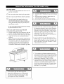
A. Do not store a spare LP gas tank under or
near this appliance.
B. Never fill the tank beyond 80 percent full;
C. If the information in "(A)" and "(B)" is not
followed exactly, a fire causing death or
serious injury may occur.
• Use your grill at least 2 feet away from
any wall or surface. Use your grill at
least 2 feet away from combustible objects
that can melt or catch fire (such as vinyl or
wood siding, fences and overhangs) or
sources of ignition including pilot lights on
water heaters and live electrical appliances.
• Never use your gas grill in a garage, porch,
shed, breezeway, or any other enclosed area.
• Never obstruct the flow of ventilation air
around your gas grill housing.
]5

Notes about LP Gas Tank Exchange Programs
• Many retailers that sell grills offer you the option of
replacing your empty LP gas tank through an
exchange service. Use only those reputable
exchange companies that inspect, precision fill, test
and certify their tanks. Exchange your tank only for
an OPD safety feature equipped tank as described
in the LP gas tank section of this manual.
• Always keep new and exchanged LP gas tanks in an
upright position during use, transit or storage.
• Leak test new and exchanged LP gas tanks BEFORE
connecting one to your grill.
How to Leak Test your LP Gas Tank
For your safety:
• All leak tests must be repeated each time your LP gas
tank is exchanged or refilled.
Do not smoke when checking for gas leaks.
• Do not use an open flame to check for gas leaks.
Your grill must be leak tested outdoors in a
well-ventilated area, away from ignition sources such
as gas fired or electrical appliances. During the leak
test, keep your grill away from open flames or
sparks.
• Do not use household cleaning agents as damage to
gas assembly components can occur.
Regulator and LP Cylinder Connections
The gas pressure regulator provided with this
outdoor cooking appliance must be used. This
regulator is set for an outlet pressure of 11
inches water column.
Your regulator is equipped with a Q.C.C. Type 1
quick connect system. It will not allow gas to flow
until a positive seal has been made. It has a
thermal element that will shut off the gas flow if
the temperature reaches 240 degrees F (115
degrees C). It also has a flow-limiting device that
will restrict the flow of gas to 10 cubic feet per
hour (0.28 cubic meters per hour).
TO CONNECT THE CYLINDER TO THE
REGULATOR AND HOSE
1. Be sure the LP cylinder is "OFF" by turning the
hand wheel clockwise until it stops.
2. Place the cylinder into the base cabinet shelf of
the grill with the valve facing outward and
secure with the cylinder support ring.
3. Be sure all burner controls are turned to the
"OFF" position.
4. Remove the safety cap from the cylinder valve.
5. Center the nipple of the regulator into the
cylinder valve.
6. Turn the black nut clockwise until it stops.
Hand Tighten Only, Do Not Use A Wrench.
[]
[]
[]
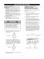
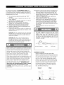
Use a clean paintbrush and a 50/50 mild soap and
water solution.
Brush soapy solution onto the LPgas tank in the areas
indicated by the arrows. See diagram.
Ifgrowing bubbles appear do not use or move the LP
Gas tank. Call an LP gas supplier or your fire
department.
Type I c_nection per
If growing bubbles appear do not use or move
the LP Gas tank. Contact an LP gas Supplier or
your fire department!
CAUTION: When the appliance is not in use
the gas must be turned off at the tank.
]6

Flow Limiting Valves on LP Gas Tanks
Your LP gas tank is equipped with a flow limiting
valve that wilt restrict the flow of gas due to a
sudden change in pressure. This can often
activate without your knowledge. You will notice
among olher things that your grtl does not get as
hot as it should, witl take longer to heat up or
you may not be able to light all burners. If you
notice any of the above, then you should reset
the valve and clear' your gas _ine
?b do this
;_ Ensure the LP gas tank valve is OFR
2 Disconnect the regulator from the LP gas
tank,
3. Open aH burnercontrot knobs including the
side burner to Hi/Light at the same time.
4_ Close all burner control knobs to OFR
5. Let the LP gas tank stand for at _east _0
minutes,
6_ Reconnect the regulator assemUy to the LP
gas Lank
7. Slowly, meaning about 1/4 turn at a Lime,
bJm on the LP gas valve.
8. Follow the burner lighting procedures to
light the burner farthest away from the gas
source
9. ]he flow limiting valve should now be reset
This flow limiting Valve is triggered by sudden
changes in pressure This can be caused by a leak,
faulb/connection of the regulator to t_e LP gas
tank, turning on the LP gas tank valve too quickly,
or turning the burners off by turning the LP gas
tank valve off before turning the burner control
knobs to offl Note: aJways turn off your burners
using the burner contro! knobs first before turning
the LP gas tank valve off.
Transportation and Storage
l, "Place a dust cap on the cylindel vave outlet
whenever the cylinder is not in use. Only
install the type of dust cap on the cylinder
valve outiet that is provided wth the
cylinder of propane valve. Other types of
caps or plugs may result in leakage.
2. Always transport your cylinder in an upright
position,
3, Do not smoke whe_ transporting your
Check aH connections for LP Gas _eaks
D Never test for leaks with a fiame_ Prior to
first use, at the beginning of each season
or every time your LP Gas tank is changed
you must check for gas teaks. Follow
these three steps:
Hakea soap solut on by mixingo e part
liquid detergent and one part water
D
D
[urn the burner contro_ knobs to tse OFF
position Then turn the gas ON at the source.
Appty the soap sotution to aH gas :onnections
indicated by the arrows. See diag am. _f
bubbles appear in the soap solution the
connections are not properly sealed Check
each fitting and tighten or repair as
necessary
Gas Va/ae Manifold
Assembly
L_
J
Hose
ill you have a gas leak that cannot be repaired
by tightening turn off the gas at the
source, disconnect fuel line from yot. r grill
and ca_l 1-800_4_Myo.HOHE@ or yo/.. °
gas supplier for repar ass stance.
Disconnecting A Liquid Propa_e Gas (LPG}
Tank From Your Grill
_} Hake sure the burner valves and .P gas
tank valve are of£ (Turn clockwise
[Z Detach the hose and regulator ass(; mMy
from the LP gas taJ'_k valve by turr ng the
quick coupling nut counterc ockwise

YournewgasgrilloperatesonNaturalGas.It is
colorlessandodorlessinitsnaturalform.Theform
ofnaturalgasthatisdeliveredtoyourhomeis
almostpuremethane.
Yourgrillisdesignedtooperateonnaturalgasonly.
Donot,forsafetyreasons,useanyothertypeof
fuel.
Yourgrilloperatesat7"watercolumnpressure.
Contactyourlocalgasutilityforthegaspressurein
yourarea.
Contactyourlocalmunicipalityforanybuilding
coderequirementsinyourarea.
NATURAL GAS CONNECTION
A shut-off valve should already be installed at the
gas source outside of the house or where the pipe
exits the ground. If not, then one must be
installed before installing the quick-disconnect
hose for your grill.
Attach the quick-disconnect socket to the shut-off
valve. Use pipe dope or pipe thread tape on the
male pipe thread.
In the event of rain, cover the grill and turn off
the burner and gas supply.
Use your grill on a level, stable surface and ensure
the locking casters are locked before use.
Do not leave the grill unattended when in use.
Do not move the appliance when in use.
Allow the grill to cool before moving or storing.
Do not use your grill as a heater.
This grill is not intended to be installed in or on
recreational vehicles and/or boats.
A. Do not store a gas tank under or near this
appliance.
B. If the information in "(a)" is not followed
exactly, a fire causing death or serious
injury may occur.
Push the male fitting from the gas hose into the
quick-disconnect socket. Push in the plug until
the sleeve from the socket snaps forward locking
the plug in place. This will activate the flow of gas
if the shut-off valve is turned on.
Disconnect the plug by pushing the sleeve back
towards the socket.
Use of alcohol or drugs may impair the ability
to assemble and operate the appliance.
Keep a fire extinguisher readily accessible. In
the event of an oil or grease fire, do not
attempt to extinguish with water. Use a type B
extinguisher or smother with dirt, sand, or
baking soda.
• Use your grill at least 2 feet away from
any wall or surface. Use your grill at
least 2 feet away from combustible objects
that can melt or catch fire (such as vinyl or
wood siding, fences and overhangs) or
sources of ignition including pilot lights on
water heaters and live electrical appliances.
• Never use your gas grill in a garage, porch,
shed, breezeway, or any other enclosed area.
• Never obstruct the flow of ventilation air
around your gas grill housing.
J
2_
]8

For your safety;
[] A leak test must be repeated each time your NG
gas line is connected
[] Do not smoke when checking for gas leaks.
[] Do not use an open flame to check for gas leaks.
[]
Your grill must be leak tested outdoors in a
well-ventilated area, away from any ignition
source such as gas fired or electrical appliances.
During the leak test, keep your grill away from
open flames or sparks.
Do not use household cleaning agents as damage
to gas components can occur.
How to do Leak Test on your NG Grill
1. Ensure all burners are "Off"
2. Ensure the gas hose is connected to the gas
source, and the shutoff valve is turned on.
3. Nix up a solution of 50% dish soap and 50%
water. Do not use any household cleaner
solution.
4. Spray or brush on the solution covering the
following area: gas hose connections to the
shut-off valve, gas hose, and the gas hose
connection to the gas manifold assembly.
Growing bubbles on any of the parts and
connections listed above indicate a gas leak
1. DO NOT USE THE GRILL if you cannot stop a
leak.
2. Do not use any match or open flame, or
smoke, during leak testing•
3. Do not light a burner during leak testing.
1. Before each use, check the natural gas hose
for excessive abrasion, wear or cuts. Replace a
gas hose showing those signs with the hose
specified in the parts list before using the grill.
Inspect the hose by opening the cabinet door
underneath the right main burner and
following the gas hose up to its connection to
the gas manifold assembly•
2. Always perform the Leak Test listed above
before using your grill for the first time, if the
natural gas connection has been changed, any
gas components have been changed, or after
a long period of non-use.
1. This outdoor cooking gas appliance and its
individual shutoff valve must be disconnected
from the gas supply piping system during any
pressure testing of that system at test
pressures in excess of 0.Spsi (3.SkPa).
2. This outdoor cooking gas appliance must be
isolated from the gas supply piping system by
closing its individual manual shutoff valve
during any pressure testing of the gas supply
piping system at test pressures equal to or
less than 1/2 psi (3.SkPa).
If you have a gas leak that cannot be
repaired by tightening, turn off the gas at
the source, disconnect fuel line from your
grill and call 1-800-4-MY-HOlE® or your
gas supplier for repair assistance.
]9

lain Burner Instructions
Lighting The Main Burners With Push And
Turn Ignition
1. Before each use, check all hoses for cracks,
nicks, cuts, or abrasions. If a hose is
damaged in any way, do not use your grill
before replacing the hose with an authorized
part from the Parts List. Also make sure all
gas supply connections are securely
tightened.
2. Familiarize yourself with the Safety and Use
and Care instructions in this manual. Do not
smoke while lighting the grill or checking gas
supply connections.
3. Be sure the LP gas tank has gas.
4. Open the grill lid.
5. Check that the end of each burner tube is
properly located over each valve orifice.
Failure to replace a faulty hose, secure gas
supply connections, or to open the lid
before proceeding to the Lighting
Procedures could result in a fire or
explosion that could cause serious bodily
injury, death, or property damage.
6,
Set Control Knobs to OFF and open the LP
gas tank valve SLOWLY or turn on the
natural gas.
i
OFF
HI/LIGHT
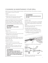
7,
LOW
Push in the burner control knob of the
burner you wish to light and turn left to
"HI/LIGHT". You will hear a click as a spark is
sent to the burner. If the burner does not
light, then turn back to "OFF, and repeat
this procedure. Continue this process until
the burner lights.
i
OFF
HI/LIGHT
LOW
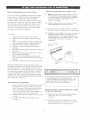
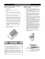
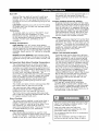
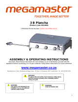
Side Burner and Back Burner
Lighting Instructions
Lighting The Side Burner Or Back
Burner With Electronic Ignition
Follow steps 1 through 5 of the Grill Lighting
Instructions.
1. Open side burner or grill lid.
2. Set control knobs to OFF and open the LP
gas tank valve SLOWLY or turn on the
natural gas.
3. Push and turn the side or back burner
control knob to "HI/LIGHT".
4.
Immediately press the electric igniter
button for 3-5 seconds to light the burner.
You should hear a clicking sound which
shows the electronic ignition is working.
Ifthe burner does not light within 5
seconds, turn the burner control knob to
"Off". Wait 5 minutes for the gas to
clear, and repeat the above procedure.
6,
For the back burner, continue to push and
hold the burner control knob in for 5 to 7
seconds after the burner lights until the
flame sensor begins operating. Letting up
on the burner control knob before a high
enough temperature has been reached
may cause the flame sensor to shut off
fuel to the back burner.
Back burner
Side burner Smoker drawer
Electronic ignition Main burners
8. When lit, turn the burner control knob to its
desired heat setting.
2O
Page is loading ...
Page is loading ...
Page is loading ...
Page is loading ...
Page is loading ...
Page is loading ...
Page is loading ...
Page is loading ...
Page is loading ...
-
 1
1
-
 2
2
-
 3
3
-
 4
4
-
 5
5
-
 6
6
-
 7
7
-
 8
8
-
 9
9
-
 10
10
-
 11
11
-
 12
12
-
 13
13
-
 14
14
-
 15
15
-
 16
16
-
 17
17
-
 18
18
-
 19
19
-
 20
20
-
 21
21
-
 22
22
-
 23
23
-
 24
24
-
 25
25
-
 26
26
-
 27
27
-
 28
28
-
 29
29


Kenmore 119.166750 Owner's manual
- Category
- Barbecues & grills
- Type
- Owner's manual
- This manual is also suitable for
Ask a question and I''ll find the answer in the document
Finding information in a document is now easier with AI
Related papers
-
Centro Barbecue Stainless 4000B Safe use User guide
-
Kenmore 41523666310 Owner's manual
-
Charbroil 415.16645900 Owner's manual
-
-
Charbroil 415.16661 Owner's manual
-
Char-Broil 41516106210 Owner's manual
-
-
 Kenmore Elite 14630212510 Owner's manual
-
-
 Kenmore Elite 810-9445-0 Owner's manual


Other documents
-
Member's Mark BQ05046-6N-A Owner's manual
-
-
-
-
Dyna-Glo DGF571CRP-D Operating instructions
-
-
 Megamaster 820-0055 Owner's manual
-
 Elevate Grill ELVGRL-B User manual
-
River of Goods 14006 Operating instructions
-
Members Mark BQ05046-6 Owner's manual

