
ADDENDUM
Residential Split Systems
These instructions are intended primarily to assist qualified individuals experienced in the proper
installation of this appliance. Some local codes require licensed installation/service personnel
for this type of equipment. Read all instructions carefully before starting the installation.
Installation, service, and repair of air conditioning units must be performed by trained service
technicians only. Death, personal injury, or property damage may occur due to improper
installation, system alteration, or system maintenance. It is important that qualified installers
use factory approved accessories and kits when modifying any systems.
DO NOT DESTROY. PLEASE READ CAREFULLY AND KEEP IN A SAFE PLACE FOR FUTURE REFERENCE.
WARNING:
Application Guidelines for Refrigerant Lines
SAFETY INFORMATION
Please read all instructions before servicing this
equipment. Pay attention to all safety warnings and any
other special notes highlighted in the manual. Safety
markings are used frequently throughout this manual to
designate a degree or level of seriousness and should
not be ignored.
WARNING indicates a potentially hazardous situation
that if not avoided, could result in personal injury or death.
CAUTION indicates a potentially hazardous situation that
if not avoided, may result in minor or moderate injury or
property damage.
WARNING:
To avoid the risk of electrical shock, personal
injury, or death, disconnect all electrical power
to the unit before performing any maintenance
or service and follow all warning labels. The unit
may have more than one electrical power supply.
• It is the responsibility of the installer to ensure that the
installation is made in accordance with all applicable
local and national codes.
• Be sure to read this document thoroughly and
understand all procedures before attempting installation
or modification of the system. Wear safety glasses,
protective clothing, and work gloves. Have a fire
extinguisher handy during installation and use a
quenching cloth for brazing operations.
• Installed equipment must be in compliance with all
national and local codes. Disconnect power to the unit
before any electric service is attempted and follow all
warning labels on the unit.
GENERAL INFORMATION
These guidelines apply to all NORDYNE residential R410-A
split system air conditioners and heat pumps with nominal
capacities under 65,000 Btu. The installation instructions
provided with the equipment specify a maximum equivalent
line length of 75 feet. This guideline covers applications
with equivalent line lengths up to 175 feet.
Thermal expansion valves may be used in air conditioner
and heat pump systems. When properly installed, the TXV
will adjust the refrigerant flow by monitoring the superheat
of the system.
• Ifpreciseformingofrefrigerantlinesisrequired,acopper
tubing bender is recommended. Avoid sharp bends and
contact of the refrigerant lines with metal surfaces.
• Refrigerant lines should be wrapped with pressure
sensitive neoprene or other suitable material where
they pass against sharply edged sheet metal.
• Itisgoodpracticetoaddadropofrefrigerantoilonall
threaded connections.
REFRIGERANT LINE CONSIDERATIONS
WARNING:
Refrigeration equipment contains liquid and
gaseous refrigerant under high pressure.
Installation or servicing should only be
performed by trained personnel thoroughly
familiar with this type of equipment.
• Alwaysusesafeandenvironmentallysoundmethodsfor
refrigerant handling. When repairing system leakages,
always utilize a nitrogen (inert) gas to protect the
refrigerant system and pressure check the repair before
re-charging.

2
• Alwaysreplacethelter-dryerswhenperformingany
repair to the refrigeration system with one capable of
acid removal. After completing the repairs, evacuate the
system to 350-500 microns and weigh in the refrigerant
to the amount specified in the Quick Reference Data
sheet or the unit’s rating plate.
CAUTION:
To prevent damage to the unit or internal
components, it is recommended that two
wrenches be used when loosening or removing
lines. Do not over tighten!
• Propersizingoftherefrigerantlinesiscriticaltomaintain
satisfactory performance and reliability. Many factors
are involved in determining refrigerant line size include:
length of horizontal run, length of vertical risers, number
and placement of fittings, placement of the condensing
unit to the evaporator, and total equivalent line length.
CAUTION:
To prevent damage to the TXV, brazing should
be done prior to the attachment of the liquid
line to the fitting assembly.
CAUTION:
It is recommended that a wet rag be wrapped
around the suction line in front of the close
off plate before applying heat. Failure to keep
components cool during brazing may result
in structural damage, premature equipment
failure, or possible personal injury.
• Itisrecommendedthatallsystemsinstalledinlong-line
applications use only 3/8” liquid lines. Use of larger liquid
lines will significantly increase the system charge and
could lead to liquid refrigerant related failures of the
compressor. Static head and friction losses in liquid
lines must be minimized to avoid refrigerant flashing.
• Thevaporlinemustbesizedsothatrefrigerantvelocities
are high enough to return oil to the compressor. Low
refrigerant velocities can result in loss of lubrication
failures of the compressor.
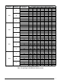
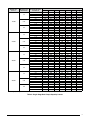
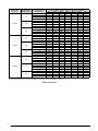
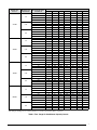
NOTE: The ASHRAE Fundamentals recommend a
refrigerant velocity under low load conditions of 500 feet
per minute in horizontal runs and 1000 feet per minute
in vertical risers. The approximate cooling capacity loss
for various vapor line sizes and equivalent lengths are
shown in Tables 1 - 4 (pages 3 - 8). Equivalent length
is the total linear length of vapor line plus additional
equivalent lengths for all fittings and elbows. See Table
7 (page 9) for fitting lengths.
• Usespecialcaretoisolatetherefrigerantlinesfromthe
structure to prevent vibration and/or noise from being
transmitted to the structure.
RESTRICTOR SIZING
Long refrigerant line runs result in increased frictional
owlosses.Inordertocompensatefortheselosses,the
restrictor(s)mustbere-sizedperthefollowingtables.Ifthe
total equivalent horizontal length is greater than 100 feet,
the restrictor(s) bore must be increased by .001 inches
over the value shown in Table 6 (page 9).
IftherequiredrestrictorsizedeterminedfromTable6is
a non-standard size, round up to the nearest standard
restrictor size.
CHARGING
All split systems are factory shipped with the refrigerant
charge noted on the unit nameplate. This charge is for a
typical application of 15 feet of actual line length. Systems
installed with more than 25 feet of refrigerant line should
be charged following the charging method described in
the installation instructions. No additional oil charge is
required for these applications.
ADDITIONAL COMPONENTS
• Forequivalentlinelengthsabove100feet,acompressor
crankcase heater is required.
• Forapplicationswheretheoutdoorunitismorethan50
feet above the indoor unit, an oil trap must be installed
in the vapor line at the 50 foot elevation and every 40
feet above 50 feet.
• For applications with a vertical separation of more
than 75 feet between the indoor and outdoor units, a
liquid line solenoid kit must be installed within 10 feet
of the outdoor unit. An anti-short cycle timer (ASCT) is
recommended for all applications with vertical separation
above 75 feet. Note that ASCT is standard on all heat
pumps and many electronic thermostats. See Table 5
(page 9).

3
Table 1. Single Stage Air Conditioners Capacity Losses
NomiNal UNit
CapaCity
maximUm liqUid
liNe diameters
exteNded rUN Vapor
liNe diameter
perCeNt NomiNal CooliNg CapaCity Vs. eqUiValeNt liNe leNgth
25 ft. 50 ft. 75 ft. 100 ft. 125 ft. 150 ft. 175 ft.
18,000
1/4
5/8 100 100 100 100 99 99 99
3/4 100 100 100 100 100 100 100
7/8 100 100 100 100 100 100 100
1 1/8 100 100 100 100 100 100 100
5/16
5/8 100 100 99 99 99 98 98
3/4 100 100 100 100 100 100 100
7/8 100 100 100 100 100 100 100
1 1/8 100 100 100 100 100 100 100
3/8
5/8 100 99 99 99 99 98 98
3/4 100 100 100 100 99 99 99
7/8 100 100 100 100 100 100 100
1 1/8 100 100 100 100 100 100 100
24,000
1/4
5/8 100 99 99 98 98 97 96
3/4 100 100 100 100 99 99 99
7/8 100 100 100 100 100 100 99
1 1/8 100 100 100 100 100 100 100
5/16
5/8 100 99 99 98 98 97 97
3/4 100 100 100 100 100 99 99
7/8 100 100 100 100 100 100 100
1 1/8 100 100 100 100 100 100 100
3/8
5/8 100 100 99 98 97 97 96
3/4 100 100 100 100 99 99 99
7/8 100 100 100 100 100 100 100
1 1/8 100 100 100 100 100 100 100
30,000
1/4
5/8 100 99 98 98 97 96 95
3/4 100 100 100 99 99 99 99
7/8 100 100 100 100 100 100 100
1 1/8 100 100 100 100 100 100 100
5/16
5/8 100 99 98 97 96 96 95
3/4 100 100 99 99 99 99 98
7/8 100 100 100 100 100 99 99
1 1/8 100 100 100 100 100 100 100
3/8
5/8 100 99 98 97 96 96 95
3/4 100 100 99 99 99 98 98
7/8 100 100 100 100 100 99 99
1 1/8 100 100 100 100 100 100 100
36,000
1/4
5/8 100 98 97 95 93 92 90
3/4 100 99 99 98 97 96 95
7/8 100 100 99 99 98 97 97
1 1/8 100 100 100 99 99 98 98
5/16
5/8 99 98 97 96 95 93 92
3/4 100 100 99 99 98 98 97
7/8 100 100 100 100 99 99 99
1 1/8 100 100 100 100 100 100 100
3/8
5/8 99 98 97 96 94 93 92
3/4 100 100 99 99 98 98 97
7/8 100 100 100 100 99 99 99
1 1/8 100 100 100 100 100 100 100
Cells shaded in gray are not recommended due to low vapor velocities through the compressor.

4
NomiNal UNit
CapaCity
maximUm liqUid
liNe diameters
exteNded rUN Vapor
liNe diameter
perCeNt NomiNal CooliNg CapaCity Vs. eqUiValeNt liNe leNgth
25 ft. 50 ft. 75 ft. 100 ft. 125 ft. 150 ft. 175 ft.
42,000
1/4
5/8 100 98 96 95 93 91 90
3/4 100 100 99 98 97 97 96
7/8 100 100 100 100 99 99 99
1 1/8 100 100 100 100 100 100 100
5/16
5/8 99 98 96 95 93 92 90
3/4 100 99 99 98 98 97 97
7/8 100 100 100 100 99 99 99
1 1/8 100 100 100 100 100 100 100
3/8
5/8 99 98 96 95 93 92 90
3/4 100 99 99 98 98 97 97
7/8 100 100 100 99 99 99 99
1 1/8 100 100 100 100 100 100 100
48,000
1/4
5/8 100 98 95 93 91 88 86
3/4 100 100 99 98 96 95 94
7/8 100 100 100 99 98 97 96
1 1/8 100 100 100 100 99 99 98
5/16
5/8 99 97 95 94 92 90 88
3/4 100 99 99 98 97 97 96
7/8 100 100 100 100 99 99 99
1 1/8 100 100 100 100 100 100 100
3/8
5/8 99 97 95 94 92 90 88
3/4 100 100 99 98 97 97 96
7/8 100 100 100 100 99 99 99
1 1/8 100 100 100 100 100 100 100
60,000
1/4
5/8 98 95 92 N/A N/A N/A N/A
3/4 99 98 97 N/A N/A N/A N/A
7/8 100 100 99 N/A N/A N/A N/A
1 1/8 100 100 100 N/A N/A N/A N/A
5/16
5/8 98 95 93 90 87 85 82
3/4 99 98 97 96 95 94 93
7/8 100 100 99 98 98 97 97
1 1/8 100 100 100 100 100 100 100
3/8
5/8 98 95 93 90 87 85 82
3/4 99 98 97 96 95 94 93
7/8 100 99 99 98 98 97 97
1 1/8 100 100 100 100 100 100 99
Cells shaded in gray are not recommended due to low vapor velocities through the compressor.
Table 1. Continued

5
Table 2. Single Stage Heat Pumps Capacity Losses
NomiNal UNit
CapaCity
maximUm liqUid
liNe diameters
exteNded rUN Vapor
liNe diameter
perCeNt NomiNal CooliNg CapaCity Vs. eqUiValeNt liNe leNgth
25 ft. 50 ft. 75 ft. 100 ft. 125 ft. 150 ft. 175 ft.
18,000
1/4
5/8 100 100 99 99 99 98 98
3/4 100 100 100 100 100 100 100
7/8 100 100 100 100 100 100 100
1 1/8 100 100 100 100 100 100 100
5/16
5/8 100 99 99 99 99 98 98
3/4 100 100 100 100 100 100 100
7/8 100 100 100 100 100 100 100
1 1/8 100 100 100 100 100 100 100
3/8
5/8 100 99 99 98 98 98 97
3/4 100 100 100 100 100 100 100
7/8 100 100 100 100 100 100 100
1 1/8 100 100 100 100 100 100 100
24,000
1/4
5/8 100 99 98 97 96 95 94
3/4 100 100 99 99 98 98 97
7/8 100 100 100 100 100 99 99
1 1/8 100 100 100 100 100 100 100
5/16
5/8 100 99 98 97 96 95 95
3/4 100 100 100 100 100 99 99
7/8 100 100 100 100 100 100 100
1 1/8 100 100 100 100 100 100 100
3/8
5/8 100 99 99 98 98 97 97
3/4 100 100 100 100 99 99 99
7/8 100 100 100 100 100 100 100
1 1/8 100 100 100 100 100 100 100
30,000
1/4
5/8 100 99 98 97 96 95 94
3/4 100 100 99 99 98 98 97
7/8 100 100 100 99 99 99 98
1 1/8 100 100 100 100 100 100 100
5/16
5/8 99 99 98 97 96 95 95
3/4 100 100 99 99 99 99 98
7/8 100 100 100 100 100 99 99
1 1/8 100 100 100 100 100 100 100
3/8
5/8 99 98 98 97 96 95 94
3/4 100 100 99 99 99 98 98
7/8 100 100 100 100 100 99 99
1 1/8 100 100 100 100 100 100 100
36,000
1/4
5/8 100 98 97 95 94 92 91
3/4 100 100 99 98 98 97 96
7/8 100 100 100 99 99 98 98
1 1/8 100 100 100 100 100 99 99
5/16
5/8 99 98 97 95 94 93 92
3/4 100 100 99 99 98 98 98
7/8 100 100 100 100 100 99 99
1 1/8 100 100 100 100 100 100 100
3/8
5/8 99 97 96 95 93 92 91
3/4 100 99 99 98 98 97 97
7/8 100 100 100 99 99 99 99
1 1/8 100 100 100 100 100 100 100
Cells with gray shading are not recommended due to low vapor velocities through the compressor.

6
NomiNal UNit
CapaCity
maximUm liqUid
liNe diameters
exteNded rUN Vapor
liNe diameter
perCeNt NomiNal CooliNg CapaCity Vs. eqUiValeNt liNe leNgth
25 ft. 50 ft. 75 ft. 100 ft. 125 ft. 150 ft. 175 ft.
42,000
1/4
5/8 99 97 95 94 92 90 88
3/4 100 99 98 97 97 96 95
7/8 100 100 99 99 98 98 97
1 1/8 100 100 100 99 99 99 98
5/16
5/8 99 97 96 94 93 91 89
3/4 100 100 99 98 98 97 96
7/8 100 100 100 99 99 99 99
1 1/8 100 100 100 100 100 100 100
3/8
5/8 99 97 95 94 92 90 89
3/4 100 99 99 98 98 97 97
7/8 100 100 100 99 99 99 99
1 1/8 100 100 100 100 100 100 100
48,000
1/4
5/8 100 98 96 94 92 90 87
3/4 100 100 100 98 97 96 95
7/8 100 100 100 99 99 98 97
1 1/8 100 100 100 100 100 100 99
5/16
5/8 98 97 95 93 92 90 N/A
3/4 100 100 99 99 98 98 98
7/8 100 100 100 100 100 100 100
1 1/8 100 100 100 100 100 100 100
3/8
5/8 98 96 94 92 90 88 86
3/4 100 99 98 98 97 96 96
7/8 100 100 100 99 99 99 99
1 1/8 100 100 100 100 100 100 100
60,000
1/4
5/8 N/A 100 96 93 90 N/A N/A
3/4 N/A 100 100 100 99 N/A N/A
7/8 N/A N/A N/A 100 100 N/A N/A
1 1/8 100 100 100 100 100 N/A N/A
5/16
5/8 98 96 93 91 89 86 84
3/4 100 100 100 99 99 98 98
7/8 100 100 N/A N/A N/A N/A N/A
1 1/8 100 100 100 100 100 100 100
3/8
5/8 97 94 91 88 85 83 80
3/4 99 99 98 97 96 95 94
7/8 100 100 100 99 99 99 99
1 1/8 100 100 100 100 100 100 100
Cells with gray shading are not recommended due to low vapor velocities through the compressor.
Table 2. Continued

7
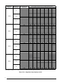
Table 3. Two - Stage Air Conditioner Capacity Losses
NomiNal UNit
CapaCity
maximUm liqUid
liNe diameters
exteNded rUN Vapor
liNe diameter
perCeNt NomiNal CooliNg CapaCity Vs. eqUiValeNt liNe leNgth
25 ft. 50 ft. 75 ft. 100 ft. 125 ft. 150 ft. 175 ft.
24,000
1/4
5/8 100 99 99 98 98 97 96
3/4 100 100 100 100 99 99 99
7/8 100 100 100 100 100 100 99
1 1/8 100 100 100 100 100 100 100
5/16
5/8 100 99 99 98 98 97 97
3/4 100 100 100 100 100 99 99
7/8 100 100 100 100 100 100 100
1 1/8 100 100 100 100 100 100 100
3/8
5/8 100 100 99 98 97 97 96
3/4 100 100 100 100 99 99 99
7/8 100 100 100 100 100 100 100
1 1/8 100 100 100 100 100 100 100
36,000
1/4
5/8 100 98 97 95 93 92 90
3/4 100 99 99 98 97 96 95
7/8 100 100 99 99 98 97 97
1 1/8 100 100 100 99 99 98 98
5/16
5/8 99 98 97 96 95 93 92
3/4 100 100 99 99 98 98 97
7/8 100 100 100 100 99 99 99
1 1/8 100 100 100 100 100 100 100
3/8
5/8 99 98 97 96 94 93 92
3/4 100 100 99 99 98 98 97
7/8 100 100 100 100 99 99 99
1 1/8 100 100 100 100 100 100 100
48,000
1/4
5/8 100 98 95 93 91 88 86
3/4 100 100 99 98 96 95 94
7/8 100 100 100 99 98 97 96
1 1/8 100 100 100 100 99 99 98
5/16
5/8 99 97 95 94 92 90 88
3/4 100 99 99 98 97 97 96
7/8 100 100 100 100 99 99 99
1 1/8 100 100 100 100 100 100 100
3/8
5/8 99 97 95 94 92 90 88
3/4 100 100 99 98 97 97 96
7/8 100 100 100 100 99 99 99
1 1/8 100 100 100 100 100 100 100
60,000
1/4
5/8 98 95 92 N/A N/A N/A N/A
3/4 99 98 97 N/A N/A N/A N/A
7/8 100 100 99 N/A N/A N/A N/A
1 1/8 100 100 100 N/A N/A N/A N/A
5/16
5/8 98 95 93 90 87 85 82
3/4 99 98 97 96 95 94 93
7/8 100 100 99 98 98 97 97
1 1/8 100 100 100 100 100 100 100
3/8
5/8 98 95 93 90 87 85 82
3/4 99 98 97 96 95 94 93
7/8 100 99 99 98 98 97 97
1 1/8 100 100 100 100 100 100 99
Cells with gray shading are not recommended due to low vapor velocities through the compressor.

8
Table 4. Two - Stage Heat Pump Capacity Losses
NomiNal UNit
CapaCity
maximUm liqUid
liNe diameters
exteNded rUN Vapor
liNe diameter
perCeNt NomiNal CooliNg CapaCity Vs. eqUiValeNt liNe leNgth
25 ft. 50 ft. 75 ft. 100 ft. 125 ft. 150 ft. 175 ft.
24,000
1/4
5/8 100 99 98 97 96 95 94
3/4 100 100 99 99 98 98 97
7/8 100 100 100 100 100 99 99
1 1/8 100 100 100 100 100 100 100
5/16
5/8 100 99 98 97 96 95 95
3/4 100 100 100 100 100 99 99
7/8 100 100 100 100 100 100 100
1 1/8 100 100 100 100 100 100 100
3/8
5/8 100 99 99 98 98 97 97
3/4 100 100 100 100 99 99 99
7/8 100 100 100 100 100 100 100
1 1/8 100 100 100 100 100 100 100
36,000
1/4
5/8 100 98 97 95 94 92 91
3/4 100 100 99 98 98 97 96
7/8 100 100 100 99 99 98 98
1 1/8 100 100 100 100 100 99 99
5/16
5/8 99 98 97 95 94 93 92
3/4 100 100 99 99 98 98 98
7/8 100 100 100 100 100 99 99
1 1/8 100 100 100 100 100 100 100
3/8
5/8 99 97 96 95 93 92 91
3/4 100 99 99 98 98 97 97
7/8 100 100 100 99 99 99 99
1 1/8 100 100 100 100 100 100 100
48,000
1/4
5/8 100 98 96 94 92 90 87
3/4 100 100 100 98 97 96 95
7/8 100 100 100 99 99 98 97
1 1/8 100 100 100 100 100 100 99
5/16
5/8 98 97 95 93 92 90 N/A
3/4 100 100 99 99 98 98 98
7/8 100 100 100 100 100 100 100
1 1/8 100 100 100 100 100 100 100
3/8
5/8 98 96 94 92 90 88 86
3/4 100 99 98 98 97 96 96
7/8 100 100 100 99 99 99 99
1 1/8 100 100 100 100 100 100 100
60,000
1/4
5/8 N/A 100 96 93 90 N/A N/A
3/4 N/A 100 100 100 99 N/A N/A
7/8 N/A N/A N/A 100 100 N/A N/A
1 1/8 100 100 100 100 100 N/A N/A
5/16
5/8 98 96 93 91 89 86 84
3/4 100 100 100 99 99 98 98
7/8 100 100 N/A N/A N/A N/A N/A
1 1/8 100 100 100 100 100 100 100
3/8
5/8 97 94 91 88 85 83 80
3/4 99 99 98 97 96 95 94
7/8 100 100 100 99 99 99 99
1 1/8 100 100 100 100 100 100 100
Cells with gray shading are not recommended due to low vapor velocities through the compressor.

9
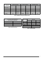
Indoor Restrictor Bore Size Reduction
(Air Conditioner and Heat pump)
Vertical Separation (Feet) Restrictor Size Change
75 - 100 -0.007
101 - 125 -0.009
126 - 150 -0.01
151 - 175 -0.011
NOTE:IfunitisequippedwithaTXV,nochangeisrequired
Table 6. Restrictor Sizing
Tube O.D. (in)
Fitting Type
90° Std 90° Long Rad. 45° Std
1/2
1.2 0.8 0.6
5/8
1.6 1.0 0.8
3/4
1.8 1.2 0.9
7/8
2.0 1.4 1.0
1 1/8
2.6 1.7 1.3
Liquid Line Solenoid
12
Filter Drier
6
Table 7. Fitting Lengths
Component
Outdoor Units Above Outdoor Units Below No Elevation Change
Air Conditioner Heat Pump Air Conditioner Heat Pump Air Conditioner Heat Pump
Liquid line solenoid
(LLS) at outdoor
NO YES NO YES NO YES
TXV on indoor YES YES YES YES YES YES
Crankcase Heater YES YES YES YES YES YES
Start Capacitor & relay YES YES YES YES YES YES
Heating Piston Change N/A
YES - SEE
TABLE 9
N/A
YES - SEE
TABLE 8
N/A NO
InvertedTrap N/A N/A
YES - SEE
TABLE 6
YES - SEE
TABLE 6
N/A N/A
Table 5. Additional Component Requirements

10
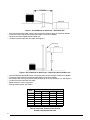
• Increaserestrictorbore0.001inchesiftotalequivalenthorizontallengthismorethan100feet.
• Crankcaseheaterrequirediftotalequivalentlengthismorethan100feet.
• Vaporlineshouldbeslopedtowardsindoorunit.
• 175feetmaximumequivalentlinelength.SeeFigure1.
Figure 1. Air Conditioner or Heat Pump – Horizontal Run
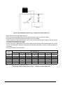
• IncreaseRestrictorbore0.001inchesiftotalequivalenthorizontallengthismorethan100feet.
• Crankcaseheaterrequirediftotalequivalentlengthismorethan100feet.
• Aninvertedvaporlinetrapmustbeinstalledwiththetopofthetrapabovetheunit.SeeFigure2.
• 175feetmaximumequivalentlinelength.
• 50feetmaximumverticalseparation.
• Changeoutdoorpiston.SeeTable8.
Figure 2. Air Conditioner or Heat Pump – Indoor Unit above Outdoor Unit
Btuh
Vertical Separation (ft)
0-20 21-30 31-40 41-50
18,000 0 -1 -1 -2
24,000 0 -1 -1 -2
30,000 0 -1 -1 -2
36,000 0 -1 -2 -2
42,000 0 -1 -2 -2
48,000 0 -1 -2 -2
60,000 0 -1 -2 -3
Table 8. Heat Pump Outdoor Piston Change
Outdoor Unit Below Indoor Unit

11
• Adjustrestrictorsize(s).SeeTable6(page4).
• Increaserestrictorbore0.001inchesiftotalhorizontalequivalentlengthismorethan100feet.
• Crankcaseheaterrequirediftotalequivalentlengthismorethan100feet.
• Ifverticalseparationisgreaterthan50feet,installavaporlineoiltrap50feetaboveindoorunitandevery40feet
up to outdoor unit elevation. See Figure 3.
• 175feetmaximumequivalentlinelength.
• Ifverticalseparationisgreaterthan75feet,installaliquidlinesolenoidvalvewithin10feetofoutdoorunit.Ahard
start kit is also required for single phase reciprocating compressor applications. An ASCT is recommended for air
conditioners.
• Changetheoutdoorpiston.SeeTable9.
Figure 3. Air Conditioner Or Heat Pump – Outdoor Unit Above Indoor Unit
Btuh
Vertical Separation (ft)
20-25 26-50 51-75 76-100 101-125 126-150 151-175
18,000 +1 +1 +2 +3 +3 +4 +5
24,000 +1 +1 +2 +3 +4 +5 +6
30,000 +1 +2 +2 +4 +5 +6 +8
36,000 +1 +2 +2 +4 +5 +6 +8
42,000 +1 +2 +3 +4 +5 +7 +8
48,000 +1 +2 +3 +4 +5 +7 +9
60,000 +1 +2 +3 +5 +6 +8 +10
NOTE:IfunitisequippedwithaTXV,nochangeisrequired
Table 9 Heat Pump Outdoor Piston Change – Outdoor Unit Above Indoor Unit

INSTALLER: PLEASE LEAVE THESE
INSTRUCTIONS WITH THE OWNER.
709299A (Replaces 7092990)
Specifications & illustrations subject to change without notice or incurring obligations (07/15).
O’Fallon, MO, © Nortek Global HVAC LLC 2015. All Rights Reserved.
-
 1
1
-
 2
2
-
 3
3
-
 4
4
-
 5
5
-
 6
6
-
 7
7
-
 8
8
-
 9
9
-
 10
10
-
 11
11
-
 12
12


Ask a question and I''ll find the answer in the document
Finding information in a document is now easier with AI
Related papers
-
Westinghouse FT4BE User guide
-
Broan Guideline for Refrigerant Lines Over 75 feet Installation guide
-
Westinghouse FT4BE User guide
-
Westinghouse FS4BD-KA/B Installation guide
-
-
Broan NS6BD-KA Installation guide
-
Broan JS5BD-024 User manual
-
-
Broan PSA2BD-KA Installation guide
-
Westinghouse MT4(B,Q)D Archived 11/21/2011 Installation guide
Other documents
-
Bryant 224ANS User guide
-
Rheem RA1460AD1NB Installation guide
-
Panasonic S-07MD1U6 Quick start guide
-
Durastar DRAC14A24WJ1NA Installation guide
-
-
-
 Heatcraft Refrigeration System Operating instructions
-
 Heat Controller SDAH 48 Installation Instructions Manual
-
EMI S2HA User manual
-
Bryant 114C User guide

