
Outdoor Heat Pump
13 SEER High Effi ciency Split System
User’s Information/Installation Instructions
These units have been designed and tested for capacity and effi ciency in accordance with A.R.I.
Standards. Split System Heat Pump units are designed for use with a wide variety of fossil fuel
furnaces, electric furnaces, air handlers, and evaporator coil combinations.
These instructions are primarily intended to assist qualifi ed individuals experienced in the proper
installation of heating and/or air conditioning appliances. Some local codes require licensed
installation/service personnel for this type of equipment. Read all instructions carefully before
starting the installation.
IMPORTANT
Read this owner information to become familiar with the capabilities and use of your appliance.
Keep this with literature on other appliances where you have easy access to it in the future. If a
problem occurs, check the instructions and follow recommendations given. If these suggestions
don’t eliminate your problem, call your servicing contractor.
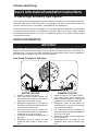
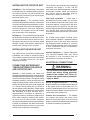
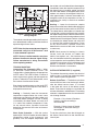
Heat Pump Principle of Operation
USER’S INFORMATION
5
4
1
2
3
6
5
4
3
2
1
6
SUMMER COOLING
1. Indoor air enters the air handler section.
2. Cold, heat-transfer section (indoor coil)
extracts heat from indoor air as refrigerant
evaporates from a liquid to a cold gas.
3. Refrigerant, drawn to heat pump and
compressed to a hot gas by heat pump,
carries the heat outdoors.
4. Hot, heat-transfer section (outdoor coil)
releases the heat as refrigerant condenses
from a gas to a liquid.
5. Heat pump (outdoor fan) discharges the
heat to outside air.
6. Refrigerant returns to indoor coil and
evaporates once again to absorb more
heat.
WINTER HEATING
1. Outdoor air enters heat pump.
2. Cold, heat-transfer section (outdoor coil)
extracts heat from outdoor air as refrigerant
evaporates from a liquid to a gas.
3. Refrigerant, compressed to a hot gas by
heat pump, carries the heat to the hot heat-
transfer section (indoor coil).
4. Hot, heat-transfer section (indoor coil)
releases the heat to indoor air as refrigerant
condenses from a gas to a liquid.
5. Air handler circulates the heat throughout
the home.
6. Refrigerant returns to outdoor coil and
evaporates once again to absorb more
heat.

2
2. Set the thermostat temperature to the
desired temperature level using the
temperature selector. Please refer to
the separate detailed thermostat user’s
manual for complete instructions regarding
thermostat programming. The outdoor unit
and indoor blower will both cycle on and off
to maintain the indoor temperature at the
desired heating level.
NOTE: If the thermostat temperature level is
re-adjusted, or the thermostat system switch
is repositioned, the outdoor unit may not
start immediately. The outdoor unit contains
a protective timer circuit which holds the unit
off for approximately fi ve minutes following
a previous operation, or the interruption of
the main electrical power.
Emergency Heat:
The thermostat includes a system switch
position termed EM. HT. This is a back-up
heating mode to be used only if there is a
suspected problem with the outdoor unit. With
the system switch set to EM. HT. the outdoor
unit will be locked off, and supplemental heat
(typically electric resistance heating) will be
used as a source of heat. Sustained use of
electric resistance heat in place of the heat
pump will result in an increase in electric
utility costs.
Defrost:
During cold weather heating operation, the
outdoor unit will develop a coating of snow
and ice on the heat transfer coil. This is
normal, and the unit will periodically defrost
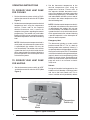
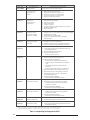
Figure 1. Typical Thermostat
OPERATING INSTRUCTIONS
TO OPERATE YOUR HEAT PUMP
FOR COOLING
1. Set the thermostat system switch to COOL
and the thermostat fan switch to AUTO. (See
Figure 1)
2. Set the thermostat temperature to the desired
temperature level using the temperature
selector. Please refer to the separate
detailed thermostat user’s manual for
complete instructions regarding thermostat
programming. The outdoor unit and indoor
blower will both cycle on and off to maintain
the indoor temperature at the desired cooling
level.
NOTE: If the thermostat temperature level is
re-adjusted, or the thermostat system switch
is repositioned, the outdoor unit may not
start immediately. The outdoor unit contains
a protective timer circuit which holds the unit
off for approximately fi ve minutes following a
previous operation, or the interruption of the
main electrical power.
TO OPERATE YOUR HEAT PUMP
FOR HEATING
1. Set the thermostat system switch to HEAT
and the thermostat fan switch to AUTO. (See
Figure 1)
System
Mode
Fan
Mode
Temperature
Selector(s)

3
TO MAINTAIN YOUR HEAT PUMP
CAUTION:
Be certain the electrical power to
the outdoor unit and the furnace/air
handler is disconnected before
doing the following recommended
maintenance.
1. Regularly:
a. Clean or replace the indoor air fi lter at the
start of each heating and cooling season,
and when an accumulation of dust and
dirt is visible on the air fi lter. Inspect the
fi lter monthly.
b. Remove any leaves and grass clippings
from the coil in the outdoor unit, being
careful not to damage the aluminum
fi n s .
c. Check for any obstruction such as twigs,
sticks, etc.
d. Certain models have external panels
fabricated from a premium grade of
stainless steel designed to inhibit
corrosion. For such units, if the unit is
located in a coastal region or other area
subjected to high concentrations of salt,
then the unit should be hosed off after
storms and monthly otherwise to maintain
its new appearance.
CAUTION:
Do not over-oil, or oil motors not
factory-equipped with oil tubes. The
compressor is hermetically “sealed”
and does not require lubrication.
2. Before Calling a Service Technician, Be
Certain:
a. The unit thermostat is properly set—see
“To Operate Your Heat Pump for Cooling”
and “To Operate Your Heat Pump for
Heating.”
b. The unit disconnect fuses are in good
condition, and the electrical power to the
unit is turned on.
itself. During the defrost cycle, the outdoor fan
will stop, and the compressor will continue
to run and heat the outdoor coil, causing the
snow and ice to melt. After the snow and ice
have melted, some steam may rise from the
outdoor unit as the warm coil causes some
melted frost to evaporate.
TO OPERATE YOUR HEAT PUMP
FOR AUTOMATIC COOLING AND
HEATING
1. Set the thermostat system switch to AUTO
and the thermostat fan switch to AUTO. (See
Figure 1)
Note: Thermostats will vary. Some models
will not include the AUTO mode, and others
will have the AUTO in place of the HEAT and
COOL, and some will include all three.
2. Set the thermostat temperature to the
desired heating and cooling temperature
level(s). The outdoor unit and the indoor
blower will then cycle on and off in either
the heating or cooling mode of operation as
required to automatically maintain the indoor
temperature within the desired limits.
TO SHUT OFF YOUR HEAT PUMP
Set the thermostat system switch to OFF and the
thermostat fan switch to AUTO. (See Figure 1)
The system will not operate, regardless of the
thermostat temperature selector(s) setting.
TO OPERATE THE INDOOR BLOWER
CONTINUOUSLY
Set the thermostat fan switch to ON (See Figure
1). The indoor blower will start immediately, and
will run continually until the fan switch is reset
to AUTO.
The continuous indoor blower operation can be
obtained with the thermostat system switch set
in any position, including OFF.
The continuous indoor blower operation is
typically used to circulate the indoor air to
equalize a temperature unbalance due to a sun
load, cooking, or fi replace operation.

4
Read Your Warranty
Please read the separate warranty document
completely. It contains valuable information
about your system.
GENERAL INFORMATION
Read the following instructions completely before
performing the installation.
Outdoor Unit Section — Each outdoor unit
is shipped with a refrigerant charge adequate
to operate the outdoor section with an indoor
matching coil or air handler. Units with braze
connections include the proper amount of
refrigerant for an additional 15 ft. of refrigerant
lines the same size as the valve fi ttings.
NOTE: DO NOT USE ANY PORTION OF
THE CHARGE FOR PURGING OR LEAK
TESTING.
Matching coils and air handlers may be shipped
with a small holding charge to pressurize them to
keep out contaminants. To release the pressure,
read the indoor section installation instructions
carefully.
Liquid and Suction Lines — Fully annealed,
refrigerant grade copper tubing should be used
when installing the system. Refrigerant suction
line tubing should be fully insulated.
Field Connections for Electrical Power
Supply — All wiring must comply with current
provisions of the “National Electrical Code”
(ANSI/NFPA 70) and with applicable local
codes having jurisdiction. The minimum size of
electrical conductors and circuit protection must
be in compliance with information listed on the
outdoor unit data label.
SAFETY CONSIDERATIONS
Pressures within the System — Split
system heat pump equipment contains liquid
and gaseous refrigerant under pressure.
Installation and servicing of this equipment
should be accomplished by qualifi ed, trained
personnel thoroughly familiar with this type of
equipment. Under no circumstances should the
Homeowner attempt to install and/or service
the equipment.
Labels, Tags, Precautions — When working
with this equipment, follow all precautions in the
literature, on tags, and on labels provided with
the equipment. Read and thoroughly understand
the instructions provided with the equipment prior
to performing the installation and operational
checkout of the equipment.
Brazing Operations — Installation of equipment
may require brazing operations. Safety codes
must be complied with. Safety equipment (e.g.;
safety glasses, work gloves, fi re extinguisher,
etc.) must be used when performing brazing
operations.
WARNING:
Ensure all electrical power to the unit
is off prior to installing or servicing the
equipment. Failure to do so may cause
personal injury or death.
SITE PREPARATION
Unpacking Equipment — Remove the
cardboard carton and User’s Manual from the
equipment. Take care to not damage tubing
connections when removing from the carton.
Inspect for Damage — Inspect the equipment
for damage prior to installing the equipment at
the job site. Ensure coil fi ns are straight and, if
necessary, comb fi ns to remove fl attened and
bent fi ns.
Preferred Location of the Outdoor Unit at the
Job Site — Conduct a survey of the job site to
determine the optimum location for mounting
the outdoor unit. Overhead obstructions,
poorly ventilated areas, and areas subject to
accumulation of debris should be avoided. The
outdoor unit should be installed no closer than
18 inches from the outside walls of the facility
and in an area free from overhead obstructions
to ensure unrestricted airflow through the
outdoor unit.
Facility Prerequisites — Electrical power
supplied must be adequate for proper operation
of the equipment. The system must be wired and
provided with circuit protection in accordance
with local building codes and the National
Electrical Code.

5
The maximum recommended interconnecting
refrigerant line length is 75 feet, and the
vertical elevation difference between the indoor
and outdoor sections should not exceed 20
feet. Consult long line application guide for
installations in excess of these limits.
Filter Dryer Installation — A fi lter dryer is
provided with PS series models only and must
be installed in the liquid line of the system. If the
installation replaces a system with a fi lter dryer
already present in the liquid line, the fi lter dryer
must be replaced with the one supplied with the
unit. The fi lter dryer must be installed in strict
accordance with the manufacturer’s installation
instructions.
For all other series models, installing a fi lter
dryer is optional. However, it is good installation
practice to install a fi lter dryer when replacing
the evaporator and/or condenser of a system.
When installing, the fi lter dryer must be installed
in strict accordance with the manufacturer’s
installation instructions.
Optional Equipment — Optional equipment
(e.g.: liquid line solenoid valves, etc.) should
be installed in strict accordance with the
manufacturer’s installation instructions.
ELECTRICAL CONNECTIONS
WARNING:
Turn off all electrical power at the main
circuit box before wiring electrical
power to the outdoor unit. Failure to
comply may cause severe personnel
injury or death.
Wiring Diagram/Schematic — A wiring
diagram/schematic is located on the inside cover
of the electrical box of the outdoor unit. The
installer should become familiar with the wiring
diagram/schematic before making any electrical
connections to the outdoor unit.
Outdoor Unit Connections — The outdoor
unit requires both power and control circuit
electrical connections. Refer to the unit wiring
diagram/schematic for identifi cation and location
of outdoor unit fi eld wiring interfaces.
INSTALLING THE OUTDOOR UNIT
Slab Mount — The site selected for a slab mount
installation requires a stable foundation and one
not subject to erosion. The slab should be level
and anchored (if necessary) prior to placing the
equipment on the slab.
Cantilever Mount — The cantilever mount
should be designed with adequate safety factor
to support the weight of the equipment, and for
loads subjected to the mount during operation.
Installed equipment should be adequately
secured to the cantilever mount and levelled
prior to operation of the equipment.
Roof Mount — The method of mounting should
be designed so as not to overload roof structures
nor transmit noise to the interior of the structure.
Refrigerant and electrical line should be routed
through suitably waterproofed openings to
prevent water leaking into the structure.
INSTALLING THE INDOOR UNIT
The indoor section should be installed before
proceeding with routing of refrigerant piping.
Consult the Installation Instructions of the indoor
unit (i.e.: air handler, furnace, etc.) for details
regarding installation.
CONNECTING REFRIGERANT
TUBING BETWEEN THE INDOOR
AND OUTDOOR UNIT
General — Once outdoor and indoor unit
placement has been determined, route refrigerant
tubing between the equipment in accordance with
sound installation practices. Refrigerant tubing
should be routed in a manner that minimizes the
length of tubing and the number of bends in the
tubing. Refrigerant tubing should be supported
in a manner that the tubing will not vibrate or
abrade during system operation. Tubing should
be kept clean of foreign debris during installation
and installation of a liquid line fi lter drier is
recommended if cleanliness or adequacy of
system evacuation is unknown or compromised.
Every effort should be made by the installer
to ensure that the fi eld installed, refrigerant
containing components of the system have been
installed in accordance with these instructions
and sound installation practices so as to insure
reliable system operation and longevity.

6
Control Circuit Wiring — The outdoor unit is
designed to operate from a 24 VAC Class II control
circuit. Control circuit wiring must comply with
the current provisions of the “National Electrical
Code” (ANSI/NFPA 70) and with applicable local
codes having jurisdiction.
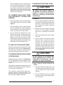
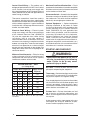
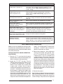
Thermostat connections should be made in
accordance with the instructions supplied with
the thermostat, and with the instructions supplied
with the indoor equipment. A typical residential
installation with a heat pump thermostat and air
handler are shown below.
Electrical Power Wiring — Electrical power
wiring must comply with the current provisions
of the “National Electrical Code” (ANSI/NFPA
70) and with applicable local codes having
jurisdiction. Use of rain tight conduit is
recommended. Electrical conductors shall have
minimum circuit ampacity in compliance with the
outdoor unit rating label. The facility shall employ
electrical circuit protection at a current rating no
greater than that indicated on the outdoor unit
rating label. Refer to the unit wiring diagram for
connection details.
Minimum Circuit Ampacity — Electrical wiring
to the equipment must be compatible and in
compliance with the minimum circuit ampacity
listed on the outdoor unit data label.
Maximum Fuse/Circuit Breaker Size — Circuit
protection for the outdoor unit must be compatible
with the maximum fuse/circuit breaker size listed
on the outdoor unit data label.
Disconnect Switch — An electrically compatible
disconnect switch must be within line of sight of
the outdoor unit. This switch shall be capable of
electrically de-energizing the outdoor unit.
Optional Equipment — Optional equipment
requiring connection to the power or control
circuits must be wired in strict accordance with
current provisions of the “National Electrical
Code” (ANSI/NFPA 70), with applicable local
codes having jurisdiction, and the installation
instructions provided with the equipment.
Optional Equipment (e.g.: liquid line solenoid
valves, hard start kits, low suction pressure
cutout switch kit, high pressure cutout switch kit,
refrigerant compressor crankcase heater, etc.)
should be installed in strict accordance with the
manufacturer’s installation instructions.
STARTUP AND CHECKOUT
WARNING:
Ensure electrical power to the unit is
off prior to performing the following
steps. Failure to do so may cause
personal injury or death.
Air Filters — Ensure air fi lters are clean and in
place prior to operating the equipment.
Thermostat — Set the room thermostat function
switch to OFF, fan switch to AUTO, and adjust the
temperature setpoint to its highest setting.
Prior to applying electrical power to the outdoor
unit, ensure that the unit has been properly and
securely grounded, and that power supply
connections have been made at both the facility
power interface and outdoor unit.
Outdoor Unit — Ensure the outdoor coil and
top of the unit are free from obstructions and
debris, and all equipment access/control panels
are in place.
Using extreme caution, apply power to the unit
and inspect the wiring for evidence of open,
shorted, and/or improperly wired circuits.
Wire Size based on N.E.C. for 60° type copper
conductors.
COPPER WIRE SIZE — AWG
(1% Voltage Drop)
Supply Wire Length-Feet Supply Circuit
200 150 100 50 Ampacity
6 8 10 14 15
46812 20
46810 25
44610 30
3468 35
3468 40
2346 45
2346 50

7
GRW
2
CEOY
Thermostat
Green
Red
Brown
G
R
W
2
Orange
Black
OY
R
C
Air Handler Heat Pump OD
Section
Typical Heat Pump with Standard Air Handler
W
2
C
W
NOTE: Jumper
between W2 and E is
required when no OD
T-Stat is used.
For 2-Stage
Heater
Kits
A typical installation with a heat pump thermostat, air handler, and heat pump with an outdoor
thermostat.
GRW
2
CEOY
Thermostat
Green
Red
White
G
R
Black
O Y
R
C
Air Handler Heat Pump OD
Section
Typical Heat Pump with
Outdoor Thermostat and Air Handler
W
2
C
W
E

8
Functional Checkout:
CAUTION:
If equipped with a compressor
crankcase heater, wait 24 hours prior
to performing a function checkout to
allow for heating of the compressor
crankcase. Failure to comply may
result in damage and could cause
premature failure of the system.
Indoor Blower — Set the thermostat function
switch to COOLING and the fan switch to ON.
Verify that the indoor blower is operating and
that airfl ow is not restricted. Set the fan switch
back to AUTO.
Positive Temperature Coeffi cient Resistor
(PTCR) — (select models) A PTCR is factory
installed and located on the control panel of the
outdoor unit. The PTCR is a soft start device for
use with reciprocating compressors. If a hard
start kit is needed on this model the soft start
(PTCR) must be removed fi rst.
Low-Pressure Switch — A low-pressure
switch is factory-installed in select models only.
If provided, this switch is located in the suction
line internal to the outdoor unit. The switch is
designed to protect the compressor from a loss
of charge. Under normal conditions, the switch
is closed. If the suction pressure falls below 5
psig, then the switch will open and de-energize
the outdoor unit. The switch will close again
once the suction pressure increases above 20
psig. Please note that the switch interrupts the
thermostat inputs to the unit. Thus, when the
switch opens and then closes, there will be a 5
minute short cycling delay before the outdoor
unit will energize.
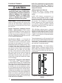
Comfort Alert
TM
Diagnostics (Select Models)
— The Comfort Alert
TM
diagnostics module is
a breakthrough innovation for troubleshooting
heat pump and air conditioning system failures.
The module installs easily in the electric box of
the outdoor unit near the compressor contac-
tor. By monitoring and analyzing data from the
Copeland Scroll compressor
®
and the thermo-
stat demand, the module can accurately detect
the cause of electrical and system related failures
without any sensors. A fl ashing LED indicator
communicates the ALERT code and guides the
service technician more quickly and accurately
to the root cause of a problem.
NOTE: This module does not provide safety
protection! The Comfort Alert
TM
module is a
monitoring device and cannot shut down the
compressor directly.
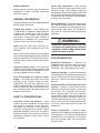
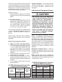
LED Description (See Figure 2)
POWER LED (Green): indicates voltage
is present at the power connection of the
module.
ALERT LED (Yellow): communicates an
abnormal system condition through a unique
fl ash code. The ALERT LED will fl ash a number
of times consecutively, pause and then repeat
the process. The number of consecutive
fl ashes, defi ned as the Flash Code, correlates
to a particular abnormal condition. Detailed
descriptions of specifi c ALERT Flash Codes are
shown in Table 1 of this manual.
TRIP LED (Red): indicates there is a demand
signal from the thermostat but no current to the
compressor is detected by the module. The TRIP
LED typically indicates the compressor protector
is open or may indicate missing supply power
to the compressor.
The scroll compressor’s run (R), common (C) and
start (S) wires are routed through the holes in the
Comfort Alert
TM
module marked “R,” “C” and “S.”
The common (C) wire need not be routed through
the module for it to operate properly.
24 VAC Power Wiring — The Comfort Alert
TM
module requires a constant nominal 24 VAC
power supply. The wiring to the module’s R and
C terminals must be directly from the indoor unit
or thermostat.
Figure 2. Comfort Alert
TM
Diagnostics
Module
POWER
ALERT
TRIP

9
The module cannot be powered by the C terminal
on a defrost board or other control board without
experiencing nuisance alerts.
NOTE: After the thermostat demand signal is
connected, verify that 24 VAC across Y and
C when demand is present.
NOTE: Factory installed modules may have
different thermostat demand signal wiring.
Follow manufacturer’s wiring instructions
when replacing module.
TROUBLESHOOTING
Interpreting The Diagnostic LEDs – When
an abnormal system condition occurs, the
Comfort Alert
TM
module displays the appropriate
ALERT and/or TRIP LED will fl ash a number of
times consecutively, pause and then repeat the
process. To identify a Flash Code number, count
the number of consecutive fl ashes.
Every time the module powers up, the last ALERT
Flash Code that occurred prior to shut down is
displayed for one minute.
Cooling — Gradually lower the thermostat
temperature setpoint below the actual room
temperature and observe that the outdoor unit
and indoor blower energize. Feel the air being
circulated by the indoor blower and verify that
it is cooler than ambient temperature. Listen
for any unusual noises. If present, locate and
determine the source of the noise and correct
as necessary.
Short Cycle Protection — With the system
operating in COOLING mode, note the setpoint
temperature setting of the thermostat, and
gradually raise the setpoint temperature until
the outdoor unit and indoor blower de-energize.
Immediately lower the setpoint temperature of
the thermostat to its original setting and verify
that the indoor blower is energized and that the
outdoor unit remains de-energized. Verify that,
after approximately 5 minutes, the outdoor unit
energizes and that the temperature of the air
supplied to the facility is cooler than ambient
temperature.
Heating — Lower the thermostat setpoint
temperature to the lowest obtainable setting and
set the thermostat function switch to HEATING.
The indoor blower and outdoor unit should stop
running. After a minimum of fi ve minutes, increase
the setpoint temperature of the thermostat to the
maximum setting. Verify that the outdoor unit and
indoor blower have energized. Feel the air being
circulated by the indoor blower and verify that
it is warmer than ambient temperature. Listen
for any unusual noises. If present, locate and
determine the source of the noise and correct
as necessary.
NOTE: Other sources for heating (i.e.: electric
furnace, fossil fuel furnace, air handler with
electric heat options, etc.) that interface with
the unit should be functionally checked to verify
system operation and compatibility. Refer to the
installation instructions for this equipment and
perform a functional checkout in accordance
with the manufacturer’s instructions.
OUTDOOR THERMOSTAT (if supplied)
The outdoor thermostat prevents the electrical
auxiliary heat (if used) from operating above
40°F outdoor ambient temperature.
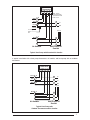
Defrost Cycle Timer — The defrost cycle timer
controls the time interval of the hot gas defrost
after the defrost sensor closes. It is located
in the lower left corner of the defrost control
board. Three interval settings are available: 30
minutes, 60 minutes, and 90 minutes. Time setting
selection is dependent on the climate where the
unit is being installed.
Example 1. Dry climate of Southern
Arizona. A 90 minute setting is
recommended.
Example 2. Moist climate of Seattle,
Washington. A 30 minute setting is
recommended.
To set the cycle timer, place the timing pin on
the defrost control board to the desired time
interval post.
Low Voltage
Terminals
E
Defrost Control Board
DFT
Control
Logic
DF1
DF2
DFT
1
2
3
4
1
R
W2
O
Y
C
T2
T1
R
W2
O
Y
C
RVS
HPS
LPS
L
C
R
Comfort
Alert
CC
L
Y
L
Figure 3. 24VAC Comfort Alert
TM
Wiring Diagram

10
Table 1. Interpreting the Diagnostic LEDS
Status LED Status LED Description Status LED Troubleshooting Information
Green “POWER” Module has power Supply voltage is present at module terminals
Red “TRIP” Thermostat demand signal
1. Compressor protector is open
Y is present, but the
2. Outdoor unit power disconnect is open
compressor is not
3. Compressor circuit breaker or fuse(s) is open
running
4. Broken wire or connector is not making contact
5. Low pressure switch open if present in system
6. Compressor contactor has failed open
Yellow “ALERT” Long Run Time 1. Low refrigerant charge
Flash Code 1 Compressor is 2. Evaporator blower is not running
running extremely 3. Evaporator coil is frozen
long run cycles 4. Faulty metering device
5. Condenser coil is dirty
6. Liquid line restriction (filter drier blocked if present in system)
7. Thermostat is malfunctioning
8. Comfort Alert Failure
Yellow “ALERT” System Pressure Trip
1. High head pressure
Flash Code 2 Discharge or suction
2. Condenser coil poor air circulation (dirty, blocked, damaged)
pressure out of limits or
3. Condenser fan is not running
compressor overloaded
4. Return air duct has substantial leakage
5. If low pressure switch present in system, check Flash
Code 1 information
Yellow “ALERT” Short Cycling 1. Thermostat demand signal is intermittent
Flash Code 3 Compressor is running 2. Time delay relay or control board defective
only briefly 3. If high pressure switch present go to Flash Code 2 information
4. If low pressure switch present go to Flash Code 1 information
Yellow “ALERT” Locked Rotor
1. Run capacitor has failed
Flash Code 4
2. Low line voltage (contact utility if voltage at disconnect is low)
• Check wiring connections
3. Excessive liquid refrigerant in compressor
4. Compressor bearings are seized
• Measure compressor oil level
Yellow “ALERT” Open Circuit
1. Outdoor unit power disconnect is open
Flash Code 5
2. Compressor circuit breaker or fuse(s) is open
3. Compressor contactor has failed open
• Check compressor contactor wiring and connectors
• Check for compressor contactor failure (burned, pitted or
open)
• Check wiring and connectors between supply and
compressor
• Check for low pilot voltage at compressor contactor coil
4. High pressure switch is open and requires manual reset
5. Open circuit in compressor supply wiring or connections
6. Unusually long compressor protector reset time due to
extreme ambient temperature
7. Compressor windings are damaged
• Check compressor motor winding resistance
Yellow “ALERT” Open Start Circuit 1. Run capacitor has failed
Flash Code 6 Current only in run circuit 2. Open circuit in compressor start wiring or connections
• Check wiring and connectors between supply and the
compressor “S” terminal
3. Compressor start winding is damaged
• Check compressor motor winding resistance
Yellow “ALERT” Open Run Circuit 1. Open circuit in compressor run wiring or connections
Flash Code 7 Current only in start circuit • Check wiring and connectors between supply and the
compressor “R” terminal
2. Compressor run winding is damaged
• Check compressor motor winding resistance
Yellow “ALERT” Welded Contactor 1. Compressor contactor has failed closed
Flash Code 8 Compressor always runs 2. Thermostat demand signal not connected to module
Yellow “ALERT” Low Voltage 1. Control circuit transformer is overloaded
Flash Code 9 Control circuit < 17VAC 2. Low line voltage (contact utility if voltage at disconnect is low)
• Check wiring connections
•
Flash Code number corresponds to a number of LED flashes, followed by a pause and then repeated.
•
TRIP and ALERT LEDs flashing at same time means control circuit voltage is too low for operation.

11
Table 2. Module Wiring Troubleshooting
Miswired Module Indication Recommended Troubleshooting Action
Green LED is not on, Determine if both R and C module terminals are
module does not power up connected. Verify voltage is present at module’s R and
C terminals. Review 24VAC Power Wiring (page 4) for
R and C wiring.
Green LED intermittent, Determine if R and Y terminals are wired in reverse.
module powers up only Verify module’s R and C terminals have a constant
when compressor runs source. Review 24VAC Power Wiring (page 4) for R
and C wiring.
TRIP LED is on but system Verify Y terminal is connected to 24VAC at contactor
and compressor check OK coil. Verify voltage at contactor coil falls below 0.5VAC
when off.
TRIP LED and ALERT LED Verify R and C terminals are supplied with 19-28VAC.
flashing together
ALERT Flash Code 3 Verify Y terminal is connected to 24VAC at contactor coil.
(Compressor Short Cycling) Verify voltage at contactor coil falls below 0.5VAC when
displayed incorrectly off.
ALERT Flash Code 5, 6 or 7 Check that compressor run and start wires are through
(Open Circuit, Open Start Circuit module’s current sensing holes. Verify Y terminal is
or Open Run Circuit) displayed connected to 24VAC at contactor coil. Verify voltage at
incorrectly contactor coil falls below 0.5VAC when off.
ALERT Flash Code 6 (Open Check that compressor run and start wires are routed
Start Circuit) displayed for Code 7 through the correct module sensing holes.
(Open Run Circuit) or vice versa
ALERT Flash Code 8 Determine if module’s Y terminal is connected. Verify Y
(Welded Contactor) terminal is connected to 24VAC at contactor coil. Verify
displayed incorrectly 24VAC is present across Y and C when thermostat demand
signal is present. If not, R and C are reverse wired. V erify
voltage at contactor coil falls below 0.5VAC when off.
Note: All units are shipped from the factory with
the default time setting of 30 minutes. Maximum
heating performance can be achieved by setting
the time to 90 minutes.
DEFROST CONTROL BOARD OPERATION
AND TESTING
1. Terminals “R”-”C” must have 24±V present
between them in order for the time delay and
defrost sequences to be operational.
2. Jumper the “T2”-”DFT” test pins. This will
indicate to the board that the defrost T-stat
is closed(if the compressor is running).
Defrost T-stat is closed at 32° or below and
is open at 68° or above. But it’s state is
unknown if the temperature is between 32°F
and 68°F. The defrost thermostat tells the
board whether a defrost cycle needs to be
started or terminated. With the DFT closed
the unit will run for 30/60/90 minutes in heat
mode and then defrost the outdoor coil. The
defrost will turn off the outdoor fan, turn on the
compressor and raise the the coil temperature
to 68°F. This will open the DFT and terminate
the defrost. If the DFT does not open the
defrost will end after 10 minutes.
3. Defrost board speed-up. With compressor
running in heat mode, next jump the “Test”
pin to “C” on terminal strip. This will initiate
a defrost test in 5, 10 or 15 seconds (This
is determined by the 30, 60 or 90 minute
defrost pin settings. The factory setting will
be 30 minutes). Note that this will bypass the
compressor off delay when the unit goes into
defrost test and if left in defrost test, the delay
will be bypassed when the test is terminated
by the processor. If the jumper is removed
before the test is over the processor will
perform the remainder of a normal defrost.
See step 2 above.
4. Remove the jumpers.
Note: The delay/no-delay pin concerns compressor
operation during defrosts. The default setting is
delay. Reciprocating compressors should only
use this setting in conjunction with an approved

12
hard start kit. Scroll compressors that have noise
issues while going into or coming out of defrost
should use this 30 second delay to reduce the
defrost noise. To switch from no-delay to delay
remove the pin from the “no-delay” pin location
and shift it to the “delay” pin location.
Speed up changes:
Manually initiating a defrost will cause the
compressor to run continually when entering
defrost.
Normal defrost operation:
To test normal defrost operation when the
temperature is above 35°F, jumper “R” to
“DFT” on the 624656 board and allow the unit
to run for 30 minutes. Defrost will continue
until the “R” to “DFT” jumper is removed or
for 10 minutes. Remove the jumper.
The 5 minute time delay feature can be shortened
1 time to 1 second by jumping the “Test” to “C”
terminal. Remove the jumper and repeat as
desired.
Note: If jumper is left on the “Test” to “common”
pins permanently, the defrost cycle will become
inoperable.
Defrost Test Procedure for 624656
1. Jumper “T2” to “DFT” at the test terminals.
2. With unit running in heat mode, short the
“TEST” terminal to the common terminal near
it. This will speed up the board and cause
it to enter defrost mode in 5/10/15 seconds
depending on the defrost time selection.
Compressor delay will not function during
speed-up.
3. This test will end in 5 seconds if the “TEST”-
common short is not removed.
4. Remove both the short and the “T2” to “DFT”
jumper to terminate the defrost cycle. The
30 second compressor delay should operate
normally.
5. Test is complete, reset thermostat to home
owner preference.
13 SEER Split System Heat Pump Orifi ce
Usage with ZRK3/K4 Compressor
13 SEER Split System Heat Pump Orifi ce
Usage with CRK7 Compressor
Optional Equipment — A functional checkout
should be performed in accordance with
the checkout procedures supplied with the
equipment.
Adjustment of Refrigerant Charge:
CAUTION:
Split system heat pump equipment
contains liquid and gaseous refrigerant
under pressure. Adjustment of
refrigerant charge should only be
attempted by qualified, trained
personnel thoroughly familiar with the
equipment. Under no circumstances
should the homeowner attempt to
install and/or service this equipment.
Failure to comply with this warning
could result in equipment damage,
personal injury, or death.
NOTE: The following Refrigerant Charging
Charts are applicable to listed assemblies of
equipment and at listed airfl ows for the indoor
coil. Assemblies of indoor coils and outdoor units
not listed are not recommended and deviations
from rated airfl ows or non-listed equipment
combinations may require modifi cations to the
expansion device(s) and refrigerant charging
procedures for proper and effi cient system
operation.
Refrigerant Charging Chart — Refer to
Refrigerant Charging Charts for correct system
charging, and to Orifi ce Usage Chart for correct
restrictor sizes.
NOTE: Linesets over 15 feet in length may
require additional refrigerant charge. NORDYNE
recommends 0.6 oz. of refrigerant per foot for
any lineset over 15 feet.
Model
Number
Restrictor Bore Size (inches)
System
Charge
R2 (oz.)
Indoor Outdoor
1.5 ton 0.053 0.041 93
2.0 ton 0.061 0.047 96
2.5 ton 0.069 0.049 144
3.0 ton 0.078 0.057 155
3.5 ton 0.083 0.059 248
4.0 ton 0.090 0.065 248
5.0 ton 0.101 0.071 268
Model
Number
Restrictor Bore Size
(inches)
System
Charge R-22
(oz.)
Indoor Outdoor
2.0 Ton 0.061 0.049 126
2.5 Ton 0.068 0.049 144

13
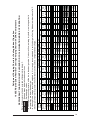
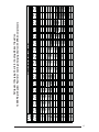
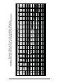
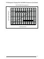
Refrigerant Charging Charts for Cooling Mode of Operation
13 SEER Split System Restrictor Cooling Charging Charts with ZRK4 Compressors
*Note: All pressures are listed in psig. and all temperatures in deg. F.
- Shaded boxes indicate fl ooded conditions
- Rated design values.
- In Cooling Mode suction pressure will be lower than design value if indoor air fl ow, entering dry bulb, or entering wet bulb
temperatures are lower than design.
- In Heating Mode, charge should be weighed in. It is strongly recommended to verify charge in Cooling Mode at ambient above 70°F.
- Discharge temperatures greater than charted values indicates a refrigerant undercharge.
REFRIGERANT CHARGING CHARTS LEGEND FOR COOLING/HEATING MODES OF OPERATION
Suction
Press.
Dis.
Press.
Dis.
Temp.
Dis.
Press.
Dis.
Temp.
Dis.
Press.
Dis.
Temp.
Dis.
Press.
Dis.
Temp.
Dis.
Press.
Dis.
Temp.
Dis.
Press.
Dis.
Temp.
Dis.
Press.
Dis.
Temp.
Dis.
Press.
Dis.
Temp.
73 140 135
75 143 140 155 137
77 145 146 157 143 170 140
79 147 150 160 148 172 145 185 142
81 151 153 162 152 175 150 187 147 200 144
83 166 155 177 154 189 151 202 149 215 147
85 181 157 192 155 204 153 217 151 230 149
87 196 159 207 157 219 155 232 153 244 151
89 199 163 211 161 222 159 234 157 246 154
91 214 165 226 163 237 161 248 158
93 229 167 241 165 252 163
95 244 169 256 167
97 259 172
99
70
75
80
85
90
95
100
105
1-1/2
TON
OUTDOOR TEMPERATURE (°F)

14
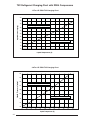
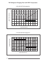
Refrigerant Charging Charts for Cooling Mode of Operation
13 SEER Split System Restrictor Cooling Charging Charts with ZRK4 Compressors
Suction
Press.
Dis.
Press.
Dis.
Temp.
Dis.
Press.
Dis.
Temp.
Dis.
Press.
Dis.
Temp.
Dis.
Press.
Dis.
Temp.
Dis.
Press.
Dis.
Temp.
Dis.
Press.
Dis.
Temp.
Dis.
Press.
Dis.
Temp.
Dis.
Press.
Dis.
Temp.
71 149 137
73 151 143 164 141
75 154 148 166 146 179 145
77 156 153 169 151 181 150 194 149
79 160 155 171 156 184 155 196 153 209 152
81 175 159 186 159 198 158 211 157 224 156
83 190 162 202 162 213 161 226 160 239 160
85 205 166 217 165 228 164 241 164 254 163
87 208 169 220 169 232 168 243 168 256 167
89 224 173 235 173 247 172 258 171
91 239 177 250 176 262 175
93 254 180 265 180
95 269 184
97
90
95
100
105
2
TON
OUTDOOR TEMPERATURE (°F)
70
75
80
85

15
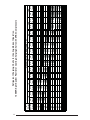
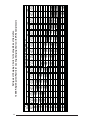
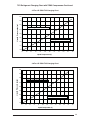
Refrigerant Charging Charts for Cooling Mode of Operation
13 SEER Split System Restrictor Cooling Charging Charts with ZRK3 Compressors
Suction
Press.
Dis.
Press.
Dis.
Temp.
Dis.
Press.
Dis.
Temp.
Dis.
Press.
Dis.
Temp.
Dis.
Press.
Dis.
Temp.
Dis.
Press.
Dis.
Temp.
Dis.
Press.
Dis.
Temp.
Dis.
Press.
Dis.
Temp.
Dis.
Press.
Dis.
Temp.
70 143 136
72 145 141 158 139
74 147 147 160 144 173 142
76 150 152 162 149 175 147 188 145
78 153 155 165 154 177 152 190 149 202 147
80 168 157 180 156 192 154 204 152 217 150
82 183 159 195 158 207 156 219 154 232 152
84 198 161 210 160 221 158 234 156 247 154
86 202 165 213 164 225 162 236 160 249 158
88 217 168 228 166 240 164 251 162
90 232 170 243 169 255 167
92 247 173 258 171
94 261 176
96
OUTDOOR TEMPERATURE (°F)
70
75
80
85
90
95
100
105
2-1/2
TON

16
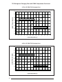
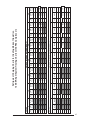
Refrigerant Charging Charts for Cooling Mode of Operation
13 SEER Split System Restrictor Cooling Charging Charts with ZRK3 Compressors
3
TON
Suction
Press.
Dis.
Press.
Dis.
Temp.
Dis.
Press.
Dis.
Temp.
Dis.
Press.
Dis.
Temp.
Dis.
Press.
Dis.
Temp.
Dis.
Press.
Dis.
Temp.
Dis.
Press.
Dis.
Temp.
Dis.
Press.
Dis.
Temp.
Dis.
Press.
Dis.
Temp.
71 148 144
73 150 149 164 147
75 152 155 166 152 179 149
77 155 158 168 157 181 154 195 152
79 159 161 171 161 183 159 197 156 210 154
81 174 164 187 163 199 161 212 158 226 156
83 190 166 202 165 214 163 228 161 241 159
85 206 168 218 167 230 165 243 163 257 161
87 209 172 221 171 233 169 245 167 259 165
89 225 174 237 173 249 171 261 169
91 240 177 252 175 264 173
93 256 180 268 178
95 271 182
97
OUTDOOR TEMPERATURE (°F)
70
75
80
85
90
95
100
105

17
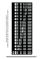
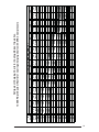
Refrigerant Charging Charts for Cooling Mode of Operation
13 SEER Split System Restrictor Cooling Charging Charts with ZRK3 Compressors
3-1/2
TON
Suction
Press.
Dis.
Press.
Dis.
Temp.
Dis.
Press.
Dis.
Temp.
Dis.
Press.
Dis.
Temp.
Dis.
Press.
Dis.
Temp.
Dis.
Press.
Dis.
Temp.
Dis.
Press.
Dis.
Temp.
Dis.
Press.
Dis.
Temp.
Dis.
Press.
Dis.
Temp.
71 144 150
73 146 155 159 152
75 148 161 161 157 175 153
77 152 163 164 162 177 158 191 154
79 155 165 167 164 179 163 193 159 206 156
81 171 167 183 166 195 164 208 160 222 157
83 186 169 198 167 210 165 224 162 237 159
85 202 171 214 169 226 166 239 163 253 160
87 205 174 217 172 229 170 241 167 255 164
89 221 176 233 174 245 171 257 168
91 236 178 248 175 260 172
93 252 180 264 177
95 267 181
97
OUTDOOR TEMPERATURE (°F)
70
75
80
85
90
95
100
105

18
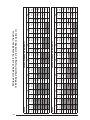
Refrigerant Charging Charts for Cooling Mode of Operation
13 SEER Split System Restrictor Cooling Charging Charts with ZRK3 Compressors
4
TON
Suct.
Press.
Dis.
Press.
Dis.
Temp.
Dis.
Press.
Dis.
Temp.
Dis.
Press.
Dis.
Temp.
Dis.
Press.
Dis.
Temp.
Dis.
Press.
Dis.
Temp.
Dis.
Press.
Dis.
Temp.
Dis.
Press.
Dis.
Temp.
Dis.
Press.
Dis.
Temp.
69 132 130
71 134 136 149 135
73 136 141 151 140 166 140
75 137 149 153 145 168 145 183 145
77 140 152 154 152 170 150 185 149 200 149
79 158 155 172 155 188 154 203 153 218 153
81 176 158 190 158 205 158 220 157 235 157
83 193 162 207 162 222 162 237 161 252 161
85 197 166 211 166 225 166 239 165 254 165
87 214 170 229 170 243 170 256 169
89 232 174 246 174 260 174
91 250 178 264 178
93 267 183
95
OUTDOOR TEMPERATURE (°F)
70
75
80
85
90
95
100
105

19
Refrigerant Charging Charts for Cooling Mode of Operation
13 SEER Split System Restrictor Cooling Charging Charts with ZRK3 Compressors
5
TON
Suct.
Press.
Dis.
Press.
Dis.
Temp.
Dis.
Press.
Dis.
Temp.
Dis.
Press.
Dis.
Temp.
Dis.
Press.
Dis.
Temp.
Dis.
Press.
Dis.
Temp.
Dis.
Press.
Dis.
Temp.
Dis.
Press.
Dis.
Temp.
Dis.
Press.
Dis.
Temp.
66 143 146
68 145 152 159 149
70 147 157 161 154 175 152
72 148 164 163 159 178 157 192 155
74 152 167 165 165 180 162 194 159 208 157
76 169 168 182 167 196 164 210 161 224 159
78 185 170 198 168 212 166 226 164 240 161
80 202 172 215 170 228 168 242 165 256 163
82 205 175 218 174 232 172 244 169 258 167
84 222 178 235 176 248 174 260 171
86 238 180 252 178 265 176
88 255 182 268 180
90 271 185
92
90
95
100
105
70
75
80
85
OUTDOOR TEMPERATURE (°F)

20
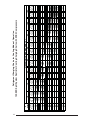
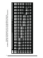
Refrigerant Charging Charts for Cooling Mode of Operation
13 SEER Split System Restrictor Cooling Charging Charts with CRK7 Compressors
Suct.
Press.
Dis.
Press.
Dis.
Temp.
Dis.
Press.
Dis.
Temp.
Dis.
Press.
Dis.
Temp.
Dis.
Press.
Dis.
Temp.
Dis.
Press.
Dis.
Temp.
Dis.
Press.
Dis.
Temp.
Dis.
Press.
Dis.
Temp.
Dis.
Press.
Dis.
Temp.
73 159 152
75 162 157 173 152
77 164 162 175 157 187 152
79 167 166 178 162 189 157 201 152
81 171 168 181 165 191 162 203 157 215 152
83 184 168 195 165 205 161 217 157 228 152
85 198 169 208 165 219 161 230 156 242 152
87 212 169 222 165 233 161 244 156 256 152
89 215 172 226 169 236 165 246 160 258 156
91 229 173 239 169 250 164 260 160
93 243 173 253 169 263 164
95 257 173 267 169
97 270 173
99
100
105
2
TON
OUTDOOR TEMPERATURE (°F)
70
75
80
85
90
95
Page is loading ...
Page is loading ...
Page is loading ...
Page is loading ...
Page is loading ...
Page is loading ...
Page is loading ...
Page is loading ...
Page is loading ...
Page is loading ...
Page is loading ...
Page is loading ...
-
 1
1
-
 2
2
-
 3
3
-
 4
4
-
 5
5
-
 6
6
-
 7
7
-
 8
8
-
 9
9
-
 10
10
-
 11
11
-
 12
12
-
 13
13
-
 14
14
-
 15
15
-
 16
16
-
 17
17
-
 18
18
-
 19
19
-
 20
20
-
 21
21
-
 22
22
-
 23
23
-
 24
24
-
 25
25
-
 26
26
-
 27
27
-
 28
28
-
 29
29
-
 30
30
-
 31
31
-
 32
32


Maytag PSH2BD Installation guide
- Type
- Installation guide
Ask a question and I''ll find the answer in the document
Finding information in a document is now easier with AI
Related papers
-
Broan DS5BD-KA/B Installation guide
-
Intertherm DS5(B,Q)D-KA Installation guide
-
Broan PSA2BD-KA Installation guide
-
Broan PSH4BF-KA/B Installation guide
-
Broan JT6BE Installation guide
-
Broan PSA4BF Installation guide
-
-
Broan FT4BE Installation guide
-
Maytag DT4(B,Q)D-K/KA Installation guide
-
Broan CSH4BE Installation guide