Page is loading ...

888-996-2729 - 1
1 3 5 3 - 3 7 8 - 6 6 8 - 1 : X A F
m o c . s t r o p s e d a l a c s e @ gameroom
y t i l a u q t s e h g i h e h t f o e r a s t c u d o r p r u o t a h t e r u s n e o t e v i r t s e W
f i , r e v e w o H . s t r a p g n i s s i m r o s t c e f e d g n i r u t c a f u n a m f o e
e r f d n a
, t c u d o r p w e n r u o y h t i w s m e l b o r p y n a e v a h u o y
E R O T S E H T O T T I N R U T E R T O N O D ,
: @ e e r f l l o t s u t c a t n o c e s a e l p
: o t e t i r w r O
s t r o p S e d a l a c s E
t n e m t r a p e D e c i v r e S r e m o t s u C
9 8 8 x o B . O . P
6 0 7 7 4 N I , e l l i v s n a v E
date code (if , r e b m u n l e d o m r u o y e d i v o r p e s a e l p s t r o p S e d a l a c s E g n i t c a t n o c n e h W
e r a s r e b m u n e s e h T . t r a p t n e m e c a l p
e r a g n i t s e u q e r f i r e b m u n t r a p d n a , ) e l b a c i l p p a
. l a u n a m s r e n w o s i h t n i d n a , g n i g a k c a p , t c u d o r p e h t n o d e t a c o l
r e b m u N l e d o M r u o Y
. s t r a p t u o b a g n i r i u q n i n e h w dat e code r u o y e v a h e s a e l P
45-6060W
888-996-2729 - 1 l l a C e c i v r e S r e m o t s u C r o F 1 s t r o p S e d a l a c s E 160 2 ©
Dat e Code:
2 - 45-6060W - - HL
All Rights Reserved
Purchase Date:
PLEASE RETAIN THIS INSTRUCTION MANUAL FOR FUTURE REFERENCE

Make sure you understand the following tips before you begin to assemble your hockey table.
1. Start all bolts by hand before tightening.
2. Some drawings or images in this manual may not look exactly like your product. Please
read and understand the text before starting each assembly step.
TWO
ADULTS ARE REQUIRED TO ASSEMBLE
THIS 54” FIRE-VS-ICE AIR HOCKEY TABLE
WITH LUMEN-X TECHNOLOGY
Assembly Tips
Tools Required:
READ AND FOLLOW ALL ASSEMBLY, OPERATION, AND
SAFETY INSTRUCTIONS CAREFULLY. AT LEAST TWO
ADULTS ARE NEEDED TO PUT THIS HOCKEY TABLE
TOGETHER.
T1 - Allen Wrench (Included)
IMPORTANT! READ EACH STEP
IN THIS MANUAL BEFORE YOU
BEGIN THE ASSEMBLY.
©
2016 Escalade Sports
For Customer Service Call 1-888-996-2729
Phillips Screwdriver
Furniture Polish and Cloth
2
All Rights Reserved.
ATTENTION:

HARDWARE IDENTIFIER
(To Scale)
©
2016 Escalade Sports
For Customer Service Call 1-888-996-2729
3
All Rights Reserved.
(Not to Scale)
ACCESSORIES IDENTIFIER
(Not to Scale)
!
WARNING:
CHOKING HAZARD
Small parts.
Not for children under 3 yrs.
H3 - 3.5 mm x 12 mm
Phillips Round
Head Screw
(8 pcs)
H1 - 6 mm x 28 mm
Allen Head Bolt
(12 pcs)
H2 - 6.5 mm x 18 mm
Flat Washer
(12 pcs)
T1 - Allen Wrench
(1 pc)
H4 - 3.5 mm x 14 mm
Phillips Round
Head Screw
(18 pcs)
A4 Felt Pads may already
be attached to A1R and
A2 - RED
LED Puck
(1 pc)
A1R -
RED
LED Striker
(1 pc)
A1B -
BLUE
LED Striker
(1 pc)
A3 - Puck
(2 pcs)
A4 - Felt Pad
(2 pcs)
A1B Strikers.
NOTE:
A5 - A/C
Adapter
(1 pc)
A6 - USB
Cable
(1 pc)

PARTS IDENTIFIER
(Not to Scale)
©
2016 Escalade Sports
For Customer Service Call 1-888-996-2729
4
All Rights Reserved.
P1 - Air Hockey Cabinet
(1 pc)
P2 - Right Leg
(2 pcs)
P3 - Left Leg
(2 pcs)
!
WARNING:
CHOKING HAZARD
Small parts.
Not for children under 3 yrs.
P4 - End Leg Panel
(2 pcs)
P5 - Side Leg Panel
(2 pcs)
P6 - Leg Leveler
(4 pcs)
P7- Goal Box
with Sensors
(2 pcs)
P8 - Electronic Scorer
(1 pc)

©
2016 Escalade Sports
For Customer Service Call 1-888-996-2729
5
All Rights Reserved.
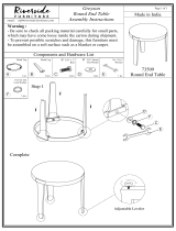
PARTS REQUIRED:
12 pcs - H1 Allen Head Bolt 2 pcs - P2 Right Leg
12 pcs - H2 Flat Washer 2 pcs - P3 Left Leg
1 pc - P1 Air Hockey Cabinet 4 pcs - P6 Leg Leveler
FIGURE 1
STEP 1:
Leave P1 Air Hockey Table Cabinet face down in
carton to assemble.
Install P2 Right Legs and P3 Left Legs onto P1 Air
Hockey Cabinet using H1 Allen Head Bolts and
H2 Flat Washers as shown in FIGURE 1.
Do not tighten H1 Bolts during this step.
Thread P6 Leg Levelers as shown in FIGURE 1.
P6
P2
P3
P3
P2
H2
H1
P1
PARTS REQUIRED:
16 pcs - H4 Phillips Round Head Screw
2 pcs - P4 End Leg Panel
2 pcs - P5 Side Leg Panel
STEP 2:
Install P4 End Leg Panels and P5 Side
Leg Panels using pilot holes with
H4 Phillips Round Head Screws as
shown in FIGURE 2.
Tighten, But do not strip out H4 Screws.
Tighten all H1 Bolts with T1 Allen Wrench
at this time from STEP 1.
H2
H1
H4
H4
P5
P5
P4
P4
THIS STEP REQUIRES TWO OR MORE ADULTS.
VERY CAREFULLY TURN THE TABLE OVER AND SET IT ON
ITS LEGS. BE CAREFUL, THE TABLE IS HEAVY.
IMPORTANT NOTE:
Graphics must be upside down
and face outside during assembly.
Graphics must be upside
down and face outside.
NOTE:
Pilot holes are located inside of
the P2 and P3 Legs.
P2
P3
P2
P3
FIGURE 2

©
2016 Escalade Sports
For Customer Service Call 1-888-996-2729
6
All Rights Reserved.
PARTS REQUIRED:
8 pcs - H3 Phillips Round Head Screw
2 pcs - P7 Goal Box with Sensors
STEP 3:
First, feed the sensor plug from each P7 Goal Box with Sensors through each end apron and underneath table support
frames as shown in FIGURE 3 and UNDERNEATH TABLE DIAGRAM. Guide the sensor wires following the path shown
with the arrows in FIGURE 3 and THE UNDERNEATH TABLE DIAGRAM from the goal box to the junction box
Connect P7 Goal Box with Sensors connectors to underneath C3 Junction Box as shown in FIGURE 3.
Secure P7 Goal Box with Sensors onto P1 Air Hockey Cabinet using pilot holes with H3 Phillips Round Head
Screws as shown in FIGURE 3. Tighten, But do not strip out H3 Screws.
P7
H3
P1
P7
FIGURE 3
C3
Junction Box
(underneath table)
C1
DC Motor
(underneath table)
C2B
BLUE LED Corner Post
C2R
RED LED Corner Post
C2R
RED LED
Corner Post
UNDERNEATH TABLE
C1 DC Motor
GOAL BOX
GOAL BOX
C3 Junction Box
IMPORTANT NOTE:
Be sure to route the goal box sensor
wires thru the support beam cutouts
for correct assembly.
IMPORTANT NOTE:
As you attach the P7 Goal Boxes,
make sure to very lightly pull any
excess wire thru the end apron that
may be blocking the electronic scoring
sensor eyes.
IMPORTANT NOTE:
the connectors that plug into the junction box
will only fit into their slots when turned correctly.
A flashlight may be helpful to achieve this
correct installation.
C2B
BLUE LED Corner Post

PARTS REQUIRED:
2 pcs - H4 Phillips Round Head Screw
1 pc - P8 Electronic Scorer
1 pc - A5 A/C Adapter
STEP 4:
First, feed the plug from P8 Electronic Scorer through side apron and connect to underneath C3 Junction Box as shown
in FIGURE 4 and UNDERNEATH TABLE DIAGRAM.
Secure P8 Electronic Scorer using Pre-drilled holes with H4 Phillips Round Head Screws as shown in FIGURE 4.
Tighten, But do not strip out H4 Screws.
Install 3 “AAA” size batteries into C3 Junction Box.
Connect A5 A/C Adapter onto C1 DC Motor (underneath table) as shown.
©
2016 Escalade Sports
For Customer Service Call 1-888-996-2729
7
All Rights Reserved.
UNDERNEATH TABLE
C1 DC Motor
GOAL BOX
GOAL BOX
ELECTRONIC
SCORER
H4
P8
C3
Junction Box
(underneath table)
C1
DC Motor
(underneath table)
A5
FIGURE 4
C3 Junction Box

©
2016 Escalade Sports
For Customer Service Call 1-888-996-2729
All Rights Reserved.
8
LED PUCK BATTERY CHANGE INSTRUCTION
STEP ONE:
Remove screws and back
cap from LED Puck using Small
Phillips Screwdriver (not provided).
STEP TWO:
Remove CR2016 Lithium
Battery 3V from LED Puck.
STEP THREE:
Insert new CR2016 Lithium Battery 3V
into LED Puck.
STEP FOUR:
Install back cap and secure screws with Phillps Screwdriver
(not provided).
Positive “+”
on bottom
side
LED STRIKER BATTERY CHARGE INSTRUCTION
NOTE:
Make sure the on/off
switch on the back
cap properly aligns
and fits into its slot in
the LED puck during
reassembly
IF BATTERY HOLDER BRACKET
MOVES, RE-INSTALL IT TO LED
PUCK AS SHOWN IN DIAGRAM.
USB Port
LED INDICATOR WILL LIGHT-UP DURING CHARGING AND
WILL TURN OFF WHEN ITS FULLY CHARGED.
Helpful Hint:
The LED puck battery will last approximately 7 hours of continuous play. The puck battery is not
rechargeable. Be sure to turn the switch to the “OFF” position when not in use to conserve your
battery life.
Helpful Hint:
The LED strikers each will require about 4 hours to fully charge up and will last approximately
7 hours of continuous play time. Be sure to turn the switch to the “OFF” position when not in use.

©
2016 Escalade Sports
For Customer Service Call 1-888-996-2729
All Rights Reserved.
9
Congratulations! You have now assembled your hockey table. Please note the Care and Use
instructions below to insure many years of trouble free use of your hockey table.
CARE AND USE OF YOUR HOCKEY TABLE
.2
rofdednetnisitcudorpsihT INDOOR use only.
.5
DO NOT sit, climb or lean on the table.
DO NOT drag the table when moving it. This will damage the legs.
DO NOT set drinks on the table.
It is suggested that this table be placed close to wall thus allowing the A/C Adapter
cord to NOT be a trip hazard. Always unplug A/C Adapter from wall when table is
not in use.
.6
.7
8.
For long life and best play from your air hockey table, apply spray furniture polish
to clean cloth and wipe down the playfield with air motor running to make the pucks
slide faster before first play and frequently thereafter.
3.
4.
DO NOT operate the motor if the A/C Adapter cord is damaged in any way.
.1
Use only a suitable 120v AC household outlet, and insure the cord is not a trip hazard.
Qty
Description
Part#
PRODUCT PARTS LIST 45-6060
Qty
Description
Part#
45-6060HLH1 6 mm x 28 mm Allen Head Bolt 12
45-6060HLH2 6.5 mm x 16 mm Flat Washer 12
45-6060HLH3 3.5 mm x 12 mm
Phillips Round Head Screw 8
45-6060HLH4 3.5 mm x 14 mm
Phillips Round Head Screw 18
45-6060HLA1R RED LED Striker 1
45-6060HLA1B BLUE LED Striker 1
45-6060HLA2 RED LED Puck 1
45-6060HLA3 Puck 2
45-6060HLA4 Felt Pad 2
45-6060HLA5 A/C Adapter 1
45-6060HLA6 USB Cable 1
45-6060HLP1 Air Hockey Cabinet (no motor) 1
45-6060HLP2 Right Leg 2
45-6060HLP3 Left Leg 2
45-6060HLP4 End Leg Panel 2
45-6060HLP5 Side Leg Panel 2
45-6060HLP6 Leg Leveler 4
45-6060HLP7 Goal Box with Sensors 2
45-6060HLP8 Electronic Scorer 1
45-6060HLC1 DC Motor 1
45-6060HLC2R RED LED Corner Post 2
45-6060HLC2B BLUE LED Corner Post 2
45-6060HLC3 Junction Box 1
45-6060HLK1 Hardware Kit 1
45-6060HLM1 Owner’s Manual 1

©
2016 Escalade Sports
For Customer Service Call 1-888-996-2729
10
All Rights Reserved.
This consumer warranty extends to the original consumer purchase of any ESCALADESPORTS
Product (hereinafter referred as the "Product").
WARRANTY DURATION: This Product is warranted to the original consumer purchase of a pe-
riod of 90 days from the original purchase.
WARRANTY COVERAGE: ESCALADE SPORTS warrants to the original Consumer Purchaser
that any Product of its manufacture is free from defects in material and workmanship when used
for the intended purpose under normal use and conditions. THIS WARRANTY IS VOID IF THE
PRODUCT HAS BEEN DAMAGED BY ACCIDENT, UNREASONABLE USE, NEGLIGENCE,
IMPROPER SERVICE, FAILURE TO FOLLOW INSTRUCTIONS PROVIDED WITH THE PROD-
UCT OR OTHER CAUSES NOT ARISING OUT OF DEFECTS IN MATERIAL AND WORKMAN-
SHIP.
WARRANTY PERFORMANCE: During the above 90 day warranty period, ESCALADESPORTS
shall repair or replace with a comparable model, and Product, or component thereof, which may
prove defective under normal use and proper care, and which our examination shall disclose to
our satisfaction to be thus defective, please contact our Warranty Dept.
1-888-996-2729 / Warranty Dept.
Or Write us at:
Escalade® Sports, Inc. - P.O. Box 889, Evansville, IN 47706
Attn: Warranty Dept.
Or E-mail us at:
Other than shipping requirements no charge will be made for such repair or replacement of in-
warranty Products. ESCALADE SPORTS strongly recommends that the Product is insured for
value prior to mailing.
WARRANTY DISCLAIMERS: ANY IMPLIED WARRANTIES ARISING OUT OF
THIS SALE, INCLUDING BUT NOT LIMITED TO THE IMPLIED WARRANTIES OF
MERCHANTABILITY AND FITNESS FOR A PARTICULAR PURPOSE, ARE LIM-
ITED IN DURATION TO THE ABOVE 90 DAY PERIOD. ESCALADE SPORTS
SHALL NOT BE LIABLE FOR LOSS OF USE OF THE PRODUCT OR OTHER
CONSEQUENTIAL OR INCIDENTAL COSTS, EXPENSES OR DAMAGES IN-
CURRED BY THE CONSUMER OF ANY OTHER USE.
Some states do not allow the exclusion or limitation of implied warranties or consequential or
incidental damages, so the above limitations or exclusions may not apply to you.
LEGAL REMEDIES: This warranty gives you specific legal rights and you may also have other
rights which may vary from state to state.
90 DAY LIMITED WARRANTY
/