subzero.com | 9
Installation
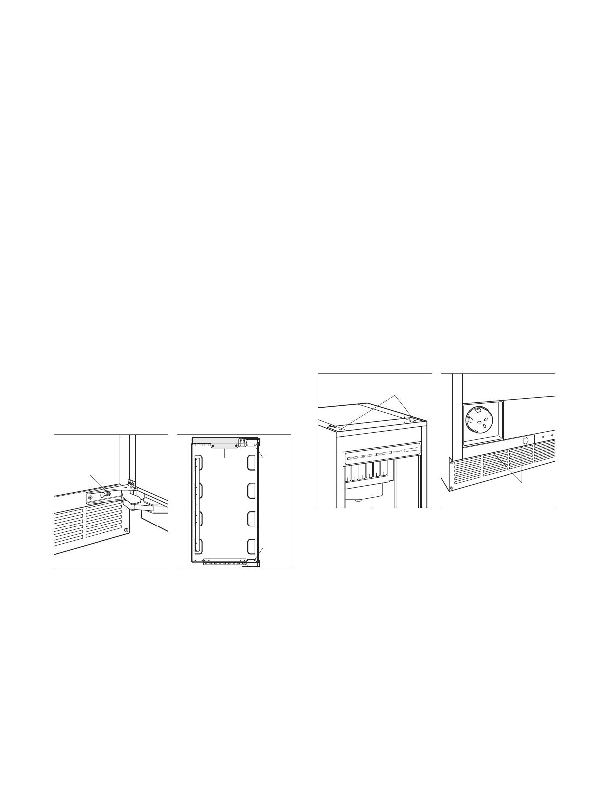
REVERSE DOOR SWING
The door hinges are designed to be placed on either the
right or left side of the ice maker. The unit is shipped with
the door hinged on the right. Moving the hinges to the left
using the pre-drilled holes allows for a left-hand door swing.
To Reverse the Door Swing:
1 Detach the hinges from the ice maker by removing two
screws per hinge, then remove the door. Remove the
shim located between the cabinet and bottom hinge, this
shim will transfer to the left side bottom hinge.
2 Detach the hinges from the door by removing two
screws per hinge.
3 Detach the right-hand upper trim (shaded area) from the
door by removing the two screws. Refer to the illustra-
tion below. Replace it with the left-hand upper trim.
4 Transfer the hinges to the left side of the door and
reinstall. The upper hinge will now be in the lower hinge
position and the lower hinge in the upper hinge position.
5 Remove the top cover of the ice maker by removing the
two screws at the top rear of the unit.
6 Remove the four screws from the front top rail, then pivot
the top rail end for end to expose the two left-hand top
hinge mounting holes and reinstall. Refer to the illustra-
tion below.
7 Remove the two screws from the lower edge of the
bottom trim plate and slide it to the right to cover
the right hinge mounting holes. Refer to the illustra-
tion below. The left hinge mounting holes will now be
exposed.
8 Reinstall the shim removed in step 1, between the
cabinet and the left side bottom hinge. Reinstall the door
by mounting the hinges using the left hinge mounting
holes. Verify operation of the door.
INSTALLATION
HINGE
SCREWS
UPPER
TRIM (RH)
HINGE
HINGE
Remove door
Detach hinges and trim
TOP RAIL
SCREWS
TRIM PLATE
SCREWS
Front top rail
Bottom trim plate


