Moxa UC-8100 Series Quick setup guide

Type
Quick setup guide

Moxa UC-8100 Series is a computing platform designed for embedded data acquisition applications. It features one or two RS-232/422/485 serial ports and dual 10/100 Mbps Ethernet LAN ports, enabling efficient adaptation to complex communication solutions. The Mini PCIe socket supports cellular modules for wireless communication, providing versatile connectivity options.

Moxa UC-8100 Series is a computing platform designed for embedded data acquisition applications. It features one or two RS-232/422/485 serial ports and dual 10/100 Mbps Ethernet LAN ports, enabling efficient adaptation to complex communication solutions. The Mini PCIe socket supports cellular modules for wireless communication, providing versatile connectivity options.

1 2 3
P/N: 1802081000012
*1802081000012*
UC-8100 Series
Quick Installation Guide
Version 3.0, January 2019
Overview
The UC-8100 computing platform is designed for embedded data
acquisition applications. The computer comes with one or two
RS-232/422/485 serial ports and dual 10/100 Mbps Ethernet LAN
ports, as well as a Mini PCIe socket to support cellular modules.
These versatile communication capabilities let users efficiently
adapt the UC-8100 to a variety of complex communication
solutions.
Package Checklist
Before installing the UC-8100, verify that the package contains the
following items:
UC-8100 embedded computer
Console cable
Power jack
3-pin terminal block for power (preinstalled on UC-8100)
5-pin terminal block for UART x 2 (preinstalled on UC-8100)
NOTE: Notify your sales representative if any of the above items
are missing or damaged.
UC-8100 Panel Layout
The following figures show the panel layouts of the UC-8100.
Top and Bottom View
Top
Bottom
Front View
LED Indicators
LED Name
Color
Function
USB
Green
USB device is connected
and working normally
Off USB device is not
connected.
SD
Green
SD Card inserted and
working normally
SD card is not detected
Power Green Power is on and the computer is
working normally.
Off
Power is off.
LAN1/2
(On RJ45
connector
)
Green
100 Mbps Ethernet link
Data transmitting
Yellow
10 Mbps Ethernet link
Data transmitting
Off
Ethernet is not connected
Wireless
Signal
Strength
Green
Yellow
Red
Number of glowing LEDs indicates
signal strength
3 (Green + Yellow + Red): Excellent
2 (Yellow + Red): Good
1 (Red): Poor
Off
Wireless module is not detected
Diagnosis
Program-
mable
Green
Yellow
Red
Refer Chapter 3 in the Hardware
Manual for details.
These 3 LEDs are programmable;
refer
to Chapter 5 in the Hardware Manual
for details.
Installing the UC-8100
There are two sliders on the back of the unit for DIN rail and wall
mounting.
Mounting on a DIN Rail
Pull out the bottom slider, latch the unit onto the DIN rail, and push
the slider back in.
Mounting on a Wall
Pull out both the top and bottom
sliders and align the screws
accordingly.
Another method for wall mounting installation is to use the
optional wall mounting kit. Attach two mounting brackets on the
side panel of the computer, and fasten with screws. Install the
computer on a wall or cabinet by fastening two screws for each
bracket.
Connector Description
Power Connector
Connect the “terminal block to power jack converter” (in the
package) to the UC-8100s DC terminal block (located on the top
panel), and then connect the power adapter. It takes about 30
seconds for the system to boot up. Once the system is ready, the
Ready LED will light up.
4 5 6
www.moxa.com/support
The Americas:
+1-714-528-6777 (toll-free: 1-888-669-2872)
Europe:
+49-89-3 70 03 99-0
Asia-Pacific:
+886-2-8919-1230
China:
+86-21-5258-9955 (toll-free: 800-820-5036)
India:
+91-80-4172-9088
2019 Moxa Inc. All rights reserved.
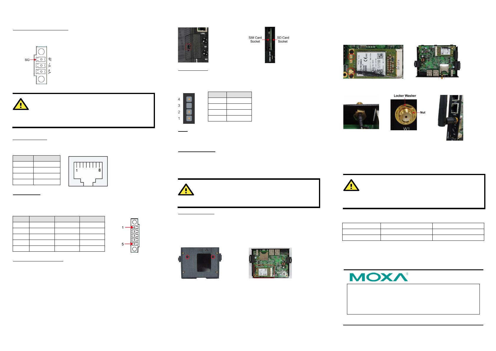
Grounding the UC-8100
Grounding and wire routing help limit the effects of noise due to
electromagnetic interference (EMI).
SG:
The Shielded Ground (sometimes
called Protected Ground) contact is
the
top contact of the 3-pin power
terminal block connector when
viewed from the angle shown here.
Connect the SG wire to an
appropriate grounded metal surface.
ATTENTION
The product is intended to be supplied by an UL Listed
power adapter whose output meets SELV/LPS, and is rated
12-24 VDC, minimum 0.5 A, Tma = 85°C (minimum).
Ethernet Ports
The two 10/100 Mbps Ethernet ports (LAN 1 and LAN 2) use RJ45
connectors.
Pin
Signal
1
ETx+
2
ETx-
3
ERx+
6
ERx-
Serial Ports
The two serial ports (P1 and P2) use terminal connectors. Each
port can be configured by software for RS-232, RS-422, or RS-485.
The pin assignments for the ports are shown in the following table:
Pin
RS-232
RS-422
1
TXD
TXD+
2
RXD
TXD-
3
RTS
RXD+
4
CTS
RXD-
5
GND
GND
SD/SIM Card Sockets
The UC-8100 comes with an SD socket for storage expansion, and
a SIM card socket for cellular communication. The SD card/SIM
card sockets are located at the lower part on the front panel. To
install them, remove the screw and the protection cover to access
the sockets, and then plug the SD card or the SIM card into the
sockets directly. You will hear clickwhen finished. Remember to
push in on the SD card or SIM card first if you want to remove
them.
Console Port
The console port is an RS-232 port that can be connected with a
4-pin pin header cable. You may use this port for debugging or
firmware upgrade.
Pin
Signal
1
TxD
2
RxD
3
NC
4
GND
USB
The USB 2.0 port is located at the lower part of the front panel, and
supports a USB storage device driver.
Real Time Clock
The UC-8100’s real time clock is powered by a non-chargeable
battery. We strongly recommend that you do not replace the
battery without help from a qualified Moxa support engineer. If you
need to change the battery, contact the Moxa RMA service team.
ATTENTION
There is
a risk
of explosion if the battery is replaced by an
incorrect type of battery.
Cellular Module
The UC-8100 comes with a PCIe socket inside for wireless
communication. Follow these steps:
1. Remove the screws on the side panel, and take off the cover.
2. Find the location of the PCIe socket. Insert the cellular module
into the socket. Fasten the socket with screws.
3. Next you need to install the antenna cable. There are two
antenna connectors on the cellular module. Connect the cable
onto either connector.
4. Install the other end of the cable onto the connector on the
front panel of the UC-8100. Remove the black plastic cover
first.
5. Install the connector, place the locker washer first, and then
insert the nut. Connect the antenna onto the connector.
Connecting the UC-8100 to a PC
A. Through the serial console port with the following settings:
Baudrate=115200 bps, Parity=None, Data bits=8, Stop
bits =1, Flow Control=None
ATTENTION
Remember to choose the “VT100” terminal type. Use the
CBL
-RJ45F9-150 cable included in the package
to connect a
PC to the UC-8100’s serial console port.
B. By SSH over the network. Refer to the following IP addresses
and login information.
Default IP Address
Netmask
LAN 1
192.168.3.127
255.255.255.0
LAN 2
192.168.4.127
255.255.255.0
Login: moxa
Password: moxa
  • Page 1 1
  • Page 2 2

Moxa UC-8100 Series Quick setup guide

Type
Quick setup guide

Moxa UC-8100 Series is a computing platform designed for embedded data acquisition applications. It features one or two RS-232/422/485 serial ports and dual 10/100 Mbps Ethernet LAN ports, enabling efficient adaptation to complex communication solutions. The Mini PCIe socket supports cellular modules for wireless communication, providing versatile connectivity options.

Ask a question and I''ll find the answer in the document

Finding information in a document is now easier with AI