Page is loading ...

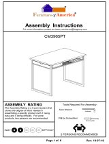
FPI FIREPLACE PRODUCTS INTERNATIONAL LTD. 6988 Venture St., Delta, BC Canada, V4G 1H4919-546c
MODEL: H300
Freestanding Woodstove
07.24.18
Installer: Please complete the details on the back cover
and leave this manual with the homeowner.
Homeowner: Please keep these instructions for future reference.
Owners &
Installation Manual
Tested by:
www.hampton-re.com
French Manual: http://ow.ly/ZvnBd
Manuel en Français: http://ow.ly/ZvnBd

2 | Hampton® H300 Cast Freestanding Woodstove
|
2
Thank-you for purchasing a HAMPTON PRODUCT.
The pride of workmanship that goes into each of our products will give you years of trouble-free enjoyment. Should you have any questions about your product
that are not covered in this manual, please contact the HAMPTON DEALER in your area. Keep those HAMPTON FIRES burning.
“This wood heater has a manufacturer set minimum low burn rate that must not be altered. It is against federal regulations to alter this setting or otherwise
operate this wood heater in a manner inconsistent with operating instructions in this manual." Failure to follow the manual details can lead to smoke and CO
emissions spilling into the home. It is recommended to have monitors in areas that are expected to generate CO such as heater fuelling areas.
“U.S. ENVIRONMENTAL PROTECTION AGENCY Certied to comply with 2015 particulate emission standards using crib wood". Not approved for sale after
May 15, 2020.”
Model Regency H300 – 4.2 g /hr.
SAFETY NOTE: If this woodstove is not properly installed, a house re may result. For your safety, follow the installation instructions, contact local building,
re ocials, or authority having jurisdiction about restrictions and installation inspection requirements in your area.
The following statements are required by the Environmental Protection Agency:
“This manual describes the installation and operation of the Regency H300 wood heater. This heater meets the 2015 U.S. Environmental Protection Agency’s
crib wood emission limits for wood heaters. Under specic test conditions this heater has been shown to deliver heat at rates ranging from 10,600 BTU/hr. to
28,500 BTU/hr.” This unit has been tested using 5G series and generates the best eciency when operated using well-seasoned wood and installed in the
main living areas where the majority of the chimney is within the building envelope and fully lined.”
"It is against federal regulation to operate this wood heater in a manner inconsistent with operating instructions in this manual, or if any parts are removed. “
It is against federal regulation to operate this wood heater in a manner inconsistent with operating instructions in this manual.
CAUTION: BURN UNTREATED WOOD ONLY. OTHER MATERIALS SUCH AS WOOD PRESERVATIVES, METAL FOILS, COAL,
PLASTIC, GARBAGE, SULPHUR OR OIL MAY DAMAGE THE HEATER
"This heater is designed to burn natural wood only. Higher eciencies and lower emissions generally result when burning air dried seasoned hardwoods, as
compared to softwoods or to green or freshly cut hardwoods."
DO NOT BURN:
• Treated wood • Lawn clippings or yard waste • Manure or animal remains
• Coal • Materials containing rubber including tires • Saltwater driftwood or other previously salt water
saturated materials
• Garbage • Materials containing plastic • Unseasoned wood
• Cardboard • Waste petroleum products , paints or paint thinners or asphalt products • Paper products, cardboard, plywood or particle
board. The prohibition against burning these
materials does not prohibit the use of fire starters
made from paper, cardboard, saw dust, wax and
similar substances for the purpose of starting a
fire in a wood heater
• Solvents • Materials containing asbestos
• Colored Paper • Construction or demolition debris
• Trash • Railroad ties
Burning these materials may result in release of toxic fumes or render the heater ineective and cause smoke.
The authority having jurisdiction (such as Municipal Building Department, Fire Department, Fire Prevention Bureau, etc.) should be consulted before installa-
tion to determine the need to obtain a permit.
This unit must be connected to either a listed factory built chimney suitable for use with solid fuels and conforming to ULC629 in Canada or UL-103HT in the
United States of America or code approved masonry chimney with ue liner.
H300 is tested and certified to ULC-S627 and UL1482.
SAVE THESE INSTRUCTIONS

Hampton® H300 Cast Freestanding Woodstove | 3
3
|
table of contents
SAFETY LABEL
Copy of Safety Label for H300 .......................................4
INSTALLATION
Unit Dimensions with Standard Legs .............................5
Unit Dimensions with Optional Short Legs ....................6
Pre-installation Assembly ..............................................7
Residential Installation ...................................................8
Modular Installation Options ..........................................8
Minimum Clearance To Combustible Materials ..............9
Minimum Alcove Clearance To
Combustible Materials .................................................10
Additional Clearances For Backwall Exit .....................10
Floor Protection ...........................................................11
How To Determine If Alternate
Floor Protection Materials Are Acceptable ..................12
Step-by-Step Chimney and Connector Installation ......12
Factory Built Chimney..................................................12
Masonry Chimney........................................................13
Masonry Fireplace .......................................................13
Combustible Wall Chimney Connector
Pass-throughs .............................................................14
Recommended Heights For Woodstove Flue ..............15
Mobile Home Installation .............................................16
Listed Components For Mobile Home Installation .......17
Brick Installation ..........................................................18
Door Removal ..............................................................18
Glass Installation .........................................................18
Optional Short Leg Installation ....................................19
Optional Blower / Fan Installation ................................21
Side Shelf Installation ..................................................22
OPERATING INSTRUCTIONS
Seasoned wood ...........................................................23
Operating Instructions .................................................24
Fan Operation ..............................................................24
First Fire ......................................................................24
Safety Guidelines and Warnings .................................25
Draft Control ................................................................25
Ash Disposal ................................................................26
Creosote ......................................................................27
Glass Maintenance ......................................................27
MAINTENANCE
Maintenance ................................................................27
Wood Storage ..............................................................27
Front Door Gasket .......................................................28
Side Door Gasket ........................................................28
Handle Replacement ...................................................28
Latch Adjustment Method ............................................28
Side Door Adjustment ..................................................28
Top Baffle Replacement ..............................................29
Annual Maintenance ....................................................30
PARTS LIST
H300 Main Assembly ...................................................31
H300 Door Assembly ...................................................33
H300 Firebrick .............................................................34
WARRANTY
Warranty ......................................................................35
ALL PICTURES / DIAGRAMS SHOWN THROUGHOUT THIS MANUAL ARE FOR ILLUSTRATION PURPOSES ONLY.
ACTUAL PRODUCT MAY VARY DUE TO PRODUCT ENHANCEMENTS.

4 | Hampton® H300 Cast Freestanding Woodstove
|
4
safety decal
This is a copy of the label that accompanies
each Hampton H300 Freestanding Woodstove.
We have printed a copy of the contents here
for your review.
NOTE: Hampton units are constantly being
improved. Check the label on the unit and if
there is a dierence, the label on the unit is the
correct one.
COPY OF SAFETY LABEL FOR H300
Part #: 918-216d
Size: 7.489" H x 10.47" W (File at 100%)
Color: Black on grey except what is indicated is printed red on grey.
Jan. 31/08: added short leg option.
Mar. 1/10: updated logo
Jan. 21/13: Updated date of manufacture
Jan. 30/14: Rev. C - Added French copy
May 06/15: Updated yrs. of manufacture/removed 1990 EPA info
Apr 29/16: Rev. D - Updated yrs. of manufacture 2017-2021
DO NOT REMOVE THIS LABEL
NE PAS RETIRER CETTE ÉTIQUETTE
254
MADE IN CANADA / FABRIQUÉ AU CANADA
CAUTION
LISTED SPACE HEATER, SOLID FUEL TYPE, ALSO
SUITABLE FOR MOBILE HOME INSTALLATION
APPAREIL DE CHAUFFAGE AMBIANT HOMOLOGUÉ
À COMBUSTIBLE SOLIDE, CONVENANT AUSSI
POUR INSTALLATION DANS UNE MAISON MOBILE
MODEL: HAMPTON CAST FREESTANDING WOOD STOVE - H300
MODÈLE : POÊLE À BOIS AUTOPORTANT EN FONTE HAMPTON - H300
TESTED TO: UL-1482, ULC-S627-00 REPORT NO: 219-S-04-2
MINIMUM ALCOVE CEILING HEIGHT: 1.5 M / 5 FT MAXIMUM ALCOVE DEPTH 1220 MM / 48 IN.
MINIMUM CLEARANCES FOR HORIZONTAL CONNECTOR TO CEILING: 457 MM / 18"
THE SPACE BENEATH THE HEATER MUST NOT BE OBSTRUCTED. OPERATE ONLY WITH FIREBRICKS IN PLACE.
FOR USE WITH SOLID WOOD FUEL ONLY. USE OF OTHER FUELS MAY DAMAGE HEATER AND CREATE A HAZARDOUS CONDITION.
DO NOT OBSTRUCT COMBUSTION AIR OPENINGS. OPERATE ONLY WITH FIREBRICKS IN PLACE. OPERATE ONLY WITH DOOR
CLOSED - OPEN FEED DOOR TO FEED FIRE ONLY. DO NOT USE GRATE OR ELEVATE FIRE. BUILD WOOD FIRE DIRECTLY ON
HEARTH. DO NOT OVERFIRE - IF HEATER OR CHIMNEY CONNECTOR GLOWS YOU ARE OVERFIRING. INSPECT AND CLEAN
CHIMNEY AND CONNECTOR FREQUENTLY. UNDER CERTAIN CONDITIONS OF USE CREOSOTE BUILDUP MAY OCCUR RAPIDLY.
KEEP FURNISHINGS AND OTHER COMBUSTIBLE MATERIAL AWAY FROM HEATER. REPLACE GLASS ONLY WITH NEOCERAM
GLASS. COMBUSTIBLE FLOOR MUST BE PROTECTED BY NON-COMBUSTIBLE MATERIAL EXTENDING BENEATH THE HEATER
AND TO THE FRONT AND SIDES AS INDICATED OR TO THE NEAREST PERMITTED COMBUSTIBLE MATERIAL.
OPTIONAL COMPONENT: FAN (846-515), ELECTRICAL RATING: VOLTS 115, 60 HZ, 2 AMPS, SHORT LEGS (200-931, 200-935)
DANGER: RISK OF ELECTRIC SHOCK. DISCONNECT POWER BEFORE SERVICING UNIT. DO NOT ROUTE POWER CORD UNDER
OR IN FRONT OF APPLIANCE.
COMPONENTS REQUIRED FOR MOBILE HOME INSTALLATION: OUTSIDE AIR KIT AND ONE OF THE FOLLOWING DOUBLE WALL
CONNECTOR
IN CANADA: LISTED SECURITY MODEL DP, OR OLIVER MACLEOD PRO-VENT PV DOUBLE WALLED CONNECTOR WITH LISTED
CHIMNEY SYSTEM: SECURITY MODEL S2100, ICC EXCEL 2100.
IN USA: LISTED DOUBLE WALL CONNECTORS SECURITY MODEL DP, SELKIRK MODEL DS, OLIVER MACLEOD PRO VENT PV,
SIMPSON DURA VENT MODEL DVL, GSW SUPER PIPE 6, METAL-FAB DOUBLE WALL. CONNECTED TO ONE OF THE FOLLOWING
COMPATIBLE CHIMNEY SYSTEMS SECURITY MODEL S2100 OR MODEL ASHT, SELKIRK MODEL SSII, OLIVER MACLEOD PRO JET
3103, SIMPSON DURA PLUS, GSW MODEL SC OR METAL-FAB TEMP/GUARD, AMERI-TECHS, ICC EXCEL 2100 . USE CHIMNEY
COMPONENTS AS SPECIFIED IN INSTALLATION INSTRUCTIONS.
HAUTEUR MINIMALE DU PLAFOND DE L’ALCÔVE : 1,5 M / 5 PI. PROFONDEUR MAX. DE L’ALCÔVE : 1220 MM / 48 PO.
DÉGAGEMENT MINIMAL DU PLAFOND POUR UN CONNECTEUR HORIZONTAL : 457 MM / 18 PO.
L’ESPACE AU-DESSOUS DU POÊLE NE DOIT PAS ÊTRE OBSTRUÉ. UTILISER SEULEMENT AVEC LES BRIQUES RÉFRACTAIRES
EN PLACE.
POUR UTILISATION AVEC BOIS SOLIDE SEULEMENT. L’UTILISATION D’AUTRES COMBUSTIBLES PEUT ENDOMMAGER LE
POÊLE
ET S'AVÉRER DANGEREUSE. NE PAS OBSTRUER LES OUVERTURES D’AIR DE COMBUSTION. UTILISER SEULEMENT
AVEC LA PORTE FERMÉE – OUVRIR LA PORTE DE CHARGEMENT SEULEMENT POUR ALIMENTER LE FEU. NE PAS UTILISER
DE GRILLE À BÛCHES NI SURÉLEVER LE FEU. MONTER LE FEU DE BOIS DIRECTEMENT SUR L’ÂTRE. NE PAS SURCHAUFFER
– SI LE POÊLE OU LE CONNECTEUR DE CHEMINÉE SE MET À ROUGIR,
C'EST LE SIGNE D'UNE SURCHAUFFE. INSPECTER ET
NETTOYER FRÉQUEMMENT LA CHEMINÉE ET LE CONNECTEUR. DANS CERTAINES CONDITIONS D’UTILISATION, UN DÉPÔT
DE CRÉOSOTE PEUT SE FORMER RAPIDEMENT. TENIR LES MEUBLES ET AUTRES MATÉRIAUX COMBUSTIBLES ÉLOIGNÉS
DU POÊLE. REMPLACER LA VITRE SEULEMENT PAR DU VERRE EN NEOCERAM. LE PLANCHER COMBUSTIBLE DOIT ÊTRE
PROTÉGÉ PAR DES MATÉRIAUX NON COMBUSTIBLES DÉPASSANT DU DESSOUS, DU DEVANT ET DES CÔTÉS DU POÊLE, TEL
QU’INDIQUÉ, OU JUSQU’AU MATÉRIAU COMBUSTIBLE LE PLUS PROCHE PERMIS.
COMPOSANTS EN OPTION : VENTILATEUR (846-515), ALIMENTATION ÉLECTRIQUE : 115 VOLTS, 60 HZ, 2 AMP.
DANGER : RISQUE D’ÉLECTROCUTION. DÉCONNECTER L’ALIMENTATION ÉLECTRIQUE AVANT DE FAIRE L’ENTRETIEN DU
POÊLE. NE PAS INSTALLER LE CORDON ÉLECTRIQUE SOUS OU DEVANT L’ APPAREIL.
COMPOSANTS EXIGÉS POUR L'INSTALLATION DANS UNE MAISON MOBILE : KIT DE PRISE D’AIR EXTÉRIEUR ET UN DES
CONNECTEURS DE CHEMINÉE À DOUBLE PAROI SUIVANTS :
AU CANADA : CONNECTEURS DE CHEMINÉE HOMOLOGUÉS À DOUBLE PAROI : SECURITY MODÈLE DP, OU OLIVER MA-
CLEOD PRO-VENT PV, AVEC SYSTÈME DE CHEMINÉE HOMOLOGUÉ : SECURITY MODÈLE S2100, ICC EXCEL 2100.
AUX ÉTATS-UNIS : CONNECTEURS DE CHEMINÉE HOMOLOGUÉS À DOUBLE PAROI : SECURITY MODÈLE DP, SELKIRK MODEL
DS, OLIVER MACLEOD PRO VENT PV, SIMPSON DURA VENT MODÈLE DVL, GSW SUPER PIPE 6, METAL-FAB À DOUBLE PAROI.
CONNECTÉ À L’UN DES SYSTÈMES DE CHEMINÉE COMPATIBLES SUIVANTS : SECURITY MODÈLE S2100 OU MODÈLE ASHT,
SELKIRK MODÈLE SSII, OLIVER MACLEOD PRO JET 3103, SIMPSON DURA PLUS, GSW MODÈLE SC OU METAL-FAB TEMP/
GUARD, AMERI-TECHS, ICC EXCEL 2100. UTILISER LES COMPOSANTS DE CHEMINÉE SPÉCIFIÉS DANS LES INSTRUCTIONS
D’INSTALLATION.
FLOOR
PROTECTION*/ PROTEC-
TION DE PLANCHER*
INSTALL AND USE ONLY IN ACCORDANCE WITH THE MANUFACTURER'S INSTALLATION AND OPERATING INSTRUCTIONS.
CONTACT LOCAL BUILDING OR FIRE OFFICIALS ABOUT RESTRICTIONS AND INSTALLATION INSPECTION IN YOUR AREA.
USE 150 MM (6 IN.) DIAMETER MINIMUM 24 MSG BLACK OR 26 MSG BLUED STEEL CONNECTOR WITH LISTED UL103 HT
FACTORY-BUILT CHIMNEY SUITABLE FOR USE WITH SOLID FUELS OR MASONRY CHIMNEY.
SEE LOCAL BUILDING CODE AND MANUFACTURER'S INSTRUCTIONS FOR PRECAUTIONS REQUIRED FOR PASSING
A CHIMNEY THROUGH A COMBUSTIBLE WALL OR CEILING. DO NOT PASS CHIMNEY CONNECTOR THROUGH
COMBUSTIBLE WALL OR CEILING. DO NOT CONNECT THIS UNIT TO A CHIMNEY FLUE SERVING ANOTHER APPLIANCE.
INSTALLER ET UTILISER SEULEMENT SELON LES CONSIGNES D’INSTALLATION ET D’UTILISATION DU FABRICANT.
CONTACTER LES RESPONSABLES DU BÂTIMENT OU DU SERVICE-INCENDIE DE VOTRE RÉGION POUR CONNAÎTRE LES
RESTRICTIONS ET EXIGENCES D’INSPECTION DANS VOTRE RÉGION. UTILISER UN CONNECTEUR D’UN DIAMÈTRE MINIMAL
DE 150 MM (6 PO) 24 MSG EN ACIER NOIR OU 26 MSG EN ACIER BRONZÉ AVEC CHEMINÉE PRÉFABRIQUÉE HOMOLOGUÉE
UL103 HT CONÇUE POUR UTILISATION AVEC COMBUSTIBLES SOLIDES OU UNE CHEMINÉE DE MAÇONNERIE.
VOIR LE CODE DU BÂTIMENT LOCAL ET LES INSTRUCTIONS DU FABRICANT CONCERNANT LES PRÉCAUTIONS EXIGÉES
POUR INSTALLER UNE CHEMINÉE TRAVERSANT UN MUR OU PLAFOND EN MATÉRIAUX COMBUSTIBLES. NE PAS FAIRE
TRAVERSER LE CONNECTEUR DE CHEMINÉE DANS UN MUR OU PLAFOND EN MATÉRIAUX COMBUSTIBLES. NE PAS
RACCORDER CE POÊLE À BOIS À UN CONDUIT DE CHEMINÉE DESSERVANT UN AUTRE APPAREIL.
MANUFACTURED BY / FABRIQUÉ PAR :
FPI FIREPLACE PRODUCTS INTERNATIONAL LTD.
6988 VENTURE ST.
DELTA, BC V4G 1H4
MINIMUM CLEARANCES TO
COMBUSTIBLE MATERIALS
RESIDENTIAL INSTALLATION USING
SINGLE WALL CONNECTOR
SIDEWALL A 431 mm / 17 in D 762 mm / 30 in
BACKWALL B 381 mm / 15 in E 381 mm / 15 in
CORNER C 330 mm / 13 in F 483 mm / 19 in
INSTALLATION USING LISTED DOUBLE WALL
CONNECTOR - ALCOVE
INSTALLATION USING LISTED DOUBLE WALL
CONNECTOR - MOBILE HOME
SIDEWALL A 381 mm / 15 in D 711 mm / 28 in
BACKWALL B 254 mm / 10 in E 254 mm / 10 in
CORNER C 228 mm / 9 in F 381 mm / 15 in
SIDEWALL A 381 mm / 15 in D 711 mm / 28 in
BACKWALL B 254 mm / 10 in E 254 mm / 10 in
CORNER C 228 mm / 9 in F 381 mm / 15 in
INSTALLATION USING LISTED DOUBLE WALL
CONNECTOR - RESIDENTIAL CLOSE CLEARANCE
MEASURE FLUE
FROM HEATER CENTER-LINE
SIDEWALL G 381 mm / 15 in I 711 mm / 28 in
BACKWALL H 330 mm / 13 in J 330 mm / 13 in
JAN FEB MAR AP R MAY JUN JUL AUG SEPT OCT NOV DEC
DA
TE OF MANUF
ACTURE/DATE FABRICATION
20192018
2017
20212020
254
* In Canada, fl oor protection must extend 18"
(457mm) to the front and 8" (200mm) to each
side and back of the stove.
K 457 mm / 18 in
L 150 mm / 6 in
M 150 mm / 6 in
IF SIDE LOAD DOOR IS USED:
Floor protection must extend 18" (457mm) from the side of the
unit to the wall.
Floor protection must be a minimum of 3/8" thick with a mini-
mum k factor of 0.84.
Minimum clearance with side load door in use is 18" (457mm)
to side wall or refer to dimension (A) if side load door is not
used.
SI LA PORTE DE CHARGEMENT LATÉRALE EST UTILISÉE :
Une protection de plancher doit dépasser de 18 po (457 mm) du côté
de l'appareil au mur.
Une protection de plancher doit avoir une épaisseur d'au moins 3/8 po
avec un facteur de 0,84k minimum.
Si la porte de chargement latérale est utilisée, le dégagement minimum
est de 18 po (457 mm) à la paroi latérale ou se reporter à la cote (A) si
la porte de chargement latérale n'est pas utilisée.
HOT WHILE IN OPERATION DO NOT TOUCH. KEEP CHILDREN,
CLOTHING AND FURNITURE AWAY. CONTACT MAY CAUSE
SKIN BURNS. READ NAMEPLATE AND INSTRUCTIONS.
ATTENTION
SURFACES CHAUDES DURANT LE FONCTIONNEMENT.
NE PAS TOUCHER. TENIR LES ENFANTS, LES VÊTEMENTS
ET LES MEUBLES ÉLOIGNÉS DE L'APPAREIL.
TOUT CONTACT PEUT CAUSER DES BRÛLURES. LIRE LA
PLAQUE SIGNALÉTIQUE ET LES INSTRUCTIONS.
DÉGAGEMENTS MINIMAUX DES
MATÉRIAUX COMBUSTIBLES
INSTALLATION RÉSIDENTIELLE UTILISANT
UN CONNECTEUR À SIMPLE PAROI
MUR LATÉRAL
MUR ARRIÈRE
COIN
MUR LATÉRAL
MUR ARRIÈRE
COIN
MUR LATÉRAL
MUR ARRIÈRE
COIN
MUR LATÉRAL
MUR ARRIÈRE
A 431mm/17po
B 381mm/15po
C 330mm/13po
A 381mm/15po
B 254mm/10po
C 228mm/9po
A 381mm/15po
B 254mm/10po
C 228mm/9po
G 381mm/15po
H 330mm/13po
D 762mm/30po
E 381mm/15po
F 483mm/19po
D 711mm/28po
E 254mm/10po
F 381mm/15po
D 711mm/28po
E 254mm/10po
F 381mm/15po
I 711mm/28po
J 330mm/13po
INSTALLATION UTILISANT UN CONNECTEUR
HOMOLOGUÉ À DOUBLE PAROI - ALCÔVE
INSTALLATION UTILISANT UN CONNECTEUR
HOMOLOGUÉ À DOUBLE PAROI - MAISON MOBILE
INSTALLATION UTILISANT UN CONNECTEUR HOMOLOGUÉ
À DOUBLE PAROI - RÉSIDENTIELLE (DÉGAGEMENT
RÉDUIT)
MESURES
DU CENTRE DU
À PARTIR DU POÊLE
CONDUIT DE CHEMINÉE
* Au Canada, la protection de plancher doit dépasser de
18 po (457 mm) à l’avant et de 8 po (203 mm) de chaque
côté du poêle et derrière le poêle.
918-216d

Hampton® H300 Cast Freestanding Woodstove | 5
5
|
dimensions
UNIT DIMENSIONS WITH STANDARD LEGS

6 | Hampton® H300 Cast Freestanding Woodstove
|
6
dimensions
UNIT DIMENSIONS WITH OPTIONAL SHORT LEGS
22-1/8” (561mm)
24-3/8” (620mm)
27-5/8” (700mm)
23-1/4” (592mm)
24-3/4” (628mm)
17-3/8” (441mm)
2”
(52mm)
25-5/8” (650mm)
23” (583mm)
18-3/8” (468mm)
6-1/4”
(159mm)
26-7/8” (683mm)
16-1/2” (419mm)
24” (610mm)

Hampton® H300 Cast Freestanding Woodstove | 7
7
|
installation
PRE-INSTALLATION
ASSEMBLY
After removing the stove from its packing, open
the front door and remove the contents from the
rebox, leaving the bricks in place.
Side Load
Rotating Elbow
This stove can be connected to either a top or
rear vent exit by simply reversing the orientation
of the elbow.
Simply remove the 2 screws, change the posi-
tion of the elbow as desired and secure in place
with screws.
Door Handle
1) To install side door handle, remove side
door plug assembly.
Rear Heat Shield
1) Loosen the bolts that secure the elbow to
the unit. Ensure elbow does not fall o.
2) Bend the tabs on the rear heat shield inwards
90 degrees.
Side Door
Plug
Flat Washers
Door Latch Bar
Hex Nuts
Side Door Plug Assembly
2) Assemble handle by:
a) Placing lock washer over hex head bolt.
b) Place hex head bolt into handle.
c) Place spacer over hex head bolt
threads.
d) Screw handle into side door latch.
Latch
Side Door
Plug Assembly
Rear Heat Shield
Slide tabs in between
washer and bolt.
3) Slide the tabs on the rear heat shield in
between the bolt and washer.
Bend tabs inwards 90 degrees.
4) Once rear heat shield is evenly in place,
tighten bolts to secure.
Please Note: The shield needs to be stretched/
exed in order to t in place.
3) Place side door handle latch through side
door hole.
4) Re-assemble side door plug assembly to
secure.
Hex Head
Bolt
Lock
Washer
Handle
Spacer
Latch
Bolt
Washer
Handle
Draft Control Lever
Draft Control
Lever Handle
1) Insert bolt and lock washer through draft
control lever hole.
2) Place handle through bolt. Tighten to se-
cure.

8 | Hampton® H300 Cast Freestanding Woodstove
|
8
installation
RESIDENTIAL
INSTALLATION
1) Please read this entire manual before you
install and use your new woodstove. Failure
to follow instructions may result in property
damage, bodily injury or even death. Be
aware that local Codes and Regulations
may override some items in this manual.
Check with your local inspector.
2) Select a position for your Hampton Stove.
Consult the minimum clearance chart for
your model and set the stove in place. For
close clearance installation use listed double
wall connector systems.
3) To ensure vertical alignment, suspend a
plumb bob from the ceiling over the exact
center of your stove ue and mark a spot
on the ceiling to indicate the center of the
chimney.
4) Check that the area above the ceiling is
clear for cutting. Re-conrm the clearance
from the stove to combustibles to insure that
they are within the prescribed limits.
5) This woodstove must be connected to a
UL 103 HT (ULC S629) listed chimney or
a code approved masonry chimney with a
ue liner.
6) Install chimney according to chimney manu-
facturers instructions. The performance of
your woodstove is governed to a very large
part by the chimney system. Too short a
chimney can cause dicult start-up, dirty
glass, backsmoking when door is open, and
even reduced heat output. Too tall a chimney
may prompt excessive draft which can result
in very short burn times and excessive heat
output. The use of an inexpensive ue pipe
damper may be helpful in reducing excessive
draft.
CAUTION: The chimney should be the same
size as the 6" (152mm) ue outlet on the
stove. The chimney must be listed as suit-
able for use with solid fuels. For other types
of chimneys check with your local building
code ocials. Do not confuse a chimney
with a type “B” Venting System used for gas
appliances as suitable for a wood burning
appliance (refer to the Mobile Home instal-
lations section).
7) Mark the location of the legs on the oor,
then move the stove aside and mark the
position of the oor protector.
8) The oor protector must be of non-combus-
tible material and must extend 18" (457mm)
in front of the door opening and 6" (152mm)
to the sides and rear of the unit. Some areas
may require a larger size oor protector.
Refer to the Mobile Home Installation sec-
tion for outside air installation instructions
and see your local inspector.
9) When the oor protection is complete, posi-
tion the stove with the ue collar centered
under the installed chimney.
10) In seismically active areas, we recommend
that your unit is secured to the oor by using
the bolt down holes inside the legs (the same
ones used in Mobile Home installations).
11) For residential installations using 6"
(152mm) "C" Vent (single wall) the chimney
connector must be at least 24 gauge steel.
Do not use galvanized pipe (refer to the
Mobile Home installation section).
12) Do not connect this unit to a chimney
serving another appliance.
13) A chimney connector cannot pass through
an attic or roof space, closet or similar
concealed space, or a oor, ceiling, wall
or partition of combustible construction.
In Canada, if passage through a wall, or
partition of combustible construction is
desired, the installation shall conform to
CAN/CSA-B365, Installation Code for Solid-
Fuel-Burning Appliances and Equipment.
14) Your Hampton Woodstove is not to be con-
nected to any air distribution duct.
MODULAR INSTALLATION OPTIONS
Modular Option
Blower/Fan
Side Load Door
Outside Air
Adaptor
Side Shelves
Short legs
OPTIONS: These can be installed at time of installation or added later:
Things to consider when choosing options
Adding the blower will increase the area heated by the stove, it can move warm air beyond the room where the stove
is installed (refer to the Optional Blower / Fan Installation section).
The side load door allows for putting in larger logs into the re easier ( refer to Side Load Door section).
Helps combustion in small or poorly ventilated houses. Installation instructions come with adaptor.
Add to the traditional look of the stove and double as a warming area for your cookstove creations.
Helps in reducing the overall height of the unit to accomodate a variety of installations. Using this option prohibits the
use of the ash drawer.
NOTE: In Canada, oor protection must
extend 18" (457mm) to the front and 8"
(203mm) to each side and back of the stove.

Hampton® H300 Cast Freestanding Woodstove | 9
9
|
installation
MINIMUM CLEARANCE AND CLEARANCE TO COMBUSTIBLE MATERIALS
Please read the section below carefully. Measurements "From Unit" are from the top plate of the stove to a side wall or to a corner, and from the
rear heat shield to a back wall.
Clearances may only be reduced by means approved by the regulatory authority.
* Minimum clearance with
side load door in use is 18"
(457mm) to side wall or refer
to dimension (A) if side load
door is not used.
NOTE: This clearance is also required for air space between the appliance and wall/ceiling.
Residential Installation “C” Vent (Single Wall)
Unit (with Heat Shield) From Unit From From Flue Center-Line
Corner
A B C D E F
H300 17" (431 mm) 15" (381 mm) 13" (330 mm) 30" (762 mm) 15" (381 mm) 19" (483 mm)
Residential Close Clearance (To be installed with required pipe components)
When the stove is installed as a close clearance residential unit, a listed double wall connector is required from the stove collar to the ceiling level.
Unit (with Heat Shield) From Unit From From Flue Center-Line
Corner
A B C D E F
H300 15" (381 mm) 10" (254 mm) 9" (228 mm) 28" (711 mm) 10" (254 mm) 15" (381 mm)
Mobile Home Close Clearance (To be installed with required pipe components)
"C" Vent single wall pipe is not approved for Mobile Home installations. (Refer to Mobile Home section).
Unit (with Heat Shield) From Unit From From Flue Center-Line
Corner
A B C D E F
H300 15" (381 mm) 10" (254 mm) 9" (228 mm) 28" (711 mm) 10" (254 mm) 15" (381 mm)
NOTE: Be aware that local Codes and Regulations may override some clearances listed in this manual.
Check with your local inspector.

10 | Hampton® H300 Cast Freestanding Woodstove
|
10
installation
MINIMUM ALCOVE CLEARANCE TO
COMBUSTIBLE MATERIALS
This Hampton Freestanding model has been alcove approved and must be installed
with a listed double wall connector to the ceiling level.
Note: Minimum alcove ceiling height (from nished oor) - 60" (1525 mm)
Maximum depth of alcove - 48" (1219 mm)
From From Flue Min. Min.Hearth
Unit (with Heat Shield) Unit Center-line Width to Rear Wall
G H I J K L
H300 15" (381 mm) 13" (330 mm) 28" (711 mm) 13" (330 mm) 57" (1448 mm) 51-1/4"
without side load door (1302 mm)
ADDITIONAL CLEARANCES
FOR BACKWALL EXIT
Note: Floor Protection must extend 2" (50mm)
to each side of the elbow.
Note: If side load door is used, oor protection
must extend at least 18" (457mm) from
the side of the unit.
Minimum Clearance to Non-Combustibles
From
Unit (with Heat Shield) Unit
A B
H300 min. 0" (0 mm) 15" (381mm)
max. 9" (228 mm)
60" (1524 mm)
with side load door
Minimum Clearance to Combustibles
From
Unit (with Heat Shield) Unit
A B
H300 9" (228 mm) 15" (381 mm)
Min. Mantel Height (from nished oor): 48" 1219 mm
Max. Mantel Depth: 12" 305 mm
NOTE: This clearance is also required for air space between the appliance and wall/
ceiling.

Hampton® H300 Cast Freestanding Woodstove | 11
11
|
installation
FLOOR PROTECTION
A combustible oor must be protected by non-combustible material (like tile, concrete board, or certied to UL-1618 or as dened by local codes)
extending beneath the heater and a minimum of 6" from each side and minimum 18" from the front face of the stove and minimum 6" (or the rear
clearance to combustibles whichever is smaller) from the rear of the stove.
When installed with horizontal venting, non-combustible oor protection must beneath the ue pipe and extend 2" (51mm) beyond each side.
NOTE: In Canada, oor protection must
extend 18" (450mm) to the front
and 8" (200mm) to each side and
back of the stove.
Minimum Overall Depth (Y) of Floor Protector
Residential Residential Mobile Home Alcove
Unit "C" Vent Close Clearance Close Clearance
Y Z Y Z Y Z Y Z
H300 (US) 44-1/2" 6" (152 mm) 44-1/2" 6" (152 mm) 44-1/2" 6" (152 mm) 44-1/2" 6" (152 mm)
(1130 mm) (1130 mm) (1130 mm) (1130 mm)
H300 (Canada) 46-1/2" 8" (203 mm) 46-1/2" 8" (203 mm) 46-1/2" 8" (203 mm) 46-1/2" 8" (203 mm)
(1181 mm) (1181 mm) (1181 mm) (1181 mm)
IF SIDE LOAD DOOR IS USED:
Floor protection must extend 18" (457mm)
from the side of the unit to the wall.
Minimum Overall Width (X) of Floor Protector for all installations:
H300 39" (990 mm) - US
43" (1092mm) - Canada
A minimum of a 3/8" thick thermal oor protector with a 0.84k factor is required when installing the standard or optional short legs. This applies to
both Canada and the US. All other requirements (ie. hearth size) remain the same.

12 | Hampton® H300 Cast Freestanding Woodstove
|
12
installation
Horizontal Installation
Standard Ceiling Installation
Note: Increasing the chimney height above
this minimum level will sometimes
help your unit to “breathe” better
by allowing a greater draft to be cre-
ated. This greater draft can decrease
problems such as, dicult start-ups,
back-smoking when door is open,
and dirty glass. It might be sucient
to initially try with the minimum re-
quired height, and then if problems
do arise add additional height at a
later date.
4) Slide the roof ashing over your chimney
and seal the ashing to the roof with roong
compound. Secure the ashing to your roof
with nails or screws.
5) Place the storm collar over the ashing,
sealing the joints with a silicone caulking.
6) Fasten the raincap with spark screens (if
required) to the top of your chimney.
HOW TO DETERMINE IF
ALTERNATE
FLOOR PROTECTION
MATERIALS ARE
ACCEPTABLE
The specied oor protector should be 3/8"
(9.53mm) thick material with a K - factor of 0.84.
The proposed alternative is 4" (100mm) brick
with a C-factor of 1.25 over 1/8" (3mm) mineral
board with a K-factor of 0.29.
Step (a):
Use formula above to convert specication
to R-value.
R = 1/k x T = 1/0.84 x .375 = 0.446.
Step (b):
Calculate R of proposed system.
4" brick of C = 1.25, therefore
Rbrick = 1/C = 1/1.25 = 0.80
1/8" mineral board of k = 0.29, therefore
Rmin.bd. = 1/0.29 x 0.125 = 0.431
Total R = Rbrick + Rmineral board =
0.8 + 0.431 = 1.231.
Step (c):
Compare proposed system R of 1.231 to
specied R of 0.893. Since proposed system
R is greater than required, the system is
acceptable.
DEFINITIONS
Thermal Conductance:
C = Btu = W
(hr)(ft
2
)(
o
F) (m
2)
)(K)
Thermal Conductivity:
k = (Btu)(inch) = W = Btu
(HR)(FT
2
)(
o
F) (m)(K) (hr)(ft)(
o
F)
Thermal Resistance:
R = (ft
2
)(hr)(
o
F) = (m
2
)(K)
Btu W
FACTORY
BUILT CHIMNEY
When a metal prefabricated chimney is used, the
manufacturer's installation instructions must be
followed. You must also purchase and install the
ceiling support package or wall pass-through and
"T" section package, restops (where needed),
insulation shield, roof ashing, chimney cap,
etc. Maintain proper clearance to the structure
as recommended by the manufacturer. The
chimney must be the required height above the
roof or other obstructions for safety and proper
draft operation.
7) For optimum eciency when installing into
a masonry chimney, size accordingly, i.e.
the 6" (152mm) ue dia. is 28.28 sq.in.
8) To complete your chimney installation, install
the double wall connector pipe from the
stove’s ue collar to the chimney support
device.
9) If you are using a horizontal connector,
the chimney connector should be as high
as possible while still maintaining the 18"
(457mm) minimum distance from the hori-
zontal connector to the ceiling.
10) NOTE: Residential Close Clearance and
Alcove installations require a listed dou-
ble wall connector from the stove collar
to the ceiling level.
The diagrams below illustrate one way to in-
stall your unit into a standard ceiling or with a
horizontal connector. Check with your dealer
or installer for information on other options
available to you.
STEP-BY-STEP
CHIMNEY AND
CONNECTOR
INSTALLATION
Note: These are a generic set of chimney
installation instructions. Always fol-
low the manufacturers own instruc-
tions explicitly. Check the Minimum
Recommended Flue Heights (Table
1).
1) With your location already established, cut
and frame the roof hole. It is recommended
that no ceiling support member be cut for
chimney and support box installation. If it is
necessary to cut them, the members must
be made structurally sound.
2) Install radiant shield and support from
above.
3) Stack the insulated pipe onto your nish
support to a minimum height of 3 feet above
the roof penetration, or 2 feet above any
point within 10 feet measured horizontally.
There must be at least 3 feet of chimney
above the roof level.

Hampton® H300 Cast Freestanding Woodstove | 13
13
|
installation
MASONRY
FIREPLACE
There are listed kits available to connect a stove
to a masonry replace. The kit is an adapter that
is installed at the location of the replace damper.
The existing damper may have to be removed to
allow installation.
MASONRY
CHIMNEY
Ensure that a masonry chimney meets the minimum
standards of the National Fire Protection Association
(NFPA) by having it inspected by a professional.
Make sure there are no cracks, loose mortar or
other signs of deterioration and blockage. Have
the chimney cleaned before the stove is installed
and operated. When connecting the stove through
a combustible wall to a masonry chimney, special
methods are needed (refer to the Combustible Wall
Chimney Connector Pass-Throughs section).

14 | Hampton® H300 Cast Freestanding Woodstove
|
14
installation
Method A: 12" (304.8 mm) Clearance to Combustible Wall Member:
Using a minimum thickness 3.5" (89 mm) brick and a 5/8" (15.9 mm)
minimum wall thickness clay liner, construct a wall pass-through.
The clay liner must conform to ASTM C315 (Standard Specication
for Clay Fire Linings) or its equivalent. Keep a minimum of 12" (304.8
mm) of brick masonry between the clay liner and wall combustibles.
The clay liner shall run from the brick masonry outer surface to the
inner surface of the chimney ue liner but not past the inner surface.
Firmly grout or cement the clay liner in place to the chimney ue liner.
Method B: 9" (228.6 mm) Clearance to Combustible Wall Member:
Using a 6" (152.4 mm) inside diameter, listed, factory-built Solid-Pak
chimney section with insulation of 1" (25.4 mm) or more, build a wall
pass-through with a minimum 9" (228.6 mm) air space between the
outer wall of the chimney length and wall combustibles. Use sheet
metal supports fastened securely to wall surfaces on all sides, to
maintain the 9" (228.6 mm) air space. When fastening supports to
chimney length, do not penetrate the chimney liner (the inside wall
of the Solid-Pak chimney). The inner end of the Solid-Pak chimney
section shall be ush with the inside of the masonry chimney ue, and
sealed with a non-water soluble refractory cement. Use this cement
to also seal to the brick masonry penetration.
Minimum
12 in. (304.8mm)
to combustibles
Masonry chimney
Chimney Flue
Minimum chimney clearance to brick
and combustibles 2 in. (50.8mm)
Minimum clearance
12 in. (304.8mm)
of brick
Chimney
connector
Fire clay
liner
Method C: 6" (152.4 mm) Clearance to Combustible Wall Member:
Starting with a minimum 24 gage (.024" [.61 mm]) 6" (152.4 mm) metal
chimney connector, and a minimum 24 gage ventilated wall thimble
which has two air channels of 1" (25.4 mm) each, construct a wall
pass-through. There shall be a minimum 6" (152.4) mm separation area
containing berglass insulation, from the outer surface of the wall thimble
to wall combustibles. Support the wall thimble, and cover its opening
with a 24-gage minimum sheet metal support. Maintain the 6" (152.4
mm) space. There should also be a support sized to t and hold the
metal chimney connector. See that the supports are fastened securely
to wall surfaces on all sides. Make sure fasteners used to secure the
metal chimney connector do not penetrate chimney ue liner.
Method D: 2" (50.8 mm) Clearance to Combustible Wall Member:
Start with a solid-pak listed factory built chimney section at least 12"
(304 mm) long, with insulation of 1" (25.4 mm) or more, and an inside
diameter of 8" (2 inches [51 mm] larger than the 6" [152.4 mm] chimney
connector). Use this as a pass-through for a minimum 24-gage single
wall steel chimney connector. Keep solid-pak section concentric and
spaced 1" (25.4 mm) o the chimney connector by way of sheet metal
support plates at both ends of chimney section. Cover opening with
and support chimney section on both sides with 24 gage minimum
sheet metal supports. See that the supports are fastened securely to
wall surfaces on all sides. Make sure fasteners used to secure the
metal chimney connector do not penetrate chimney ue liner.
COMBUSTIBLE WALL CHIMNEY
CONNECTOR PASS-THROUGHS

Hampton® H300 Cast Freestanding Woodstove | 15
15
|
installation
RECOMMENDED HEIGHTS FOR
WOODSTOVE FLUE
Simple rules on draft. See Table 1.
1) At sea level minimum height is 12'
straight.
2) Add the following vertical height to compen-
sate for:
45 deg. elbow = 1 ft.
90 deg. elbow = 2 ft.
"T" = 3 ft.
Each foot of horizontal run = 2 ft.
3) Add 4% overall for each 1000' above sea
level.
Example: a)
1-1/2 ft. of horizontal run = 3 ft.
one "T" = 3 ft.
Total Addition (at sea level) = 6 ft.
Example: b)
One 90 deg. elbow = 2 ft.
2 ft. of horizontal run = 4 ft.
one "T" = 3 ft.
Total Addition (at sea level) = 9 ft.
Recommended Flue Height
Elevation Example a) Example b)
0' 18' 21'
1000' 18.72' 21.84'
2000' 19.44' 22.68'
5000' 21.60' 25.20'
8000' 23.76' 27.72'
TABLE 1
MINIMUM RECOMMENDED FLUE HEIGHTS IN FEET
(Measured from the top of the unit)
# OF ELBOWS
ELEVATION (FT)
ABOVE SEA LEVEL 0 2 x 15
o
4 x 15
o
2 x 30
o
4 x 30
o
2 x 45
o
4 x 45
o
0-1000 12.0 13.0 14.0 15.0 18.0 16.0 20.0
1000-2000 12.5 13.5 14.5 15.5 19.0 16.5 21.0
2000-3000 13.0 14.0 15.0 16.0 19.5 17.0 21.5
3000-4000 13.5 14.5 15.5 17.0 20.0 18.0 22.5
4000-5000 14.0 15.0 16.0 17.5 21.0 18.5 23.0
5000-6000 14.5 15.5 17.0 18.0 21.5 19.0 24.0
6000-7000 15.0 16.0 17.5 18.5 22.5 20.0 25.0
7000-8000 15.5 16.5 18.0 19.0 23.0 20.5 25.5
8000-9000 16.0 17.0 18.5 20.0 24.0 21.0 26.5
9000-10000 16.5 17.5 19.0 20.5 24.5 22.0 27.0
NOTE: No more than two osets (four elbows) allowed. Two 45
o
elbows equal one 90
o
elbow.
Draft is the force which moves air from the appliance up through the chimney. The amount of draft in your chimney depends on the length of the chimney,
local geography, nearby obstructions and other factors. Too much draft may cause excessive temperatures in the appliance and may cause damage. An
uncontrollable burn or excessive temperature indicates excessive draft. Inadequate draft may cause back pung into the room and plugging of the chimney.
Inadequate draft will cause the appliance to leak smoke into the room through appliance and chimney connector joints. Ensure the heater is installed in areas
that are not too close to neighbors or in valleys that would cause unhealthy air quality or nuisance conditions.

16 | Hampton® H300 Cast Freestanding Woodstove
|
16
installation
MOBILE HOME INSTALLATION
Once you have properly marked the position of
your unit and the oor protection as outlined in
the Residential Installation items #1 through #8, a
supply of fresh air has to be supplied to your unit.
Place your unit in position and secure it to the
oor using four lag bolts 1/4" through the four
holes inside the legs. It is important to maintain
the structural integrity of the Mobile Home oor,
walls and roof when installing your unit.
For Mobile Home units installed in the U.S. the
unit must be grounded using a #8 ground wire
with approved termination and star washer.
In addition to standard installation instructions
the following requirements are mandatory for
installation in a mobile home.
1) The stove must be permanently bolted to
the oor of the Mobile Home using the oor
screws provided.
2) The stove must have a permanent outside
air source for combustion.
3) The stove must be electrically grounded to
the steel chassis of the Mobile Home.
4) A listed double-wall connector chimney
system, roof thimble, spark arrestor and
roof ashing kit suitable for use in Mobile
Homes must be used.
5) If the chimney exits the Mobile Home at a
location other than through the roof, and exits
at a point 7ft. (2130mm) or less above the
ground level on which the Mobile Home is
positioned a guard or method of enclosing
the chimney shall be tted at the point of
exit for a height up to 7ft. (2134mm).
6) The chimney shall be attached directly to
the room heater and shall extend at least
3 ft. (914mm) above the part of the roof
through which it passes. The top of the
chimney should project at least 2ft. (610mm)
above the highest elevation of any part of
the Mobile Home within 10 ft. (3048mm) of
the chimney.
7) The chimney system shall comply with Local
Requirements.
8) Any openings in a chimney guard where
required must not permit the entrance of
3/4" (19mm) diameter rod.
9) CAUTION: THE STRUCTURAL INTEG-
RITY OF THE MOBILE HOME ROOF,
FLOOR, WALLS AND CEILING MUST BE
MAINTAINED.
10) Check any other local building code as other
local codes may apply.
11) WARNING: DO NOT INSTALL IN A SLEEP-
ING ROOM OF A MOBILE HOME.
12) Use silicone to create an eective vapour
barrier at the location where the chimney or
other component penetrates to the exterior
of the structure.
CAUTION: At no time use unlabelled
parts, or substitute parts made for another
chimney system.
Install as per chimney manufacturer's
installation instructions.
WARNING: Do not obstruct free air supply
to the air inlet duct located at the back of
the stove.
NOTE: Listed factory built chimney con-
nectors including elbows are acceptable
for use in Mobile Home Installations.
If desired, the air for combustion may be drawn
directly from the outside of the house, as detailed
below. It is not obligatory to do this, but it may
help combustion in small or poorly ventilated
house.
Connect a 4" (102 mm) diameter stainless steel,
or other non-combustible corrosion resistant ma-
terial, to the Outside Supply Air (O.S.A.) hook-up
box. In order to do this the O.S.A hook-up box
must be connected to the base using 1/2" (12
mm) hex head bolts.
Run the pipe (up to 54" (1372 mm) long) to the
outside avoiding sharp bends and joints within
cavity walls. Turn the end down and t corrosion
resistant mesh to prevent the entry of leaves
and rodents. Seal the penetration of the outside
wall with silicon.
IMPORTANT
DO NOT CONNECT TO OR USE IN CON-
JUNCTION WITH ANY AIR DISTRIBUTION
DUCTWORK UNLESS SPECIFICALLY AP-
PROVED FOR SUCH INSTALLATIONS.

Hampton® H300 Cast Freestanding Woodstove | 17
17
|
installation
AMERI-TECHS
Qty.Part # Description
1 6DCC Connector
1 6HSRS-12 Roof Support (6PLRS-12-
BK)
1 6F Flashing
1 6HS-36 Chimney Length
1 6HS-18 Chimney Length
1 6HS-RCS Rain Cap (6PL-MPC)
SIMPSON DURA-PLUS
Qty.Part # Description
1 6DVL8693 Connector Kit
1 6DP-MH9096 Mobile Home Kit
ICC EXCEL 2100
Qty.Part # Description
1 6CL48 48" Chimney length (also in
12", 18", 24" lengths.
1 6RC Rain Cap
1 6RCS Spark Screen (for rain cap)
1 6RDS/SQS Round/Square support box
1 6VF Flashing
1 6UBA "Ultrablack" Close Clearance
Connector
U.S. Installation*
METALBESTOS SSII
Qty. Part # Description
1 6DS-VK Connector Kit
1 6TMH Shield/Support
1 6TAF-6 Flashing
1 6T-36 Chimney Length
1 6T-18 Chimney Length
1 6T-CT Rain Cap
PRO-JET 3103
Qty.Part # Description
1 PV06-TK Connector
1 CSB Shield/Support
1 RRS Radiation Shield
1 LFR03 Flashing
1 SL3 Chimney Length
1 SL1 Chimney Length
1 RCSA Rain Cap
SECURITY ASHT
Qty.Part # Description
1 DL42A-6 Connector Kit
1 6SS Shield/Support
1 6FAMH Flashing
1 6L3 Chimney Length
1 6L1 Chimney Length
1 CPE Rain Cap
SECURITY S2100
Qty.Part # Description
1 DL42A-6 Connector Kit
1 6XSF Support
1 6XFA Flashing
1 6XL3 Chimney Length
1 6XL18 Chimney Length
1 6XCPE Rain Cap
METAL-FAB TEMP/GUARD 2100
Qty.Part # Description
1 6DWBK Connector
1 6TGRS Roof Support
1 6TGG36 Chimney Length
1 6TGG12 Chimney Length
1 6TGF Flashing
1 6TGC Rain Cap
LISTED COMPONENTS
FOR MOBILE HOME INSTALLATION
The Hampton H300 Cast Freestanding unit is approved for installation in a Mobile Home if one of the following pipe systems is used.
Canadian Installations*
SECURITY S2100 (see above for details)
ICC EXCEL 2100 (see above for details)
*The use of alternate pitch ashings, support
box extensions, additional chimney lengths,
and additional chimney bracing, may be used
on each of the previously listed systems. These
parts though must be from the same system
as listed, and must be a similar and/or compli-
mentary part.
CAUTION: At no time use unlabelled
parts, or substitute parts made for
another chimney system.
Install as per chimney manufacturer's
installation instructions.

18 | Hampton® H300 Cast Freestanding Woodstove
|
18
installation
DOOR REMOVAL
BRICK INSTALLATION
Firebrick is included to extend the life of your
stove and to radiate heat more evenly. Check
to see that all rebricks are in their correct
positions and have not become misaligned
Spring Lever
1) Push spring lever down while holding onto
the door.
2) Pull door down and lift out to remove. Bottom
of door lifts right out.
Bottom part of door
ts into slot.
Glass Retainer
Remove 12 screws.
GLASS INSTALLATION
1) Remove door from unit.
2) To replace the glass remove the 12 screws
highlighted in the diagram below.
3) Lift o the glass retainer and carefully remove
glass.
4) Place new glass in the door, make sure
that the glass gasketing will properly seal
your unit.
5) Position the glass retainer back on. En-
sure that it rests on the gasket and not the
glass.
6) Secure glass retainer using the 12 screws.
Do not wrench down on the glass as this
may cause the glass to break.
7) Place door back on unit.

Hampton® H300 Cast Freestanding Woodstove | 19
19
|
installation
OPTIONAL SHORT LEG INSTALLATION
918-743
01/30/08
1
H300
OPTIONAL SHORT LEG INSTALLATION
1) Remove the cast lid from the top of the stove.
2) Remove fan, if installed.
3) Open the front door and remove the cast plug and all loose bricks
from the fi rebox.
4) Close the front door.
5) Remove the Ash Pan by sliding out and discard.
Ash Pan
6) Carefully lay the stove on it's back on a soft surface to prevent
scratching.
7) Remove the Ash Drawer by undoing the 6 bolts and washers. Discard
Ash Drawer.
8) Flip the cover plate so that the ash plug hole is covered. Secure
the
cover plate in place using the 6 bolts and washers removed in step 7.
Cover Plate shown in it's original position when
Ash Drawer is removed.
Cover Plate
Cover Plate shown fl ipped and secured in place
covering the Ash Plug Hole.
9) Remove the 4 standard legs by undoing the bolt and washer on
each leg.
Ash Drawer

20 | Hampton® H300 Cast Freestanding Woodstove
|
20
installation
918-743 01/30/08
2
H300
10) Secure the 4 short legs to the unit using the bolts and washers
removed from step 9.
IMPORTANT
Flue center-line dimensions change when using the short leg option.
Also note that the Outside Air Kit (Part # 47000) cannot be used with the short leg option.
11) Carefully bring stove to standing position.
12) Open the front door and place the cast plug into the ash plug hole
and re-install the bricks.
13) Place the cast lid back on top of the stove.
14) Re-install fan, if removed.
1/44