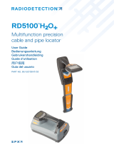
Radiodetection RD8000 Marker Locator Owner's manual

Type
Owner's manual

This manual is also suitable for

RD8000
â„¢
Radiodetection’s universal precision cable,
pipe and RF marker locator
Operation manual
90/RD8KM-OPMAN-ENG/03
© 2015 Radiodetection Ltd i
Preface
Before you begin
Thank you for your interest in Radiodetection’s
RD8000â„¢ cable, pipe and RF marker locator.
The RD8000 marker locator delivers the very latest in
cable, pipe and RF marker location technology in a
powerful yet ergonomic and light-weight design.
Please read this user manual in its entirety before
attempting to use the RD8000 system.
Radiodetection products, including this manual, are
under continuous development. The information
contained within is accurate at time of publication;
however the RD8000, this manual and all its contents
are subject to change.
Radiodetection Limited reserves the right to modify the
product without notice and some product changes may
have taken place after this user manual was published.
Contact your local Radiodetection dealer or visit
www.radiodetection.com for the latest information about
the RD8000 product family, including this manual.
Important notices
General
The performance of any cable and pipe locator may be
affected when used in close proximity to ferrous
materials such as manhole covers, steel-toe boots,
mobile phones and nearby vehicles. Keep a distance of
one or two meters from these objects when taking
critical measurements such as depth and current
readings.
This instrument, or family of instruments, will not be
permanently damaged by reasonable electrostatic
discharge and has been tested in accordance with IEC
801-2. However, in extreme cases temporary
malfunction may occur. If this happens, switch off, wait
and switch on again. If the instrument still malfunctions,
disconnect the batteries for a few seconds.
Safety
This equipment shall be used only by fully qualified and
trained personnel, and only after fully reading this
Operation Manual.
WARNING! Direct connection to live conductors is
POTENTIALLY LETHAL. Direct connections to live
conductors should be attempted by fully qualified personnel
only using the relevant products that allow connections to
energized lines.
WARNING! The transmitter is capable of outputting
potentially lethal voltages. Take care when applying signals
to any pipe or cable and be sure to notify other technicians
who may be working on the line.
WARNING! Reduce audio level before using
headphones to avoid damaging your hearing.
WARNING! This equipment is NOT approved for use
in areas where hazardous gases may be present.
WARNING! When using the transmitter, switch off the
unit and disconnect cables before removing the battery
pack.
WARNING! The RD8000 locator will detect most
buried conductors but there are some objects that do not
radiate any detectable signal. The RD8000, or any other
electromagnetic locator, cannot detect these objects so
proceed with caution. There are also some live cables
which the RD8000 will not be able to detect in Power
mode. The RD8000 does not indicate whether a signal is
from a single cable or from several in close proximity.
CAUTION: The battery dust cover, the accessory
cover and the headphones cover protects the locator’s
sockets from debris and water ingress. If they get
damaged or lost, contact Radiodetection or your local
service representative for a replacement one.
Batteries
WARNING! Batteries can get hot after prolonged use
at full output power. Take care while replacing or handling
batteries.
CAUTION: Do not tamper with, or attempt to
disassemble the battery packs.
CAUTION: If battery failure is suspected return the
entire unit to an authorized repair center for
investigation and repair. Local, national or IATA
transport regulations may restrict the shipment of faulty
batteries. Check with your courier for restrictions and
best practice guidelines. Talk to a Radiodetection sales
representative for authorized repair centers.
WARNING: Exposing the battery to a high temperature
above 60°C (140°F) may activate safety systems and
cause a permanent battery failure.
© 2015 Radiodetection Ltd ii
Battery disposal
Batteries should be disposed of in accordance with your
company’s work practice, and / or the relevant laws or
guidelines in your country or municipality.
Special Bluetooth
®
notice
RD8000 locators and transmitters contain a Class 1
Bluetooth device that can emit radio frequency energy
during the operation of certain product features. While
the Bluetooth device is busy, pairing or sending iLOC
TM
commands from the locator to the transmitter, or
sending SurveyCERTâ„¢ data, always ensure a
minimum separation of 200mm (8 inches) between the
Bluetooth antenna and your body. The location of the
antenna is shown in Section 2, figure 2.1.
Wireless technology compliance
Use of iLOC wireless technology where applicable may
be subject to national telecommunication regulations.
Check with your local government authorities for further
information.
Compliance
EU Compliance
This equipment complies with the following EU
Directives:
R&TTE Directive 1999/5/EC
Low Voltage Directive: 2006/95/EC
EMC Directive: 2004/108/EC
FCC Compliance Statement
This equipment complies with Part 15 of the FCC Rules.
Operation is subject to the following two conditions:
The equipment may not cause harmful
interference.
The equipment must accept any interference
received, including interference that may cause
undesired operation.
NOTE: This equipment has been tested and found to
comply with the limits for a Class A digital device
pursuant to Part 15 of the FCC Rules. These limits are
designed to provide reasonable protection against
harmful interference when the equipment is operated in
a commercial environment. This equipment generates,
uses, and can radiate radio frequency energy and, if not
installed and used in accordance with the
manufacturer’s instruction manual, may cause harmful
interference with radio communications. Operation of
this equipment in a residential area is likely to cause
harmful interference, in which case you will be required
to correct the interference at your own expense.
Modifications: Any modifications made to this
equipment not approved by Radiodetection may void
the authority granted to the user by the FCC to operate
this equipment.
Industry Canada Compliance Statements
ICES-003 Class A Notice:
This Class A digital apparatus complies with Canadian
ICES-003.
Avis NMB-003, Classe A: Cet appareil numérique de la
classe A est conforme à la norme NMB-003 du Canada
Training
Radiodetection provides training services for most
Radiodetection products. Our qualified instructors will
train equipment operators or other personnel at your
preferred location or at Radiodetection headquarters.
For more information go to www.radiodetection.com or
contact your local Radiodetection representative.
Copyright statement
Bluetooth word, mark and logos are registered
trademarks of Bluetooth Sig, Inc. and any use of such
trademarks by Radiodetection is under license.
Windows, Windows Vista and Windows XP are either
registered trademarks or trademarks of Microsoft
Corporation in the United States and / or other
countries.
© 2015 Radiodetection Ltd iii
© 2015 Radiodetection Ltd iv
© 2015 Radiodetection Ltd v
Contents
Section 1 - Introduction .................................................. 1
1.1 About this manual ................................................ 1
1.1.1 Additional documentation .............................. 1
1.2 About the RD8000................................................ 1
1.3 Extended Warranty .............................................. 1
1.4 Manual outline ...................................................... 1
1.5 Safety ................................................................... 1
Section 2 - System overview ......................................... 4
2.1 RD8000 marker locator ........................................ 4
2.1.1 Locator features ............................................ 4
2.1.2 Locator keypad .............................................. 4
2.1.3 Locator screen icons ..................................... 4
2.2 Tx-1, Tx-5 and Tx-10 transmitters ........................ 5
2.2.1 Transmitter features ...................................... 5
2.2.2 Transmitter keypad ........................................ 6
2.2.3 Transmitter screen icons ............................... 6
2.3 Using the menu .................................................... 6
2.3.1 Navigating the locator menu.......................... 6
2.3.2 Locator menu options .................................... 6
2.3.3 Navigating the transmitter menu ................... 7
2.3.4 Transmitter menu options .............................. 7
Section 3 - Operation ..................................................... 8
3.1 First use ............................................................... 8
3.2 Powering up ......................................................... 8
3.2.1 Power Options ............................................... 8
3.3 Shutting down .................................................... 10
3.4 System setup ..................................................... 10
3.4.1 Language ..................................................... 10
3.4.2 Battery type ................................................. 10
3.4.3 Power frequency (locator only) .................... 11
3.4.4 Measurement Units (locator only) ............... 11
3.4.5 Enable / Disable frequencies ....................... 11
3.4.6 Marker locator.............................................. 11
3.4.7 Volume Control ............................................ 12
3.5 Dynamic overload protection
TM
.......................... 12
3.6 TruDepthâ„¢ measurement ................................. 12
3.7 Passive avoidance ............................................. 12
3.8 StrikeAlert
â„¢
........................................................ 12
3.9 Antenna modes .................................................. 12
3.10 Backlight ........................................................... 13
3.11 Bluetooth wireless ............................................ 13
3.12 iLOC and SideStep ........................................... 13
3.13 SideStepauto
â„¢
.................................................. 13
3.13.1 Using SideStepauto ................................... 13
3.14 Transmitter power output.................................. 13
3.14.1 Adjusting power output .............................. 13
3.14.2 Boost (Tx-10(B) only) ................................. 13
3.15 Transmitter Eco mode ...................................... 14
3.16 Measure mode .................................................. 14
3.16.1 Impedance and voltage measurements..... 14
3.16.2 Impedance measurements using active
frequency .............................................................. 14
3.17 CALSafe ........................................................... 15
3.18 Automatic Logging ............................................ 15
3.19 GPS .................................................................. 15
3.19.1 GPS menu ................................................. 15
3.19.2 Internal GPS .............................................. 15
Section 4 - Locating cables and pipes ......................... 17
4.1 Frequencies ........................................................ 17
4.1.1 Passive frequencies ..................................... 17
4.1.2 Active frequencies ........................................ 17
4.1.3 Selecting Frequencies ................................. 18
4.2 Antenna modes .................................................. 18
4.2.1 Peak mode ................................................... 18
4.2.2 Single antenna mode ................................... 18
4.2.3 Null mode ..................................................... 18
4.2.4 Combined Peak / Null mode ........................ 19
4.2.5 Guidance mode ............................................ 19
4.3 Compass............................................................. 19
4.4 Trace ................................................................... 19
4.5 Pinpoint ............................................................... 19
4.6 Sweep and search .............................................. 20
4.6.1 Passive Sweep ............................................ 20
4.6.2 Inductive search ........................................... 20
Section 5 - Locating RF Markers.................................. 22
5.1 Marker Mode ...................................................... 22
5.1.1 Entering Marker mode ................................. 22
5.1.2 Changing RF marker type ............................ 22
5.1.3 Combined mode ........................................... 23
5.2 Locating RF markers .......................................... 23
5.2.1 Single mode locating.................................... 23
5.2.2 Combined mode locating ............................. 23
Section 6 - Depth and current readings ....................... 24
© 2015 Radiodetection Ltd vi
6.1 TruDepthâ„¢ ......................................................... 24
6.1.1 TruDepth for RF Markers ............................. 24
6.1.2 TruDepth for buried conductors or sondes .. 24
6.2 Verifying depth measurements .......................... 25
6.2.1 Rough depth calibration check .................... 25
6.3 Current Readings ............................................... 26
6.3.1 Identification using current measurements .. 26
6.3.2 About current measurements ...................... 26
6.3.3 Applying a transmitter signal ....................... 26
6.3.4 Signal current measurements ...................... 26
Section 7 - General Locating tips ................................. 28
7.1 Eliminating services ............................................ 28
7.1.1 Induction ...................................................... 28
7.1.2 Unwanted signal coupling ............................ 28
7.2 Signal grounding ................................................ 29
7.2.1 Manhole covers ........................................... 29
7.2.2 Using lighting columns ................................. 29
7.2.3 Finding a good ground point ........................ 29
7.3 Double-ended connections................................. 29
7.3.1 Making a double-ended connection............. 29
Section 8 - Using Accessories ..................................... 30
8.1 About accessories .............................................. 30
8.2 Headphones ....................................................... 30
8.3 Locator clamps ................................................... 30
8.3.1 When to use clamps .................................... 30
8.3.2 Connecting a clamp ..................................... 30
8.3.3 Available locator clamps .............................. 30
8.4 Transmitter clamps ............................................. 31
8.4.1 Connecting the clamp .................................. 31
8.4.2 Available transmitter clamps ........................ 32
8.5 Sondes ............................................................... 33
8.5.1 What is a Sonde .......................................... 33
8.5.2 Choosing a suitable sonde .......................... 33
8.5.3 Preparation .................................................. 33
8.5.4 Propelling a sonde ....................................... 33
8.5.5 Locating and tracing a sonde ...................... 33
8.5.6 Checking sonde depth ................................. 34
8.5.7 FlexiTrace .................................................... 34
8.6 Stethoscopes ...................................................... 35
8.6.1 When to use a stethoscope ......................... 35
8.6.2 How to use a stethoscope ........................... 35
8.6.3 Types of stethoscope .................................. 35
8.7 Submersible antenna ......................................... 35
8.7.1 When to use a submersible antenna .......... 35
8.7.2 How to use a submersible antenna ............. 35
Section 9 - Fault-Finding ............................................. 37
9.1 About fault-finding .............................................. 37
9.2 Preparation ........................................................ 37
9.2.1 Connecting the transmitter .......................... 37
9.2.2 Reference readings ..................................... 37
9.3 How to find a fault .............................................. 38
Section 10 - Current direction (CD) ............................. 39
10.1 Understanding CD ........................................... 39
10.1.1 Using Current Direction (CD) to aid line
identification ......................................................... 39
10.2 CD Reset ......................................................... 39
10.2.1 About CD reset .......................................... 39
10.2.2 Using a CD clamp or stethoscope ............ 40
10.2.3 Performing a CD reset .............................. 40
Section 11 - Survey measurements ............................ 41
11.1 Saving measurements ..................................... 41
11.2 Survey measurement transmission over
Bluetooth .................................................................. 41
11.3 Erasing measurements .................................... 41
11.4 SurveyCERT .................................................... 41
Section 12 - Bluetooth wireless connections ............... 43
12.1 Switching Bluetooth On ................................... 43
12.2 Switching Bluetooth off .................................... 43
12.3 Pairing to a transmitter ..................................... 43
12.4 Pairing to a PDA .............................................. 43
12.4.1 Connection requirements .......................... 43
12.4.2 Pairing ....................................................... 44
12.5 Bluetooth Protocol ........................................... 44
12.6 Bluetooth Range .............................................. 44
12.6.1 Long Range settings ................................. 44
12.6.2 Standard Range settings........................... 44
12.7 Bluetooth Connection mode ............................ 45
12.8 Troubleshooting ............................................... 45
12.8.1 Resetting connections ............................... 45
12.8.2 Bluetooth error codes ................................ 46
Section 13 - iLOC ........................................................ 47
13.1
Using
iLOC ....................................................... 47
13.1.1 Changing frequencies ............................... 47
13.1.2 Adjusting power ......................................... 47
13.1.3 Sleep / wake the transmitter...................... 47
© 2015 Radiodetection Ltd vii
13.1.4 SideStep .................................................... 48
Section 14 - Appendices .............................................. 49
14.1 Care and maintenance ..................................... 49
14.1.1 General ...................................................... 49
14.1.2 Batteries and power supply ....................... 49
14.1.3 Cleaning .................................................... 49
14.1.4 Disassembly .............................................. 49
14.1.5 Service and maintenance .......................... 49
14.2 Time and Date error messages ....................... 49
14.3 Warranty and extended warranty ..................... 49
14.3.1 Registering using e-mail ............................ 50
14.4 RD Managerâ„¢ ................................................. 50
14.5 Upgrading software .......................................... 50
14.6 eCert ................................................................ 50
14.7 System Specifications ...................................... 51
14.8 Supported frequencies ..................................... 52
14.8.1 Sonde Frequencies ................................... 52
14.8.2 Passive Frequencies ................................. 52
14.8.3 CD Frequency Pairs .................................. 52
14.8.4 Active Frequencies .................................... 53
14.9 RF Markers ...................................................... 54
14.10 Supported accessories .................................. 54
© 2015 Radiodetection Ltd 1
Section 1 - Introduction
1.1 About this manual
This manual provides cable and pipe survey
professionals with comprehensive operating instructions
for the RD8000 locator and transmitter system. Before
operating the RD8000 system it is very important that
you read this manual, noting all safety warnings and
procedures.
1.1.1 Additional documentation
The RD Manager and SurveyCERT manuals are
available to download from www.radiodetection.com.
1.2 About the RD8000
The RD8000 system provides the user with fast,
effective means of locating and mapping buried utilities.
The RD8000 product family offers a comprehensive
range of locators and transmitters designed to meet
specific customer needs.
The RD8000 marker locator is ergonomically designed
to provide the operator with a balanced, light weight tool
that encourages extended use in most environments.
The RD8000 range of transmitters and locators offers a
wide range of accessories designed to enhance the
performance and to add extra functionalities.
For more information about the Precision Locate
Accessories Range visit www.radiodetection.com
1.3
Extended Warranty
RD8000 Marker locators and transmitters are covered
by a 1 year warranty as standard.
Customers can extend the warranty period to a total of 3
years by registering their products (locators and
transmitters) within 3 months from purchase.
Registration is performed using the RD Manager PC
software. See section 14.3 for further details
NOTE: You can also register your products by e-mail.
See section 14.2 for more details
From time to time Radiodetection may release new
software to improve the performance or add new
functionalities to his products. By registering the user
will benefits from subscribing to e-mail alerts advising
about any new software and special offers related to its
product range.
Users will be able to opt out at any moment from
receiving software and technical notifications or just
from receiving marketing material.
1.4 Manual outline
Section 1 includes an overview of safety procedures
and notices. Please review them before moving on to
Section 2 and the rest of this manual
Section 2 provides an overview of the RD8000 system
with annotated diagrams of the locator and transmitter
Section 3 introduces basic setup and operation using
the RD8000 locator’s menu system.
Section 4 introduces the survey storage capabilities of
the locator. At a touch of a button your locator will store
in its internal memory up to 1000 survey points for easy
reporting and integration to GIS / Mapping systems
Section 5 provides instructions on how to use the
RD8000 locator’s Bluetooth technology to pair to
external devices.
Section 6 introduces iLOC, Radiodetection’s advanced
remote control technology that allows you to control a
Bluetooth transmitter (Tx-5B or Tx-10B) using the
RD8000 Marker locator.
Section 7 introduces the theory and practice of cable
and pipe location using the RD8000 marker locator and
transmitter.
Section 8 provides instructions on locating RF markers
Section 9 introduces depth and current readings.
Section 10 provides general locating tips.
Section 11 introduces the range of accessories that are
compatible with the RD8000 system.
Section 12 introduces cable sheath fault-finding using
the RD8000 marker locator and an accessory A-frame.
Section 13 introduces current direction (CD) mode.
Section 14 includes several appendices with reference
material and other technical information.
1.5 Safety
Please read this manual in its entirety before attempting
to operate the RD8000 locator or transmitter. Note all
safety notices in the preface and throughout this
manual.
Follow your company and national safety procedures
and or requirements when operating this equipment in
any environment or workplace. If you are unsure what
policies or procedures apply, contact your company or
site’s occupational health and safety officer or your local
government for more information.
Do not use this equipment if you suspect that any
component or accessory is damaged or faulty.
© 2015 Radiodetection Ltd 2
Use authorized accessories only. Incompatible
accessories may damage the equipment or give
inaccurate readings.
Do not use iLOC or Bluetooth in areas where wireless
communication devices are considered hazardous.
Check local authorities for more information.
Keep this equipment clean and arrange for regular
services with an authorized Radiodetection service
center. More information can be found in the Appendix
or from your local Radiodetection representative.
Do not attempt to open or dismantle any part of this
equipment unless directed specifically by this manual.
Doing so may render the equipment faulty and may void
the manufacturer’s warranty.
A risk assessment of digging activities is recommended
prior to commencing. We cannot be held liable for
inaccurate surveys or consequential damages.
© 2015 Radiodetection Ltd 3
Figure 2.1: RD8000 Marker Locator
Figure 2.2: Locator keypad
Figure 2.3: Locator LCD display
© 2015 Radiodetection Ltd 4
Section 2 - System overview
2.1 RD8000 marker locator
2.1.1 Locator features
1 Keypad
2 LCD with auto backlight
3 Speaker
4 Battery compartment
5 Battery charger socket
6 Accessory socket
7 Headphone socket
8 Bluetooth module antenna
9 Marker loop antenna
2.1.2 Locator keypad
10 Power key : Switches the unit on and off. Opens
the locator menu
11 Frequency key : Selects frequency. Closes
submenu
12 Up and down arrows : Adjusts the signal gain.
Scrolls through the menu options
13 Antenna key : With antenna folded up, toggles
peak, combined peak / null, null, single antenna and
guidance modes. With antenna folded down,
toggles marker and combined (marker / line)
modes. Opens a submenu
14 Graph key : Saves Survey measurements
15 Transmitter key : Sends iLOC commands to
Bluetooth transmitters
2.1.3 Locator screen icons
16 Indicates the signal strength and peak marker
17 Signal strength: Numerical indication of signal
strength
18 Peak / Proportional arrows: Indicates the location of
the line relative to the locator
19 Battery icon: Indicates the battery level
20 Sensitivity and Log number: Displays the log
number momentarily after a survey measurement is
saved to memory
21 Volume icon: Displays the volume level
22 Current Direction arrows
23 Radio Mode: Indicates when Radio Mode is active
24 Power Mode: Indicates when Power Mode is active
25 Accessory indicator: Indicates when an accessory is
connected
26 CD Mode icon: Indicates when Current Direction
Mode is active
27 A-Frame icon: Indicates when the A-Frame is
connected
28 Operating mode indicator
29 Bluetooth icon: Indicates status of Bluetooth
connection. Flashing icon means pairing is in
progress. Solid icon indicates an established
connection is active
30 Antenna mode icon: Indicates antenna selection:
Peak, Null, Single, combined Peak / Null and
Guidance Mode
31 Sonde icon: Indicates that the signal source is from
a sonde
32 Line icon: Indicates that the signal source is from a
line
33 Compass / Marker mode indicator: Shows the
direction of the located cable relative to the locator.
Also used as a graphical indication for Marker mode
active
34 Tx status (with Bluetooth Tx models): Displays
transmitter connection status
35 Tx standby (with Bluetooth Tx models): Indicates
that the transmitter is in Standby Mode
36 Current / depth indicator
37 GPS Status icon (GPS models only): One bar
indicates that GPS is active. 3 bars indicates that
the GPS has locked to the GPS satellite system
38 GPS Signal quality icon (GPS models only):
Indicates the quality of the signal being received
© 2015 Radiodetection Ltd 5
2.2 Tx-1, Tx-5 and Tx-10
transmitters
2.2.1 Transmitter features
1 Keypad
2 LCD
3 Removable accessory tray
4 D-cells battery holder
5 Rechargeable battery pack (Optional)
Figure 2.4 Tx Transmitter
Figure 2.6 Rechargeable battery pack
Figure 2.6: Tx Transmitter keypad
Figure 2.7 Tx Transmitter LCD
Figure 2.5 D-cells battery holder
© 2015 Radiodetection Ltd 6
2.2.2 Transmitter keypad
6 Power key : Switches the unit on and off. Opens
the transmitter menu
7 Frequency key : Selects frequency. Menu
navigation key
8 Up and down arrows : Adjusts the output
signal. Scrolls through the menu options
9 Measure key : Opens a sub menu. Used to take
voltage and impedance measurements.
2.2.3 Transmitter screen icons
10 Battery icon: Indicates the battery level
11 Alphanumeric description of selected operation
mode
12 Standby icon: Appears when the transmitter is in
Standby Mode
13 Output level: Displays transmitter output power
14 Accessory or Measurement indicators: Indicates if
an accessory is connected or if measure mode is
active
15 DC icon: Appears when the transmitter is powered
from a DC source
16 Induction indicator: Appears when the transmitter is
in Induction Mode
17 A-Frame (Tx-5(B) or Tx-10(B) only): Indicates when
the transmitter is in Fault-Find Mode
18 CD Mode indicator (Tx-10(B) only): Indicates that
the transmitter is in Current Direction Mode
19 Voltage warning indicator: Indicates that the
transmitter is outputting potentially hazardous
voltage levels
20 Volume icon: Displays the volume level
21 Pairing icon (Tx-5B or Tx-10B only): Appears when
the transmitter and locator are connected via iLOC
22 Bluetooth icon (Bluetooth Tx models): Indicates
status of Bluetooth connection. A flashing icon
means pairing is in progress
2.3 Using the menu
The RD8000 locator and transmitter menus allow you to
select or change system options. Once entered, the
menu is navigated using the arrow keys. Navigation is
consistent on both the transmitter and the locator. In the
menu the options will appear in the bottom left-hand
corner of the display. Note that when browsing the
locator menu, the and keys act as left and right
arrows. When browsing the transmitter menu the and
keys act as left and right arrows. The right arrow
enters a submenu and the left arrow selects the option
and returns to the previous menu.
2.3.1 Navigating the locator menu
1 Press the key to enter the menu
2 Use the or keys to scroll through the menu
options
3 Press the key to enter the option's submenu
4 Use the or arrows to scroll through the
submenu options
5 Press the key to make a selection and return to
the previous menu
6 Press the key to return to the main operation
screen
2.3.2 Locator menu options
Below is an annotated list of menu options available in
the RD8000 locator.
VOL
Adjust the speaker volume from 0
(mute) to 3 (loudest)
LOG
Delete or send saved survey
measurements data and enable or
disable the communication channel
BT
Enable, disable, reset or pair
Bluetooth connections. Also defines
the protocol used when connecting
to a PDA
GPS
Select an external GPS module or
enable or disable the internal one –
RD8000 locators (GPS models
only)
CDR
CD Reset – Only available when in
CD mode
UNITS
Select metric or imperial units
CAL
Displays the date of the last
calibration or eCert calibration
validation
MARKR
Enable or disable the marker
locator or individual utility markers
LANG
Select menus language
POWER
Select power frequency: 50 or 60Hz
ANT
Enable or disable antenna modes
with the exception of Peak
FREQ
Enable or disable individual
frequencies
ALERT
Enable or disables StrikeAlert
BATT
Set battery type: ALK, NIMH or
LIION
COMP
Enable or disable display of the
Compass feature.
© 2015 Radiodetection Ltd 7
2.3.3 Navigating the transmitter menu
1 Press the key to enter the menu
2 Use the or keys to scroll through the menu
options
3 Press the key to enter the option’s submenu.
4 Use the or keys to scroll through the
submenu options
5 Press the key to confirm selection and return to
the previous level or exit the menu
6 Press the key to return to the main operation
screen
2.3.4 Transmitter menu options
Below is an annotated list of menu options available in
the RD8000 transmitter.
Adjust the speaker volume from 0
(mute) to 3 (loudest)
FREQ
Enable or disable individual
frequencies
BOOST
Boost transmitter output for a
specified period of time (in minutes)
LANG
Select menus language
OPT F
Enable or disable SideStepauto
BATT
Set battery type: ALK, NIMH or LIION
– Also select Eco mode for alkaline
batteries only
MAX P
Allows the transmitter to output its
maximum wattage
MODEL
Specify the model of your locator
MAX V
Set the output voltage
BT
Enable, disable or pair Bluetooth
connections (Bluetooth models
only)
© 2015 Radiodetection Ltd 8
Section 3 - Operation
3.1 First use
For safety reasons, RD8000 locators are shipped with
the Lithium-ion battery packs disconnected. The
transmitter D-cells and the optional Li-ion battery pack
are packed separately.
On the locator:
To connect the Li-ion battery pack open the RD8000
battery compartment and plug the battery lead into the
battery connector.
On the transmitter:
To fit the D-cells batteries in the transmitter, unlatch the
accessory tray. The battery compartment is located
underneath the transmitter body. Use the turnkey to
unlatch the battery compartment. Insert eight D-Cell
Alkaline or NiMH batteries.
3.2 Powering up
To switch the locator or the transmitter on, press the
key.
When you power up the locator or transmitter, they will
perform an LCD segment check. It will then display the
model number followed by the software version. This
information is important if you need to contact
Radiodetection technical support or update your locator
to the latest software.
3.2.1 Power Options
The RD8000 marker locator range is provided with a
rechargeable Lithium-ion (Li-ion) battery pack as
standard. The locator can also be powered using good
quality D-cell alkaline or NiMH-batteries.
Transmitters can be powered by D-cell alkaline batteries
(as standard), D-cell NiMH batteries, or by an optional
accessory Li-ion battery pack. Alternatively, you can
power the transmitter from a mains or vehicle power
source using a Radiodetection supplied optional
accessory adapter.
Battery status
The locator and transmitter display provides a battery
level indicator (refer to the diagrams in Sections 2.1 and
2.2). When battery replacement is necessary, the
display shows a flashing battery icon.
Refer to appendix 14.6 for some indicative operating
times.
NOTE: Prolonged use of high power output on the
transmitter will reduce battery life.
You must fully charge your locator and optional
transmitter battery pack before their first use
Recharging the locator Li-ion battery pack
To recharge the locator battery pack, connect the
battery charger to the DC input connector on the front of
the battery pack.
Figure 3.1 Li-ion battery pack connection
Figure 3.2 Charging the locator Li-ion battery pack
© 2015 Radiodetection Ltd 9
For more information about recharging batteries refer to
the instructions that came with your charger.
WARNING! Do not heat the rechargeable battery pack
above 60°C (140°F) as this will damage the battery’s
thermal fuses.
Recharging the transmitter Li-ion battery pack
To recharge the battery pack, remove the pack from the
transmitter and connect the transmitter battery charger.
Figure 3.3 Charging the transmitter Li-ion battery pack
For more information about recharging batteries refer to
the instructions that came with your charger
Using the D-cell locator battery holder
The locator can also be powered by three D-Cell
Alkaline or NiMH batteries.
NOTE: When installing batteries always observe the
correct battery polarity as indicated on the battery tray.
Figure 3.4 Locator D-cell holder
To insert the D-cells:
1 Open the cell tray and insert 1 D-cell
2 Close the tray and insert 2 D-cells
To remove / fit a battery holder:
1 Open the battery compartment using the
release catch
2 Un-plug the battery lead connector (fig.3.1)
3 Lift the accessory cover slightly (fig 3.5)
Figure 3.5 Lifting accessory cover
© 2015 Radiodetection Ltd 10
4 Press the battery retaining latch inwards (fig
3.6)
Figure 3.6 Pressing retaining latch
5 Rotate the battery pack away and up from the
latch (fig3.7)
Figure 3.7 Rotating the battery pack
6 Repeat on the other side to release the battery
pack completely
To fit the battery holder follow the steps above in
reverse order.
Transmitters, all models
To replace the batteries on the transmitter, unlatch the
accessory tray. The D-Cell battery tray (see figure 3.4
on page 17) is located underneath the transmitter body.
Use the turnkey to unlatch the battery compartment.
Remove the spent batteries and insert eight D-Cell
Alkaline or NiMH batteries.
3.3 Shutting down
To switch the locator or transmitter off, press and hold
the key until the screen blanks off.
NOTE: The locator will automatically power off if no
keys are pressed after a five minute duration.
3.4 System setup
The RD8000 locator and transmitter settings can be
accessed via the menu. Once in the menu it is possible
to change settings according to your personal
preferences and operating requirements. Some
examples of setting changes are shown below.
Please refer to the locator and transmitter menu options
for more information.
NOTE: These procedures refer to both the transmitter
and locator unless stated otherwise.
Before changing settings, ensure the locator or
transmitter is switched on by pressing the key for two
seconds.
3.4.1 Language
The locator and transmitter support a number of
languages. You can specify your preferred language
using the menu system.
To select your preferred menu language:
1 Press the key to enter the menu
2 Scroll to the LANG menu using the or keys
3 Press the key (on the locator) or the key (on
the transmitter) to enter the LANG menu
4 Scroll up or down to select your preferred language
5 Press the key to accept your selection and return
to the main menu.
6 Press the key to return to the main operation
screen.
3.4.2 Battery type
RD8000 locators and transmitters support Li-ion,
Alkaline or NiMH batteries.
By default your RD8000 locator battery type is set to Li-
ion.
It is important that you set the system to match the
currently installed battery type to ensure optimal
performance and correct battery level indication.
To set your battery type:
1 Press the key to enter the menu
2 Scroll to the BATT menu using the or arrows
3 Press the key ( on the locator) or the key (on
the transmitter) to enter the BATT menu
4 Scroll up or down to select the correct battery type
5 Press the key to accept your selection and return
to the main menu
© 2015 Radiodetection Ltd 11
6 Press the key to return to the main operation
screen
3.4.3 Power frequency (locator only)
Select the correct frequency (50 or 60Hz) for your
country or region’s power supply.
To change power frequency on the locator:
1 Press the key to enter the menu
2 Scroll to the POWER menu using the or keys
3 Press the key to enter the POWER menu
4 Scroll up or down to select the correct frequency
5 Press the key to accept your selection and return
to the main menu
6 Press the key to return to the main operation
screen
3.4.4 Measurement Units (locator
only)
The RD8000 marker locator allows you to work in Metric
or Imperial (US customary) units.
To select your preferred units:
1 Press the key to enter the menu
2 Scroll to the UNITS option using the or keys
3 Press the key to enter the UNIT submenu
4 Scroll up or down to select METRE (for metric) or
IMP (for imperial)units
5 Press the key to accept your selection and return
to the main menu
6 Press the key to return to the main operation
screen
3.4.5 Enable / Disable frequencies
The locator and transmitter support a wide range of
frequencies and there may be times when some of
these frequencies are not used. It is possible to quickly
enable or disable frequencies using the menu system.
To enable or disable frequencies:
1 Press the key to enter the menu
2 Scroll to the FREQ menu using the or keys
3 Press the key (on the locator) or the key (on
the transmitter)to enter the FREQ menu
4 Scroll up or down to select the frequency
5 Press the key (on the locator) or the key (on
the transmitter)to enter the frequency
6 Scroll to OFF or ON using the or keys
7 Press the key to accept your selection and return
to frequency menu.
8 If you wish to make any further changes follow
steps 4 to 6. If you do not wish to make any further
changes press the key twice to return to the main
operation screen.
3.4.6 Marker locator
By default the marker locator is enabled or disabled by
lowering or folding the marker loop antenna, item 9 in
Section 2, figure 2.1
You can choose to disable the marker locator function.
To disable the marker locator:
1 Press the key to enter the menu
2 Scroll to the MARKR menu using the or keys
3 Press the key to enter the MARKR menu
4 Scroll to OFF menu
5 Press the key to accept your selection and return
to MARKR menu
If you have disabled the marker locator you can enable
it again.
To enable the marker locator:
1 Press the key to enter the menu
2 Scroll to the MARKR menu using the or keys
3 Press the key to enter the MARKR menu
4 Scroll to Auto menu
5 Press the key to accept your selection and return
to MARKR menu
The marker locator can detect up to 9 different utility
markers. If you wish you can enable or disabling them
by using the menu system:
To enable or disable utility markers:
1 Press the key to enter the menu
2 Scroll to the MARKR menu using the or keys
3 Press the key to enter the MARKR menu
4 Scroll to the AUTO menu and press the key
5 Scroll up or down to select a specific marker
6 Press the key
7 Scroll to OFF or ON using the or keys
8 Press the key to accept your selection and return
to markers menu
9 If you wish to make any further changes follow
steps 5 to 8. If you do not wish to make any further
  • Page 1 1
  • Page 2 2
  • Page 3 3
  • Page 4 4
  • Page 5 5
  • Page 6 6
  • Page 7 7
  • Page 8 8
  • Page 9 9
  • Page 10 10
  • Page 11 11
  • Page 12 12
  • Page 13 13
  • Page 14 14
  • Page 15 15
  • Page 16 16
  • Page 17 17
  • Page 18 18
  • Page 19 19
  • Page 20 20
  • Page 21 21
  • Page 22 22
  • Page 23 23
  • Page 24 24
  • Page 25 25
  • Page 26 26
  • Page 27 27
  • Page 28 28
  • Page 29 29
  • Page 30 30
  • Page 31 31
  • Page 32 32
  • Page 33 33
  • Page 34 34
  • Page 35 35
  • Page 36 36
  • Page 37 37
  • Page 38 38
  • Page 39 39
  • Page 40 40
  • Page 41 41
  • Page 42 42
  • Page 43 43
  • Page 44 44
  • Page 45 45
  • Page 46 46
  • Page 47 47
  • Page 48 48
  • Page 49 49
  • Page 50 50
  • Page 51 51
  • Page 52 52
  • Page 53 53
  • Page 54 54
  • Page 55 55
  • Page 56 56
  • Page 57 57
  • Page 58 58
  • Page 59 59
  • Page 60 60
  • Page 61 61
  • Page 62 62
  • Page 63 63
  • Page 64 64
  • Page 65 65
  • Page 66 66
  • Page 67 67

Radiodetection RD8000 Marker Locator Owner's manual

Type
Owner's manual
This manual is also suitable for

Ask a question and I''ll find the answer in the document

Finding information in a document is now easier with AI