Page is loading ...

Installation, Operation and Maintenance Instructions
M077910
Issue 4
March 2020
Xsafe Bright
Gas Detectors with Display and Relays


Contents
1. Introduction .............................................................................. 1
1.1 Product overview .............................................................. 1
1.2 Safety information ............................................................ 1
1.3 Storage instructions .......................................................... 2
1.4 Product labels ................................................................... 2
1.5 Product dimensions .......................................................... 3
1.6 Exploded view .................................................................. 4
2. Installation ................................................................................ 5
2.1 Location ........................................................................... 5
2.2 Mounting ......................................................................... 6
2.3 Internal Electrical Connections .......................................... 6
2.4 General Cabling Requirement .......................................... 7
2.5 Cabling Requirement 4 to 20 mA Current Loop ............... 7
2.6 Cabling Requirement Multidrop MODBUS ........................ 8
2.6.1 Calculating acceptable cable length and detector
quantities ................................................................. 9
2.7 Earthing requirements .................................................... 12
2.8 Cable glands .................................................................. 12
2.9 Fitting accessories ........................................................... 15
3. Operation ............................................................................... 16
3.1 Operation panel ............................................................. 16
3.2 Key Operation ................................................................ 16
3.3 Start up .......................................................................... 17
3.4 Menu functions .............................................................. 18
3.5 Zero ............................................................................... 19
3.6 Calibrate ....................................................................... 19
3.7 Routine maintenance ..................................................... 20
3.8 Sensor replacement ........................................................ 20
3.9 IR Carbon Dioxide .......................................................... 21
3.10 PID ................................................................................. 22
3.11 Maintenance and cleaning of the PID sensor: ................. 22

4. Specifications .......................................................................... 24
5. Spare parts ............................................................................. 25
6. Warranty ................................................................................ 26
Appendix ...................................................................................... 28

1
English
1. Introduction
1.1 Product overview
Xsafe Bright is a versatile gas detector for monitoring a wide range of
flammable and toxic gases and oxygen levels. Xsafe Bright incorporates a
bright OLED (organic light emitting diode) display and a magnetic wand for
easy menu operation.
Xsafe Bright provides analogue 4-20mA and RS-485 Modbus signals as
standard, with optional HART interface. Relays are also fitted for activating local
alarms or sending digital signals to control systems.
Xsafe Bright may be fitted with electrochemical type toxic or oxygen sensors,
PID sensors or infrared (IR) carbon dioxide gas sensors. Please refer to the
product identification label to determine the type of sensor fitted.
Xsafe Bright has no hazardous location capability. It may not be installed in a
zoned hazardous location. For such applications Xgard Bright is advised.
1.2 Safety information
Safety information relevant to Ex requirements:
• The cable gland must be installed before use and must have an appropriate
ingress protection for the application and environment.
• Unused cable entries must be sealed to give appropriate ingress protection.
• Only cables of types specific in these instructions can be used.
General safety information
• Xsafe Bright gas detectors must be installed, operated and maintained in
strict accordance with these instructions, warnings, label information, and
within the limitations stated.
• Xsafe Bright detectors are designed to detect gases or vapours in air, and
not inert or oxygen deficient atmospheres. Xsafe Bright oxygen detectors
can measure in oxygen deficient atmospheres. The exception is carbon
dioxide Xsafe Bright which uses infrared technology and will work with no
oxygen present.
• Electrochemical cells used in toxic and oxygen versions of Xsafe Bright
contain small volumes of corrosive electrolyte. Care should be observed
when replacing cells to ensure that the electrolyte does not come into
contact with skin or eyes.

Introduction
2
English
• Maintenance and calibration operations must only be performed by
qualified service personnel.
• Only genuine Crowcon replacement parts must be used, substitute
components may invalidate the warranty of the detector.
• Xsafe Bright detectors must be protected from extreme vibration, and
direct sunlight in hot environments as this may cause the temperature of
the detector to rise above its specified limits and cause premature failure. A
sunshade is available for Xsafe Bright.
1.3 Storage instructions
Some types of sensor available with Xsafe Bright have limited life when left
un-powered and/or may be adversely affected by temperature extremes or
environmental contamination. Ideal storage conditions are 20˚C and 60%RH.
It is strongly recommended detectors are installed and powered within 3
months of purchase.
1.4 Product labels
CE 1180,
Xsafe Bright
Crowcon Detection Instruments Limited
172 Brook Drive, Milton Park, Abingdon, OX144SD

Introduction
3
English
1.5 Product dimensions
All dimensions in millimetres
Diagram 1: Xsafe Bright dimension view

Introduction
4
English
1.6 Exploded view
Diagram 2: Xsafe Bright exploded view

5
English
2. Installation
WARNING
This detector is designed for use in safe areas. It is not to be used in
EX hazardous locations. Installation must be in accordance with the
recognized standards of the appropriate authority in the country
concerned. For further information please contact Crowcon. Prior to
carrying out any installation work ensure local regulations and site
procedures are followed.
2.1 Location
The detector should be mounted where the gas to be detected is most likely to
be present. The following points should be noted when locating gas detectors:
• To detect gases which are lighter than air, detectors should be mounted at
high level and Crowcon recommend the use of a collector cone (Part No.
C01051).
• To detect heavier than air gases, e.g. carbon dioxide, detectors should be
mounted at low level.
• When locating detectors consider the possible damage caused by natural
events e.g. rain or flooding. For detectors mounted outdoors Crowcon
recommend the use of a Spray Deflector (Part No. C01052).
• Consider ease of access for functional testing and servicing.
• Consider how the escaping gas may behave due to natural or forced air
currents. Mount detectors in ventilation ducts if appropriate.
• Consider the process conditions. For example, carbon dioxide is normally
heavier than air, but if released from a process which is at an elevated
temperature and/or pressure, the gas may rise before falling.
• Location of oxygen sensors requires knowledge of the gas that may
displace the oxygen. For example, carbon dioxide is denser than air and
therefore is likely to displace oxygen from low levels upwards.
• Sensors should be mounted at head height (1.5m nominally) to detect
gases of a similar density to air, assuming that ambient conditions and the
temperature of the target gas are nominally 20˚C.
The placement of sensors should be determined following advice of experts
having specialist knowledge of gas dispersion, the plant processing equipment
as well as safety and engineering issues. The agreement reached on the
locations of sensors should be recorded.

Installation
6
English
2.2 Mounting
Xsafe Bright should be installed at the designated location with the sensor
pointing down. This ensures that dust or water will not collect on the sensor
and stop gas or solvents being measured entering the cell. Care should be
taken when installing the detector to avoid damaging the painted surface of
the enclosure. There are two M20x1.5 entry ports on the base. One entry port
will be used for power supply input during normal operation. Unused port will
be blocked by blind plug, or can be used to connect external alarm device or
be used for connecting devices to the multi-drop communications.
Note: Please avoid direct water jets into the sensors, as it is likely to lead to
damage.
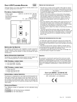
2.3 Internal Electrical Connections
Diagram 3: Xsafe Bright internal electrical connections
B A B A
SINK
485
4-20mA LOOP
SIG
–
+
SOURCE
Fault
Level2
Level1
SOUNDER OUT
NO
NC
RT
NO
NC
NO
NC
Vmax=30V Wmax=3W
Xgard Bright Gas Detector
Sounder Out
Power and Loop Connector
Production
use only
Production use
only
NOT USB!
Alarm level 2
Relay Output
Alarm Level 1
Relay Output
Alarm Level 1
NO/NC Jumper
Selection
SOURCE/SINK
Jumpers Fitted to
LHS = SINK, see
lengend on board
RS485 IN/OUT
or End of Line
Terminator
Alarm Level 2
NO/NC Jumper
Selection
Lower Board
Sensor
Connector
Lower Board
Programming
Connector
Fault NO/NC
Jumper Selection
Fault Relay
Output

Installation
7
English
NOTE: the mini USB socket is not intended for customer use,
connecting this to a computer is likely to damage both Xsafe Bright
and the computer.
2.4 General Cabling Requirement
Cabling to Xsafe Bright must be in accordance with the recognised standards
of the appropriate authority in the country concerned and meet the electrical
requirements of the detector.
2.5 Cabling Requirement 4 to 20 mA Current Loop
Fulfils the requirements for 4 to 20 mA current loop and HART connections,
allows for connection and powering of accessory beacon or sounder subject to
current consumption, cable resistance and panel voltage. Current consumption
should consider worst case e.g. when the accessories are powered.
Example Calculation 1
What is the longest cable for a Bright to operate using point to point
connection and powering a sounder with 250mA current consumption.
Use parameters of 1.5mm2 cable, where the controller has a guaranteed
minimum output voltage of 18V.
This type of cable has resistance of 12.1Ω/km, therefore the there and back
cable resistance is 24.2. Xsafe Bright has min voltage requirement of 10V.
The alarm 2 current for Xsafe Bright (pellistor) is 95mA and the sounder
output max current is 0.25 A, so a total current in alarm driving the sounder
output is:
Max current = 0.25 + 0.095 = 0.345 A.
18V = 10V + (0.345 x 24.2 x d), where d is distance in km
d = (18 – 10) / (0.345 x 24.2) = 0.958 km
Xgard Bright
Beacon/
Sounder
Power +V
Signal
Power 0V
Detector
Control
Panel

Installation
8
English
Example Calculation 2
As example calculation 1 but without the sounder.
Xsafe Bright pellistor requires a dc supply of 10-30V, at max current in alarm 2
of 95mA. Ensure there is a minimum of 10V at the detector, taking into account
the voltage drop due to cable resistance. For example, a nominal dc supply at the
control panel of 24V has a guaranteed minimum supply of 18V. The maximum
voltage drop is therefore 8V. Xsafe Bright can demand up to 95mA and so the
maximum loop resistance allowed is approx 80Ω.
A 1.5mm
2
cable will typically allow cable runs up to 3.3km. Table 1 below shows
the maximum cable distances given typical cable parameters for this example
calculation.
C.S.A. Resistance
(Ohms per km)
Max. Distance
(km)
mm
2
Awg Cable Loop
1.0 17 18.1 36.2 2.2
1.5 15 12.1 24.2 3.3
2.5 13 7.4 14.8 5.4
Table 1: maximum cable distances for typical cables
2.6 Cabling Requirement Multidrop MODBUS
This fulfils the requirements of multidrop communications back to a compatible
addressable control panel. Due to current consumption of multiple detectors
powering of accessories via the detector sounder/beacon output or relay contact
must be avoided.
Each detector must be configured with a unique node address when connected
in an addressable network.
Xgard Bright Xgard Bright Xgard Bright Xgard Bright
Control
Panel
Power +V
Power 0V
RS485A
RS485B
Screen
Detectors
Termination
link fitted
here
Beacon/
Sounder

Installation
9
English
Four connections are required for multidrop operation: a 24V/0V dc power
supply, and RS-485 A and B connections to the appropriate terminals. Two sets
of RS-485 terminals and a spare cable gland entry (sealed with a stopping gland
by Crowcon) are provided to enable signals to be ‘looped’ to the next detector
easily.
To minimise cable voltage drops (and to maximise the potential total cable length
and detector network quantity) large cross-sectional area cable must be used
for the 24V/0V power connection. Crowcon recommends cable with 1.5mm
2
conductors is used for the power.
Twisted pair and screened cable is recommended for the RS485 signals. The
screen is to be earthed at the control panel only, but continuity must be
maintained through the detectors extending to the end of line detector. The end
of line detector also needs a terminating resistor link fitted to the top PCB (the
terminals labelled RT).
Specialist cables are available combining large cross-sectional area conductors for
power and twisted-pair signal cables for RS-485 communications, however in
some cases it may be necessary to run separate cables to the detector network.
In this instance it may be most practical to terminate the two cables within a
junction box near to each detector, and drop and single/combined cable with
smaller power conductors locally to the detector.
On large networks, or where long cable runs are required, it may be necessary to
power groups of detectors via separate power supplies placed locally around the
installation. Where this method is deployed, the 24V/0V cables for each group of
detector must be isolated to their dedicated local power supply.
2.6.1 Calculating acceptable cable length and detector quantities
It is essential before attempting installation to calculate the voltage to each
detector given the power supply voltage, cable resistance and cable lengths
required. The more detectors connected to the linear bus, the greater the power
required to run the system. To calculate the power required for a particular setup,
it is necessary to know the cable resistance between each pair of detectors. A
current of a maximum 0.07A (toxic) must be allowed for each ‘hop’ between
each detector (this assumes the highest power configuration for each detector:
pellistor sensor). The voltage to be applied can be calculated by estimating the
voltage drop across each detector ‘hop’ – at the end at least 10V must remain to
ensure that the last Xsafe Bright detector functions correctly.

Installation
10
English
Follow the steps outlined below and the sample calculation shown in the next
section to calculate for specific applications.
1. The voltage must not fall below 10V, so start the calculation by setting the
voltage at the last detector in the line at that value.
2. Each detector may draw up to 0.070A. Calculate the cable voltage loss
of the first ‘hop’ between detectors by taking the current 0.070A and
multiply this by the cable resistance of the ‘hop’ between the last and the
last but one detector.
3. Add this voltage drop to the initial 10V to get the lowest acceptable
voltage at the last but one detector. Add 0.070A to the value for the
‘aggregate current’ to get to 0.14A, the minimum current running
through the last but one ‘hop’ of the bus. Multiply this by the cable
resistance for the last but one ‘hop’ to get the next voltage drop.
4. Repeat this process for each detector, accumulating the voltage losses that
will occur between each detector.
5. The maximum detector voltage of 30V must not be exceeded.
Example Calculation using the above rules
How many Xsafe Bright can be put on a multidrop cable if:
1. The controller has a guaranteed minimum output voltage of 18V.
2. Cable resistance is 12.1Ω/km.
3. There is 20m between each detector and 20m from the final detector to
the controller.
4. The worst case current draw (Xsafe Bright toxic) is 70mA.
Xgard Bright Xgard Bright Xgard Bright Xgard Bright Xgard Bright Xgard Bright
1
2 3 4 5 6
Control
Panel

Installation
11
English
So consider the voltage to the detector furthest (n=1) from the controller has
to be 10V. Each cable segment has a there and back resistance of 12.1 x 2 x
20/1000 = 0.484 ohms.
So the cable volts drop to detector (n=2) is:
Vc = 0.070 x 0.484 = 0.03388V
V(n=2) = V(n=1) + Vc = 10.0338 V
Now the voltage at detector (n=3) is
V(n=3) = V(n=2) + 2Vc (as there is twice the current supplied through this
cable segment)
V(n=3) = 10.03388 + 0.06776 = 10.10164 V
Tabulating the results for each detector position we get:
Detector Voltage at
Detector (V)
Cable current (A) Cable voltage
drop (V)
N=1 10 0.070 0.03388
N=2 10.03388 0.14 0.06776
N=3 10.10164 0.21 0.10164
N=4 10.20328 0.28 0.13552
N=5 10.3388 0.35 0.1694
N=6 10.5082 0.42 0.20328
N=7 10.71148 0.49 0.23716
N=8 10.94864 0.56 0.27104
N=9 11.21968 0.63 0.30492
N=10 11.5246 0.7 0.3388
N=11 11.8634 0.77 0.37268
N=12 12.23608 0.84 0.40656
N=13 12.64264 0.91 0.44044
N=14 13.08308 0.98 0.47432
N=15 13.5574 1.05 0.5082
N=16 14.0656 1.12 0.54208
N=17 14.60768 1.19 0.57596

Installation
12
English
N=18 15.18364 1.26 0.60984
N=19 15.79348 1.33 0.64372
N=20 16.4372 1.4 0.6776
N=21 17.1148 1.47 0.71148
N=22 17.82628 1.54 0.74536
Power Supply 18.57164
So 22 detectors just exceeds the power supply guarantee voltage, therefore
the answer for a safe maximum number of detectors is 21.
If this is not a convenient solution then there is scope for increasing the number
by changing the power supply or using thicker (lower resistance) cable.
2.7 Earthing requirements
Earth terminals are provided on the outside of the Xsafe Bright enclosure
adjacent to the top-right cable entry, and internally adjacent to the left-hand
sounder out cable connector.
2.8 Cable glands
Instructions for installing appropriate glands is given below.
Unarmoured cable
Allow sufficient length of cable to the detector, fit shroud if required, pass the
cable through cable gland.
1. Screw the gland Entry into the Xsafe Bright M20 cable Entry. Using two
spanners or wrenches, hold the gland Entry in position to prevent rotation
and tighten the Middle Nut until resistance is felt between the Seal and
cable. Then turn the Middle Nut through a further half to one full turn to
complete the Inner Seal.

Installation
13
English
2. Hold the Middle Nut in position to prevent rotation and tighten the Backnut
until resistance is felt between the Seal and cable, then turn the Middle Nut
through a further half to one full turn to complete the Outer Seal.
Armoured cable
1. Backnut
2. Compression Spigot
3. Compression seal
4. Middle Nut
5. Reversible Armour Clamping Ring
6. Armour Spigot
7. Inner seal
8. Entry
1. Expose the armour/braid “A” by
stripping the cable's armoured / woven
layer and removing the cable filler.
2. Push the cable through the Armour
Spigot. Spread armour/braid over the
Armour Spigot until the end of the
armour/braid is up against the shoulder
of the armour cone. Position the
Armour Clamping Ring.
A=15mm

Installation
14
English
3. Remove the Inner seal from the Entry.
Place the Entry over the Armour Spigot.
Move the Middle Nut to meet the Entry.
4. Hold the Entry in position with a
spanner/wrench to prevent rotation.
Hand tighten the middle Nut to the
Entry and turn a further half to one full
turn with a spanner/wrench.
5. Unscrew the Middle Nut and visually
inspect that the armour/braid has been
successfully clamped between the
Armour Spigot and the Armour
Clamping Ring. If armour/braid not
clamped, repeat assembly.
6. Remove Entry and refit Inner Seal,
replace Entry and re-assemble Middle
Nut onto the entry component.
Tighten up the Middle Nut by hand
then using a wrench/spanner a further
1 to 4 turns until fully tight.
Notes:
1. These instructions are provided for general guidance only. It is essential
that the instructions provided by the cable gland manufacturer are strictly
adhered to.
2. Cable glands must have a minimum ingress protection rating of IP66.

Installation
15
English
2.9 Fitting accessories
Collector cone (product code C01051)
Aids detection of lighter than air gases such as hydrogen or
methane. Includes a pipe spigot for application of bump test
gas.
Spray deflector (product code C01052)
For outdoor installations and sensor protection from water
sprays.
Weatherproof cap (product code C01442)
For use offshore or very wet environments.
Flow adaptor (product code C01339)
For use in sampling applications.
Sun shield (product code C011063)
Prevents against excessive heat build-up due to direct
sunlight.
Calibration adaptor (product code C03005)
Enables application of calibration gas to the sensor.

16
English
3. Operation
WARNING
Prior to carrying out any work ensure local regulations and site
procedures are followed. Never attempt to open the detector or
enclosure base when flammable gas is present. Ensure that the
associated control panel is inhibited so as to prevent false alarms.
3.1 Operation panel
The Xsafe Bright operation panel comprises an OLED screen, a three-colour
status LED and two magnetically operated Hall Effect switches. The screen
displays white characters on a black background and can be viewed clearly
even in bright sunlight. Reversed white screen saver will be activated in
normal detection condition while long time no operation.
Diagram 4: Xsafe Bright operation panel
LED Indication
The Tri-Colour LED provides the following indications:
GREEN ORANGE RED
Normal Operation Fault Condition Detector in Alarm
3.2 Key Operation
Key response has time dependency, two kinds of action would be generated
depend on how long time the key was hold.
• Short-time action event, magnet applied and removed in 2 seconds.
• Long-time action event, magnet applied and hold for more than 2 seconds,
a short beep will indicate 2 seconds is complete.
%lel
50
/