ESAB GENUINE Heliarc HW-26 User manual
- Category
- Welding System
- Type
- User manual
This manual is also suitable for

F11-262-M
May, 2003
HW-26, HW-26R, & HW-26F
TIG WELDING TORCHES
Covering the Hard Body, Silicone Rubber Body, and Flexible Head Models
INSTRUCTION MANUAL
These INSTRUCTIONS are for experienced operators. If you are not fully familiar with the principles of operation
and safe practices for arc welding equipment, we urge you to read our booklet, "Precautions and Safe Practices
for Arc Welding, Cutting, and Gouging", Form 52-529. Do NOT permit untrained persons to install, operate, or
maintain this equipment. Do NOT attempt to install or operate this equipment until you have read and fully
understand these instructions. If you do not fully understand these instructions, contact your supplier for
further information. Be sure to read the Safety Precautions (Section 1) before installing or operating this
equipment.
Be sure this information reaches the operator.
You can get extra copies through your supplier.

2
USER RESPONSIBILITY
This equipment will perform in conformity with the description thereof contained in this manual and
accompanying labels and/or inserts when installed, operated, maintained and repaired in accordance with the
instructions provided. This equipment must be checked periodically. Malfunctioning or poorly maintained
equipment should not be used. Parts that are broken, missing, worn, distorted or contaminated should be
replaced immediately. Should such repair or replacement become necessary, the manufacturer recommends
that a telephone or written request for service advice be made to the Authorized Distributor from whom
purchased.
This equipment or any of its parts should not be altered without the prior written approval of the manufacturer.
The user of this equipment shall have the sole responsibility for any malfunction which results from improper
use, faulty maintenance, damage, improper repair or alteration by anyone other than the manufacturer or a
service facility designated by the manufacturer.

3
WARNING: These Safety Precautions are for
your protection. They summarize precautionary
information from the references listed in Addi-
tional Safety Information section. Before per-
forming any installation or operating procedures, be sure to
read and follow the safety precautions listed below as well as
all other manuals, material safety data sheets, labels, etc.
Failure to observe Safety Precautions can result in injury or
death.
PROTECT YOURSELF AND OTHERS
--
Some welding, cutting, and gouging pro-
cesses are noisy and require ear protec-
tion. The arc, like the sun, emits ultravio-
let (UV) and other radiation and can
injure skin and eyes. Hot metal can cause burns. Train-
ing in the proper use of the processes and equipment is
essential to prevent accidents. Therefore:
1. Always wear safety glasses with side shields in any work
area, even if welding helmets, face shields, and goggles
are also required.
2. Use a face shield fitted with the correct filter and cover
plates to protect your eyes, face, neck, and ears from
sparks and rays of the arc when operating or observing
operations. Warn bystanders not to watch the arc and not
to expose themselves to the rays of the electric-arc or hot
metal.
3. Wear flameproof gauntlet type gloves, heavy long-sleeve
shirt, cuffless trousers, high-topped shoes, and a welding
helmet or cap for hair protection, to protect against arc
rays and hot sparks or hot metal. A flameproof apron may
also be desirable as protection against radiated heat and
sparks.
4. Hot sparks or metal can lodge in rolled up sleeves, trouser
cuffs, or pockets. Sleeves and collars should be kept
buttoned, and open pockets eliminated from the front of
clothing
5. Protect other personnel from arc rays and hot sparks with
a suitable non-flammable partition or curtains.
6. Use goggles over safety glasses when chipping slag or
grinding. Chipped slag may be hot and can fly far. By-
standers should also wear goggles over safety glasses.
FIRES AND EXPLOSIONS -- Heat from
flames and arcs can start fires. Hot slag
or sparks can also cause fires and explo-
sions. Therefore:
1. Remove all combustible materials well away from the
work area or cover the materials with a protective non-
flammable covering. Combustible materials include wood,
cloth, sawdust, liquid and gas fuels, solvents, paints and
coatings, paper, etc.
2. Hot sparks or hot metal can fall through cracks or crevices
in floors or wall openings and cause a hidden smoldering
fire or fires on the floor below. Make certain that such
openings are protected from hot sparks and metal.“
3. Do not weld, cut or perform other hot work until the
workpiece has been completely cleaned so that there are
no substances on the workpiece which might produce
flammable or toxic vapors. Do not do hot work on closed
containers. They may explode.
4. Have fire extinguishing equipment handy for instant use,
such as a garden hose, water pail, sand bucket, or
portable fire extinguisher. Be sure you are trained in its
use.
SAFETY PRECAUTIONS
11/95
5. Do not use equipment beyond its ratings. For example,
overloaded welding cable can overheat and create a fire
hazard.
6. After completing operations, inspect the work area to
make certain there are no hot sparks or hot metal which
could cause a later fire. Use fire watchers when neces-
sary.
7. For additional information, refer to NFPA Standard 51B,
"Fire Prevention in Use of Cutting and Welding Pro-
cesses", available from the National Fire Protection Asso-
ciation, Batterymarch Park, Quincy, MA 02269.
ELECTRICAL SHOCK -- Contact with
live electrical parts and ground can
cause severe injury or death. DO NOT
use AC welding current in damp areas,
if movement is confined, or if there is
danger of falling.
1. Be sure the power source frame (chassis) is connected
to the ground system of the input power.
2. Connect the workpiece to a good electrical ground.
3. Connect the work cable to the workpiece. A poor or
missing connection can expose you or others to a fatal
shock.
4. Use well-maintained equipment. Replace worn or dam-
aged cables.
5. Keep everything dry, including clothing, work area, cables,
torch/electrode holder, and power source.
6. Make sure that all parts of your body are insulated from
work and from ground.
7. Do not stand directly on metal or the earth while working
in tight quarters or a damp area; stand on dry boards or
an insulating platform and wear rubber-soled shoes.
8. Put on dry, hole-free gloves before turning on the power.
9. Turn off the power before removing your gloves.
10. Refer to ANSI/ASC Standard Z49.1 (listed on next page)
for specific grounding recommendations. Do not mistake
the work lead for a ground cable.
ELECTRIC AND MAGNETIC FIELDS
— May be dangerous. Electric current
flowing through any conductor causes
localized Electric and Magnetic Fields
(EMF). Welding and cutting current
creates EMF around welding cables
and welding machines. Therefore:
1. Welders having pacemakers should consult their physi-
cian before welding. EMF may interfere with some pace-
makers.
2. Exposure to EMF may have other health effects which are
unknown.
3. Welders should use the following procedures to minimize
exposure to EMF:
A. Route the electrode and work cables together. Secure
them with tape when possible.
B. Never coil the torch or work cable around your body.
C. Do not place your body between the torch and work
cables. Route cables on the same side of your body.
D. Connect the work cable to the workpiece as close as
possible to the area being welded.
E. Keep welding power source and cables as far away
from your body as possible.

4
FUMES AND GASES -- Fumes and
gases, can cause discomfort or harm,
particularly in confined spaces. Do
not breathe fumes and gases. Shield-
ing gases can cause asphyxiation.
Therefore:
1. Always provide adequate ventilation in the work area by
natural or mechanical means. Do not weld, cut, or gouge
on materials such as galvanized steel, stainless steel,
copper, zinc, lead, beryllium, or cadmium unless positive
mechanical ventilation is provided. Do not breathe fumes
from these materials.
2. Do not operate near degreasing and spraying operations.
The heat or arc rays can react with chlorinated hydrocar-
bon vapors to form phosgene, a highly toxic gas, and
other irritant gases.
3. If you develop momentary eye, nose, or throat irritation
while operating, this is an indication that ventilation is not
adequate. Stop work and take necessary steps to improve
ventilation in the work area. Do not continue to operate if
physical discomfort persists.
4. Refer to ANSI/ASC Standard Z49.1 (see listing below) for
specific ventilation recommendations.
CYLINDER HANDLING -- Cylinders, if
mishandled, can rupture and violently
release gas. Sudden rupture of cylin-
der, valve, or relief device can injure or
kill. Therefore:
1. Use the proper gas for the process and use the proper
pressure reducing regulator designed to operate from the
compressed gas cylinder. Do not use adaptors. Maintain
hoses and fittings in good condition. Follow manufacturer's
operating instructions for mounting regulator to a com-
pressed gas cylinder.
2. Always secure cylinders in an upright position by chain or
strap to suitable hand trucks, undercarriages, benches,
walls, post, or racks. Never secure cylinders to work
tables or fixtures where they may become part of an
electrical circuit.
3. When not in use, keep cylinder valves closed. Have valve
protection cap in place if regulator is not connected.
Secure and move cylinders by using suitable hand trucks.
Avoid rough handling of cylinders.
4. Locate cylinders away from heat, sparks, and flames.
Never strike an arc on a cylinder.
5. For additional information, refer to CGA Standard P-1,
"Precautions for Safe Handling of Compressed Gases in
Cylinders", which is available from Compressed Gas
Association, 1235 Jefferson Davis Highway, Arlington,
VA 22202.
EQUIPMENT MAINTENANCE -- Faulty or im-
properly maintained equipment can cause
injury or death. Therefore:
1. Always have qualified personnel perform the installation,
troubleshooting, and maintenance work. Do not perform
any electrical work unless you are qualified to perform
such work.
2. Before performing any maintenance work inside a power
source, disconnect the power source from the incoming
electrical power.
3. Maintain cables, grounding wire, connections, power cord,
and power supply in safe working order. Do not operate
any equipment in faulty condition.
4. Do not abuse any equipment or accessories. Keep equip-
ment away from heat sources such as furnaces, wet
conditions such as water puddles, oil or grease, corrosive
atmospheres and inclement weather.
5. Keep all safety devices and cabinet covers in position and
in good repair.
6. Use equipment only for its intended purpose. Do not
modify it in any manner.
ADDITIONAL SAFETY INFORMATION -- For
more information on safe practices for elec-
tric arc welding and cutting equipment, ask
your supplier for a copy of "Precautions and
Safe Practices for Arc Welding, Cutting and
Gouging", Form 52-529.
The following publications, which are available from the
American Welding Society, 550 N.W. LeJuene Road, Miami,
FL 33126, are recommended to you:
1. ANSI/ASC Z49.1 - "Safety in Welding and Cutting"
2. AWS C5.1 - "Recommended Practices for Plasma Arc
Welding"
3. AWS C5.2 - "Recommended Practices for Plasma Arc
Cutting"
4. AWS C5.3 - "Recommended Practices for Air Carbon Arc
Gouging and Cutting"
5. AWS C5.5 - "Recommended Practices for Gas Tungsten
Arc Welding“
6. AWS C5.6 - "Recommended Practices for Gas Metal Arc
Welding"“
7. AWS SP - "Safe Practices" - Reprint, Welding Handbook.
8. ANSI/AWS F4.1, "Recommended Safe Practices for Weld-
ing and Cutting of Containers That Have Held Hazardous
Substances."
This symbol appearing throughout this manual
means Attention! Be Alert! Your safety is
involved.
The following definitions apply to DANGER, WARNING, CAU-
TION found throughout this manual:
Used to call attention to immediate haz-
ards which, if not avoided, will result in
immediate, serious personal injury or loss
of life.
Used to call attention to potential haz-
ards which could result in personal injury
or loss of life.
Used to call attention to hazards which
could result in minor personal injury.

5
1.1 General
Each torch in the HW-26 family is rated at 160 A (ACHF
or DCSP) continous duty and 220 A at 50% duty cycle
(using standard collet bodies). With gas lens collet
bodies, each torch is rated at 200 A (ACHF or DCSP)
continous duty. The hard body on the HW-26 provides
the best heat and abrasion resistance. The HW-26R
has a silicone rubber body which provides good high
frequency resistance. For reaching hard-to-get-at ap-
plications, the HW-26F uses a flexible head. All the
torches are air-cooled.
1.2 Specifications
Length, approx............................. 8-7/8 in. (225 mm)
Handle diameter .......................... 1-7/32 in. (31 mm)
Height of torch head:
with short cap ....................... 3-3/4 in. (95 mm)
with long cap ...................... 7-3/8 in. (187 mm)
Diameter of torch head ................. 29/32 in. (23 mm)
Head Angle ................................................... 75 deg.
Weight (less cable) ........................ 7.75 oz (221 gm)
Shipping Weight ........... 2 lbs (12-1/2 ft); 3 lbs (25 ft)
1.3 Required Accessories/Services
A. Collet, collet body, electrode, and cup. See
below.
B. Shielding gas regulator/flowmeter (if cylinder
gas is used) OR flowmeter (if gas is piped).
C. Gas hose, 12-1/2-ft long (40V77) or 25-ft long
(34V38) connects between regulator/flowme-
ter and torch power cable.
D. Welding power source and shielding gas sup-
ply.
E. *Power Cable Adaptor (45V62) for connecting
torch power cable to power source and gas
supply.
* Not required on the following:
HW-26 Torches 948127 and 948128
HW-26 Torches 33857 and 33858
HW-26R Torches 948127R and 948128R
HW-26F Torches 33852 and 33853
1.4 Electrodes
Each torch model uses .020-inch thru 5/32-inch diam-
eter electrodes. The 3-inch and 7-inch long standard
torch cap is designed for 7-inch electrodes. A short cap
for the 3-inch electrode is available as an optional
accessory. See Table 1-1.
1.5 Collets
Collets are available for each of the six electrode sizes.
The collet bodies come in both standard and gas lens
styles. A large diameter gas lens is available for 3/32-
inch and 5/32-inch electrodes. See Table 1-2.
1.6 Cups
For use with standard collet bodies: standard ceramic
in all sizes, long ceramic in sizes 4 thru 7. High-impact
ceramic, either plain or sleeved. For use with gas lens
collet bodies: standard ceramic or high-impact ce-
ramic. See Table 1-3.
1.7 Optional Accesories
A. Short Cap (57Y04) for use with 3-in. elec-
trodes.
B. Braided nylon sheath to protect service lines -
P/N 2075198 (9-ft long) and P/N 2075200 (20-
ft long).
C. Tig Accessory Kit (999126) includes short torch
cap and three collets, three collet bodies, three
7-in. long 2% thoriated electrodes (each in 1/
16-in., 3/32-in., and 1/8-in. sizes), three high
impact cups (Nos. 5, 6, and 8), and one short
torch cap.
D. Power Cable and Hose Assy, length 12-1/2 ft
(P/N 46V28).
E. Gas Lens Collet Body Wrench (P/N 59K07) to
replace gas lens collet body.

6
Table 1-2. Collets and Collet Bodies
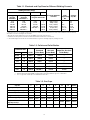
Table 1-1. Electrode and Cup Sizes for Different Welding Currents
Table 1-3. Gas Cups
Welding Currents (Amps)
Electrode Diameter
in Inches
High-
Impact Cup
No.
Ceramic
Cup No.
ACHF* DCSP** DCRP**
Using pure
tungsten
electrodes
Using
thoriated
electrodes ***
Using pure or thoriated
tungsten electrodes
5-15
10-60
50-100
100-150
150-210
200-275
5-20
15-80
70-150
140-235
225-325****
300-400****
5-20
15-80
70-150
150-250
250-400****
---
---
---
10-20
15-30
25-40
40-55
.020 (0.5 mm)
.040(1.0 mm)
1/16 (1.6 mm)
3/32 (2.4 mm)
1/8 (3.2 mm)
5/32 (4.0 mm)
4
4-5
4-5-6
5-6-7-8
6-7-8-10
8-10-12
4-5
4-5
4-5-6
6-7-8
7-8-10
10-12
* Values based on use of unbalanced wave transformer. If a balanced wave transformer is used, reduce maximum values in table by
about 30% or use the next larger size electrode.
** Exceeds the current rating of the torch (except 948361 (12-1/2 ft) using gas lens).
*** Balled electrode tip ends can best be formed and maintained at these ac current levels.
**** Thoriated tungsten electrodes are recommended when a gas lens and high frequency starting are used.
Electrode Size
Collet
Standard
Collet Body
Gas Lens
Collet Body*
Large Dia. Gas Lens
Collet Body**in. mm
0.020 0.5 10N21 10N29 45V29 ---
0.040 1.0 10N22 10N30 45V24 ---
1/16 1.6 10N23 10N31 45V25 ---
3/32 2.4 10N24 10N32 45V26 45V64
1/8 3.2 10N25 10N28 45V27 995795
5/32 4.0 54N20 406488*** 45V28 45V63
* Collet body insulator (P/N 54N01) is required when using gas lens collet bodies.
** Collet body insulator (P/N 54N63) is required when using large diameter gas lens collet bodies.
*** Use of a gas lens collet body is recommended for this size.
Cup No. 4 5 6 7 8 10 12 Short*
High-Impact Cup
10N50 10N49 10N48 10N47 10N46 10N45 10N44 ---
Sleeved High-Impact Cup
10N56 10N55 10N54 10N53 10N52 10N51 --- ---
Ceramic Cup
105Z43 105Z42 105Z44 105Z45 08N78 08N79 08N80 ---
Long Ceramic Cup
12N03 105Z60 12N02 105Z61 --- --- --- ---
Gas Lens High-Impact Cup
54N18 54N17 54N16 54N15 54N14 --- --- 54N19
Large Dia. Gas Lens
High-impact Cup
--- --- --- --- --- 53N88 53N87 53N89
Gas Lens Ceramic Cup
54N35 54N34 54N33 54N32 54N31 --- --- 54N36
* Short cups serve essentially as insulators. The short cup cannot be used with high-frequency or with currents greater than 300 amperes.

7
2.1 Setup and Installation
A. Connect the regulator/flowmeter to a gas cylin-
der. Refer to the instructions supplied with the
regulator/flowmeter for details on attaching and
adjusting the regulator.
B. Connect one end of the gas hose (P/N 40V77 or
34V38) to the regulator outlet and the other end
to the torch cable adaptor (P/N 45V62). On
torches with separate power cables, connect the
torch gas hose directly to the regulator outlet or
add one of the extension hoses by connecting
the argon coupling (P/N 11N17) between the
torch hose and the extension hose.
C. Connect the power cable adaptor or lug to the
welding power source, either directly or through
a suitable length of welding cable fitted with lugs.
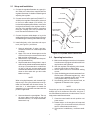
D. Install collet body, collet, electrode, and cup on
torch (see Figure 2-1) as follows:
1. Screw in collet body. (If using a gas lens,
assemble insulator on collet body before
installing.)
2. Apply a thin coat of silicone grease to the
surface of the cup that mates with the torch
body and then screw on cup.
3. Remove torch cap and slide collet into posi-
tion (tapered end first).
4. Slip electrode down through hole in top of
collet until end of electrode extends beyond
rim of cup. (Exact extension is variable from
as little as 1/8 inch for butt welding with
standard collet bodies to 3/4 inch or more for
corner or fillet welds with gas lens collet
bodies and cups.)
NOTE
When using high frequency with sleeved high-
impact cups, arcing may sometimes occur be-
tween the electrode and the steel sleeve. To
avoid this, it is advantageous to extend the
electrode as far as possible consistent with the
particular application.
5. Screw on the torch cap and tighten. The cap
will press down on the collet to grip the
electrode securely. To readjust electrode,
loosen torch cap.
Figure 2-1. Exploded View of HW-26 Torch
2.2 Operating Instructions
A. Make sure that all gas connections in the system
have been securely tightened and that the torch
cap has been well-tightened.
B. With the regulator flow-adjusting valve closed,
open the gas cylinder or station valve.
C. Set the power source for the desired welding
current.
D. Open all shielding gas valves downstream from
the flowmeter or flowmeter/regulator (e.g., valve
on torch, lever-operated shutoff valve, or sole-
noid-operated valve in power source.)
E. Set shielding gas flow to the desired level, as
registered on flowmeter tube or gauge.
NOTE
Purge the gas hose by allowing the gas to flow long
enough (up to 15 minutes on new torch; less than 5
minutes thereafter) to drive out air and moisture. This will
help prevent weld contamination.
F. Close the control switch at work position or at
power source.
G. Draw a test arc on a heavy piece of scrap steel
or copper. (Do not use a carbon block, which will
tend to contaminate the electrode.)
H. If the test arc is satisfactory, commence weld-
ing.
TORCH CAP
"O" RING
ELECTRODE
ELECTRODE COLLET
COLLET BODY
INSULATOR
GAS LENS
COLLET BODY
GAS LENS
CUP
TORCH BODY
COLLET BODY
CUP

8
3.1 Maintenance
If this equipment does not operate properly, stop work
immediately and investigate the cause of the malfunc-
tion. Maintenance work must be performed by an expe-
rienced person and electrical work by a trained electri-
cian. Do not permit untrained persons to inspect, clean,
or repair this equipment. use only recommended re-
placement parts.
A. A poor shielding gas connection, or a leaky
hose, will not only waste gas but permit the entry
of minute amounts of air, sufficient to contami-
nate both the electrode and the weld. Trouble
signs: a bluish cast on the electrode after it has
cooled; in welding aluminum, a dark gray de-
posit on or beside the weld bead.
B. If the argon valve leaks or operates improperly,
disassemble the valve as follows:
1. Unscrew the valve stem assembly (P/N
598279) until it clears the torch body.
2. Lift out and inspect the valve stem assem-
bly. If the stem or ball valve is damaged,
replace the entire assembly with a new one.
If the stem is in good condition, inspect the
two "O" rings. If they are worn, replace with
new ones.
NOTE
Prior to installing the new "O" ring, apply a
thin coat of silicone grease.
3. Reinstall the valve stem assembly, making
sure that the assembly is fully screwed into
the torch body so that the ball valve will seat
properly when the valve is in the closed
position.
C. Do not try to repair concentric power cable,
replace it. Two piece cable and hose assemblies
may be repaired using the repair kits noted in
parts breakdown. The kits include replacement
fittings and lug for the cable and hose.
D. If an electrode becomes contaminated, shut off
power, then remove electrode from torch. Break
off the contaminated end (nicking with a grinding
wheel first will help) and replace electrode.
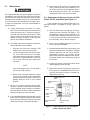
SCREEN (250 mesh)
54N66
INNER SPACER
54N68
OUTER SPACER
54N70
OUTER SNAPRING
54N71
INNER SNAP-
RING
54N69
SCREEN (100 mesh)
54N67
E. Keep an eye on the sealing "O" ring on the torch
cap. If it shows signs of wear or distortion, cut it
off. Then install new ring (P/N 98W18). Apply a
little silicone grease to the new ring before
attempting to slide it over the cap threads.
3.2 Replacement of Gas Lens Screens In P/Ns
45V63, 995795, and 45V64 (See Figure 3-1)
Large diameter gas lens collet bodies contain re-
placeable screens. If plugged by spatter, replace as
follows:
A. With the collet body removed from the torch,
remove the outer snapring (P/N 54N71). This
can be done by using a small screwdriver, or an
electrode with a diameter no greater than 3/32
in. Insert the tip in the slot on the outer sleeve of
the collet body, and pry out the snapring.
B. Using a pair of needle nose pliers, pry out the
inner snapring (P/N 54N69).
C. Hold the collet body with the screens down, and
gently tap the body on the work bench. The body
contains three fine and one coarse screens,
separated by spacers. If the screens are not
badly fouled, they should drop out of the body.
Excessive fouling may necessitate prying out
the screens.
D. Inspect the screens and replace those which
show plugging or other damage.
E. Replace the screens and spacers making sure
that a spacer is installed between each screen,
and that the coarsest screen is inserted last.
Replace the snaprings.
Figure 3-1. Replaceable Parts in Collet Bodies
45V63, 995795, and 45V64

9
4.1 REPLACEMENT PARTS
The following illustrations of the HW-26, HW-26R, and
HW-26F Torches identify each replacement part by
item number as tabulated in the related parts list. The
list identifies each part by part number, description, and
quantity used.
4.2 ORDERING
To assure proper operation, it is recommended that
only genuine ESAB parts and products be used with
this equipment. The use of non-ESAB parts may void
your warranty.
Replacement parts may be ordered from your ESAB
distributor or from:
ESAB Welding & Cutting Products
P.O. Box 100545
Ebenezer Road
Florence, SC 29501-0545
A. Give the part number, description and quantity
of each part required.
B. Give part number and description of equip-
ment on which the parts are to be used.
C. Indicate any special shipping instructions.
For technical assistance directly from an ESAB service
representative, call (843)664-4416. Additionally, ESAB
offers a toll free facsimile (FAX) service via 1-800-446-
5693.

10
10
9
8
7
6
1
4
5
3
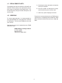
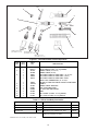
Figure 4-1. HW-26 Hard Body Torch Components
Gas Lens Access.
(See Tables 1-2, 1-3)
Standard Access.
(See Tables 1-2, 1-3)
LD Gas Lens Access.
(See Tables 1-2, 1-3)
2
5/8" - 18RH
Table 4-1. HW-26 Hard Body Assemblies
HW-26, 12-1/2 ft 17137 HW-26-2, (2) pc cable & hose, 12-1/2 ft 33857
HW-26, 25 ft 46V29 HW-26-2, (2) pc cable & hose, 25 ft 948127
HW-26V, 12-1/2 ft 17138 HW-26V-2, (2) pc cable & hose, 12-1/2 ft 33858
HW-26V, 25 ft 46V27 HW-26V-2, (2) pc cable & hose, 25 ft 948128
HW-26V-2-TL, (2) pc cable & hose with
twist-lock connector, 12 1/2-ft
35858
l Added new torch asembly, “M” edition, 3/96.
ITEM
NO.
QTY
REQ.
PART
NO.
DESCRIPTION
1
2
3
4
5
6
7
8
9
10
1
1
1
1
1
1
1
1
1
1
1
1
1
1
1
598478
598279
46V28
46V30
33697
33698
35874
34652
10N15A
45V
62
54N01
54N63
45V65
57Y04
57Y02
BODY W/ VALVE (includes valve stem 598279)
VALVE STEM (includes "O" ring 598869)
POWER CABLE (12-1/2 FT)
POWER CABLE (25 FT)
TWO PIECE CABLE & HOSE ASSY. (12-1/2 FT)
TWO PIECE CABLE & HOSE ASSY. (25 FT)
TWO PIECE CABLE & HOSE ASSY. WITH
TWIST-LOCK CONNECTOR (12 1/2 FT)
REPAIR KIT FOR TWO PIECE CABLE & HOSE ASSY.
HANDLE
POWER CABLE ADAPTER
GAS LENS INSULATOR
LD. GAS LENS INSULATOR
BODY
CAP, SHORT (includes "O" ring 98W18)
CAP, LONG (includes "O" ring 98W18)
l
l

11
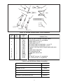
Table 4-2. HW-26R Silicone Rubber Assemblies
11
HW-26R, 12-1/2 ft 17137R
HW-26R, 25 ft 46V29R
HW-26RV, 12-1/2 ft 17138R
HW-26RV, 25 ft 46V27R
HW-26R-2, (2) pc cable & hose, 25 ft 948127R
HW-26RV-2, (2) pc cable & hose, 25 ft 948128R
10
9
8
7
6
Lg. Dia. Gas Lens
Access. (See Tables
1-2, 1-3)
Gas Lens Access.
(See Tables 1-2, 1-3)
Standard Access.
(See Tables 1-2, 1-3)
5
4
3
1
2
ITEM
NO.
QTY
REQ.
PART
NO.
DESCRIPTION
1
2
3
4
5
6
7
8
9
10
11
1
1
1
1
1
1
1
1
1
1
1
1
1
1
1
598478R
19622
46V28
46V30
33697
33698
34652
19624
45V62
54N01
54N63
19626
45V65R
57Y04
57Y02
BODY, W/ VALVE (includes valve stem 19622)
VALVE STEM (includes "O’ ring 598869)
POWER CABLE (12-1/2 FT)
POWER CABLE (25 FT)
TWO PIECE CABLE & HOSE ASSY. (12-1/2 FT)
TWO PIECE CABLE & HOSE ASSY. (25 FT)
REPAIR KIT FOR TWO PIECE CABLE AND HOSE ASSY.
HANDLE
POWER CABLE ADAPTER
GAS LENS INSULATOR
LD GAS LENS INSULATOR
GASKET
BODY
CAP, SHORT (includes "O" ring 98W18)
CAP, LONG (includes "O" ring 98W18)
Figure 4-2. HW-26R Silicone Rubber Torch Components
5/8" - 18RH

4
11
10
9
8
7
3
1
5
Gas Lens Access.
(See Tables 1-2, 1-3)
Standard Access.
(See Tables 1-2,
1-3)
Lg. Dia. Gas Lens
Access. (See Tables
1-2, 1-3)
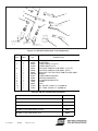
Figure 4-3. HW-26F Flexible Head Torch Components
ITEM
NO.
QTY
REQ.
PART
NO.
DESCRIPTION
1
2
3
4
5
6
7
8
9
10
11
1
1
1
1
1
1
1
1
1
1
1
1
1
1
1
34013
34074
46V28
46V30
33697
33698
34652
10N15A
45V62
54N01
54N63
19626
34014
57Y04
57Y02
BODY, W/ VALVE (includes valve stem 34074)
VALVE STEM
POWER CABLE (12-1/2 FT)
POWER CABLE (25 FT)
TWO PIECE CABLE & HOSE ASSY. (12-1/2 FT)
TWO PIECE CABLE & HOSE ASSY. (25 FT)
REPAIR KIT FOR TWO PIECE CABLE & HOSE ASSY.
HANDLE
POWER CABLE ADAPTER
GAS LENS INSULATOR
LD GAS LENS INSULATOR
GASKET
BODY
CAP, SHORT (includes "O" ring 98W18)
CAP, LONG (includes "O" ring 98W18)
F-11-262-M 05/2003 Printed in U.S.A.
HW-26F, 12-1/2 ft 33848
HW-26F, 25 ft 33849
HW-26FV, 12-1/2 ft 33850
HW-26FV, 25 ft 33851
HW-26FV-2, (2) pc cable & hose, 12-1/2 ft 33852
HW-26FV-2, (2) pc cable & hose, 25 ft 33853
Table 4-3. HW-26F Flexible Head Assemblies
6
2
5/8" - 18RH
-
 1
1
-
 2
2
-
 3
3
-
 4
4
-
 5
5
-
 6
6
-
 7
7
-
 8
8
-
 9
9
-
 10
10
-
 11
11
-
 12
12


ESAB GENUINE Heliarc HW-26 User manual
- Category
- Welding System
- Type
- User manual
- This manual is also suitable for
Ask a question and I''ll find the answer in the document
Finding information in a document is now easier with AI
Related papers
-
ESAB & HW-26F Tig Welding Torches User manual
-
-
-
-
-
-
-
-
ESAB Heliarc HW-26 Tig Welding Torches Troubleshooting instruction
-
Other documents
-
Vulcan 63618 Quick start guide
-
Miller MF000000L Owner's manual
-
-
 SKB 3-4250 User manual
-
-
-
-
-
-
