Page is loading ...

Warranty Registration and Inquiry
For product warranty registration, TOTO U.S.A. Inc. recommends online warranty registration. Please visit
our web site http://www.totousa.com. If you have questions regarding warranty policy or coverage, please con-
tact TOTO U.S.A. Inc., Customer Service Department, 1155 Southern Road, Morrow, GA 30260
(888) 295-8134 or (678) 466-1300 when calling from outside of U.S.A.
Installation Manual
Manual de Instrucciones
Manuel D’Installation
CST442

2 3
ENGLISH
ENGLISH
TABLE OF CONTENTS
THANKS FOR CHOOSING TOTO!
The mission of TOTO is to provide the world with healthy, hygienic and more
comfortable lifestyles. We design every product with the balance of form and
function as a guiding principle. Congratulations on your choice.
Thanks for Choosing TOTO! .................2
Common Tools Needed .........................2
Before Installation ................................... 2
Included Parts .........................................3
Care and Cleaning .................................. 3
Installation Procedure ............................4
Maintenance Instructions ....................... 8
Warranty ................................................10
Rough-In Dimensions ..........................29
COMMON TOOLS NEEDED
• 12” pipe wrench
• 10” adjustable wrench
• Carpenter’s Level
• Tape Measure
• Plier
MATERIALS REQUIRED:
• Flexible Supply Tube / Connector
• Supply Stop Valve
• Screwdriver
• Putty Knife
• Drill
•
11
/
64
” drill bit for wood floor installation
•
5
/
16
” drill bit for concrete/tile installation
• Mounting (T) Bolts & Nuts (2pc)
• Wax Ring / Seal
BEFORE INSTALLATION
Read instruction manual before installation.
Maintenance and warranty information included in manual, DO NOT DISCARD.
Locate water supply and drain pipe.
Verify enough space is available for installation and
unobstructed operation of equipment
(doors opening/closing, etc…). Failure to do this
beforehand may result in incorrect product installation
and possible malfunction.
Thoroughly flush the supply pipes of dirt and debris.
Proceed to install the supply hose to the tank and
make sure you do not damage the end connection of
the hose.
After installation, verify water and electricity are
working properly.
Gaps between the discharge pipe and the floor
should be filled with mold-resistant silicone-based
seal material (Mediseal).
Minimum required water pressure (flowing): 7 PSI at
2.64 Gal/min (0.05 MPa at 10 L/min). Maximum water
pressure (static): 108 PSI (0.75 MPa).
IMPORTANT!
For back-to-back installations, Tornado flushing systems require a WYE fitting
incorporated into the toilet drain system. Please contact your builer/contractor for
additional information prior to installation.
Double Combination WYE / 1/8 Bend
YES
Double Sanitary Tee / Sanitary Cross
NO

2 3
ENGLISH
ENGLISH
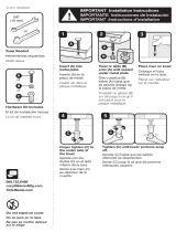
Please verify that all of the parts are included in the package:
INCLUDED PARTS AND INSTALLATION DIAGRAM
Mounting Screw with Washer
(2 pieces)
Anchor
(2 pieces)
Unifit Rough-In
Manual
WARNING!
DO NOT USE IN-TANK BOWL CLEANERS.
The use of high concentration of chlorine or chlorine-related products can seriously
damage fittings in the tank. This damage can cause leakage and serious property
damage. TOTO shall not be responsible or liable for any tank fitting failure or damage
caused by the use of in-tank bowl cleaners.
CARE AND CLEANING
Box 1
Rough-In Instructions
Template
x2
Tank to Bowl
Gasket
x4
x2
x4
Box 2

4 5
ENGLISH
ENGLISH
INSTALLATION PROCEDURE
Ill. 1
Ill. 3
NOTICE
NOTICE
A
A
A
A
1. Open the Unifit Rough-In packaging. Follow
the Unifit Rough-In Installation instruction.
2. Place the template into position and follow
its instructions to prepare for installing the
toilet bowl.
Do not move the Unifit Rough-In
on the Floor Flange after wax
seal is set. If this notice is disre-
garded, discard the wax ring and
replace with new wax ring.
3. Place the toilet bowl over the Unifit
Rough-In and align the holes on the
side of the toilet to the lines marked
“A” on the floor.
Insert the toilet bowl all the way
into position. If this notice is dis-
regarded, leakage may result.
Ill. 2
A
A

4 5
ENGLISH
ENGLISH
Ill. 4
Ill. 5
Ill. 6
INSTALLATION PROCEDURE
A
Tank to Bowl
Gasket
1
3
2
Fill
Valve Nut
Flush Valve Nut
Points of Contact
4. Align the toilet perpendicular to the
back wall and parallel to side walls; it
should not sit crooked or diagonal
(see illustration 4).
5. Make sure it’s aligned before securing.
6. Install the side screws to the mounting
blocks. Cover the screw head with the
provided screw caps (see illustration 5).
NOTE: THREE POINTS OF CONTACT
The toilet bowl has three points of contact,
which will actually contact the bottom of
the toilet tank when properly installed. The
location of these points can be seen on the
bowl at the tank receiving area. The three
points are front left (1), front right (2), and
back center (3). Recall these three points
during the Toilet Tank installation.
7. Place the tank upside down onto some pad-
ding. Inspect the smaller fill valve nut and
larger flush valve nut for a secure connection
(see Illustration 6).
Try to tighten the nuts with your hands. If loose,
tighten the nut hand tight and an additional
1/4 turn for the smaller fill valve nut and an
additional 1/2 turn for the larger flush valve nut.
Place the tank-to-bowl gasket onto the flush
valve nut.
While pressing down, spread the gasket over
the nut until the gasket touches the bottom of
the tank. A slight gap between the tank bot-
tom and the gasket is allowable.
A

6 7
ENGLISH
ENGLISH
INSTALLATION PROCEDURE
Metal Washer
Nut
Rubber Washer
Bolt
Cut Away View
NO
NO
YES
3
1 & 2
3 Gap
1 & 2
3
1 & 2
Gap
7/8” Ballcock Thread
HAND TIGHTEN ONLY
8. Lay the tank down on its back. Place a rubber
washer onto a brass bolt (see Illustration 7).
Reach inside the tank and position the bolt
through one of the holes in the bottom of the
tank. On the outside of the tank, place a metal
washer and nut onto the bolt. Hold the bolt
centered in the hole and tighten the nut finger
tight. Turn the nut an additional 1/2 turn with a
wrench. Repeat this process for the remaining
hole in the tank.
Pick up the tank and carefully guide the
brass bolts to align the tank with the bowl.
Attach a metal washer and the long nut to
each bolt. Tighten the nuts finger tight and
inspect that the tank is level (see Illustra-
tion 8).
Once level, tighten the bolts equally until
the tank makes THREE POINTS
OF CONTACT with the bowl.
9. Flush the water supply line for a few sec-
onds to remove any debris that may enter
the new fill valve. (For new home construc-
tions and/or additions, flush the water
supply line for more than a minute to help
remove any residual PVC adhesives, solder
flux, and/ or pipe sealants that were used
for the new plumbing.)
Connect the water supply line to the fill valve threads as
seen at the bottom of toilet tank (see Illustration 9). Tighten
this connection finger tight.
CAUTION: Avoid using a wrench to tighten the connection
as you may damage the plastic threads and/or cause the fill
valve to rotate inside the tank.
NOTE: The water supply pressure should be 20 to 80 psi
static.
Ill. 7
Ill. 8
Ill. 9

6 7
ENGLISH
ENGLISH
INSTALLATION PROCEDURE
Standard Seat
Connection
Washlet™ Seat
Connection
Silicon sealant
Toilet bowl
inner surface
Toilet bowl
outer surface
10. No ballcock / fill valve adjustments are
needed. The water will automatically stop
at proper level. Flush the toilet several
times. Check the valve for proper opera-
tion. Make sure that chain is not tangled
and that the flapper arm is in its proper
position.
11. Install the toilet tank lid onto the toilet
tank top.
12. When installing the washlet main unit
or standard toilet seat main unit, fol-
low the instructions on the Installation
Guide.
13. Once the installation is completed, pro-
ceed to verify the toilet unit for leaks.

8 9
ENGLISH
ENGLISH
MAINTENANCE INSTRUCTIONS
Fill Valve Replacement Procedure
1. Shut off the water supply to the toilet.
2. Flush toilet and remove remaining water from tank with a sponge.
3. Remove the water supply connection at the fill valve.
4. Remove old fill valve and use damp sponge to clean inside tank.
5. Place new fill valve inside tank.
6. Thread mounting nut onto fill valve shank and tighten the nut.
NO TE: Do not over-tighten. Be sure to install fill valve in a position that does not interfere
with the trip lever operation.
7. Connect water supply to fill valve shank and hand-tighten only.
NO TE: Do not overtighten. These are plastic parts. Never use pipe dope on any water
supply connection.
8. Attach refill tube to fill valve nipple and clip other end of refill tube to the overflow
pipe.
9. Turn water supply ON and check for leaks outside the tank.
NO TE: As water fills the tank, water is also directed into the overflow tube via the refill
tube. This additional flow of water is critical to refilling your toilet’s bowl. Once the
water stops filling the tank, some residual drops of water may drip from the fill
valve. This is NORMAL as these drops will subside.
Refer to the water level line stamp inside the tank.
1. The water level adjustment is located in the top
end of the fill valve. Use a flathead screwdriver to
make adjustments:
• To raise the water level: turn the screwdriver
clockwise, or towards the ‘+’ indicator.
• To lower the water level: turn the screwdriver
counter-clockwise, or towards the ‘-’ indicator.
2. Flush after each adjustment to check the water
level. When satisfied with the water level, flush
once more to verify.
ADJUSTING THE WATER LEVEL
Ill. 1
water level adjuster

8 9
ENGLISH
ENGLISH
1
2
1
2
3
1. Snap off the top cover by pulling from under the tab (see illustration 1).
2. Pinch the tabs of the lever arm to allow its removal (see illustration 2).
3. Snap off the adjustable rod from the bracket (1) allowing the unit to slide to the
bottom and remove the retainer tab by pulling as the arrow indicates (3)
(see illustration 3) .
4. Grab hold of the valve unit, twist 1/4 turn counterclockwise and pull the unit out
(see illustration 4).
5. Unscrew nut of the diaphragm housing (see illustration 5).
6. Remove the diaphragm from its housing by carefully pulling the edge of the
diaphragm (see illustration 6). Note the position of the diaphragm while removing.
7. Remove the strainer from the tube with needle nose pliers (see illustration 7). Use
twisting motion while pulling to help with removal.
8. Rinse all parts under running water to clear any debris, residues or films. Reinstall
all parts in reverse order. Turn the water ON and check for leaks and operation.
Ill. 1 Ill. 2 Ill. 3
Ill. 6
SERVICING THE FILL VALVE
Ill. 4
Ill. 5
NOTE: Due to water conditions in your area, the strainer may require periodic
cleaning. An indication that the strainer requires service can be seen in a delayed
fill cycle, intermittent fill cycle, or inadequate amount of water flow from the refill
tube.
1
2
Ill. 7

10 11
ENGLISH
ENGLISH
WARRANTY
1. TOTO warrants its vitreous china products (“Product”) to be free from defects in materials and work-
manship during normal use when properly installed and serviced, for a period of one (1) year from date
of purchase. This limited warranty is extended only to the ORIGINAL PURCHASER of the Product and
is not transferable to any third party, including but not limited to any subsequent purchaser or owner
of the Product. This warranty applies only to TOTO Product purchased and installed in North, Central
and South America.
2. TOTO’s obligations under this warranty are limited to repair, replacement or other appropriate adjust-
ment, at TOTO’s option, of the Product or parts found to be defective in normal use, provided that
such Product was properly installed, used and serviced in accordance with instructions. TOTO reserves
the right to make such inspections as may be necessary in order to determine the cause of the defect.
TOTO will not charge for labor or parts in connection with warranty repairs or replacements. TOTO is
not responsible for the cost of removal, return and/or reinstallation of the Product.
3. This warranty does not apply to the following items:
a. Damage or loss sustained in a natural calamity such as fire, earthquake, flood, thunder, electrical
storm, etc.
b. Damage or loss resulting from any accident, unreasonable use, misuse, abuse, negligence, or
improper care, cleaning, or maintenance of the Product.
c. Damage or loss resulting from sediments or foreign matter contained in a water system.
d. Damage or loss resulting from improper installation or from installation of the Product in a harsh
and/or hazardous environment, or improper removal, repair or modification of the Product.
(NOTE: Product model codes allow a maximum of 80 PSI. Check local codes or standards for
requirements).
e. Damage or loss resulting from electrical surges or lightning strikes or other acts which are not
the fault of TOTO or which the Product is not specified to tolerate.
f. Damage or loss resulting from normal and customary wear and tear, such as gloss reduction,
scratching or fading over time due to use, cleaning practices or water or atmospheric condi-
tions.
g. Tank flushing mechanisms of plastic or rubber moving parts.
h. Toilet seats of plastic, wood or metal.
4. In order for this limited warranty to be valid, proof of purchase is required. TOTO encourages war-
ranty registration upon purchase to create a record of Product ownership at http://www.totousa.com.
Product registration is completely voluntary and failure to register will not diminish your limited war-
ranty rights.
5. THIS WARRANTY GIVES YOU SPECIFIC LEGAL RIGHTS. YOU MAY HAVE OTHER RIGHTS WHICH
VARY FROM STATE TO STATE, PROVINCE TO PROVINCE OR COUNTRY TO COUNTRY.
6. To obtain warranty repair service under this warranty, you must take the Product or deliver it prepaid
to a TOTO service facility together with proof of purchase (original sales receipt) and a letter stating
the problem, or contact a TOTO distributor or products service contractor, or write directly to TOTO
U.S.A., INC., 1155 Southern Road, Morrow, GA 30260 (678) 466-1300 or (888) 295-8134, if outside the
U.S.A. If, because of the size of the Product or nature of the defect, the Product cannot be returned
to TOTO, receipt by TOTO of written notice of the defect together with proof of purchase (original
sales receipt) shall constitute delivery. In such case, TOTO may choose to repair the Product at the
purchaser’s location or pay to transport the Product to a service facility.
WARNING! TOTO shall not be responsible or liable for any failure of, or damage to, this Product caused
by either chloramines in the treatment of public water supply or cleaners containing chlorine (calcium
hypochlorite). NOTE: The use of a high concentrate chlorine or chlorine related products can seriously
damage the fittings. This damage can cause leakage and serious property damage.
THIS WRITTEN WARRANTY IS THE ONLY WARRANTY MADE BY TOTO. REPAIR, REPLACEMENT OR
OTHER APPROPRIATE ADJUSTMENT AS PROVIDED UNDER THIS WARRANTY SHALL BE THE EXCLU-
SIVE REMEDY AVAILABLE TO THE ORIGINAL PURCHASER. TOTO SHALL NOT BE RESPONSIBLE FOR
LOSS OF THE PRODUCT OR FOR OTHER INCIDENTAL, SPECIAL OR CONSEQUENTIAL DAMAGES OR
EXPENSES INCURRED BY THE ORIGINAL PURCHASER, OR FOR LABOR OR OTHER COSTS DUE TO
INSTALLATION OR REMOVAL, OR COSTS OF REPAIRS BY OTHERS, OR FOR ANY OTHER EXPENSE
NOT SPECIFICALLY STATED ABOVE. IN NO EVENT WILL TOTO’S RESPONSIBILITY EXCEED THE PUR-
CHASE PRICE OF THE PRODUCT. EXCEPT TO THE EXTENT PROHIBITED BY APPLICABLE LAW, ANY
IMPLIED WARRANTIES, INCLUDING THAT OF MERCHANTABILITY OR FITNESS FOR USE OR FOR A
PARTICULAR PURPOSE, ARE EXPRESSLY DISCLAIMED. SOME STATES DO NOT ALLOW LIMITATIONS
ON HOW LONG AN IMPLIED WARRANTY LASTS, OR THE EXCLUSION OR LIMITATION OF INCIDEN-
TAL OR CONSEQUENTIAL DAMAGES, SO THE ABOVE LIMITATION AND EXCLUSION MAY NOT APPLY
TO YOU.

10 11
ENGLISH
ENGLISH
NOTES

12
ESPAÑOL
ÍNDICE
¡GRACIAS POR ELEGIR TOTO!
La misión de TOTO es brindarle al mundo estilos de vida sanos, higiénicos y
más cómodos. Diseñamos cada producto con el balance de forma y función
como un principio rector. Felicidades por su elección.
¡Gracias por elegir TOTO!...................12
Herramientas comunes necesarias .....12
Antes de la instalación .........................12
Partes incluidas .....................................13
Cuidado y limpieza ...............................13
Procedimiento de instalación ..............14
Mantenimiento .....................................19
Garantía .................................................20
Bosquejo ...............................................31
HERRAMIENTAS COMUNES NECESARIAS
• 12” llave de tubo
• 10” llave ajustable
• Nivel de carpintero
• Cinta métrica
• Alicate
MATERIALES NECESARIOS:
• Tubo / conector de suministro flexible
• Válvula de retención de suministro
•
11
/
64
” broca para instalación en piso de madera
•
5
/
16
” broca para instalación de concreto/azulejo
• Destornillador
• Espátula
• Taladro
• Pernos (T) de montaje & tuercas (2pc)
• Anillo de cera / sello
ANTES DE LA INSTALACIÓN
Lea el manual de instrucciones antes de la instalación.
En el manual se incluye información sobre el mantenimiento y la garantía;
NO LO DESECHE.
Localice el suministro de agua y la tubería de desagüe.
Verifique que haya espacio suficiente para la instalación y
para la libre operación del equipo (apertura/cierre de
puertas, etc.). El no hacerlo de antemano podría dar
lugar a una incorrecta instalación del producto y un
posible mal funcionamiento.
Limpie perfectamente las tuberías de suministro para
descargarlas de suciedad y residuos. Proceda a instalar
la manguera de suministro en el tanque y asegúrese
de no dañar el extremo de la misma.
Luego de la instalación, verifique que el agua y la
electricidad estén funcionando correctamente.
Se deben rellenar las brechas entre la tubería de
descarga y el suelo con un material de sellado a base
de silicona y resistente al moho (Mediseal).
Presión mínima del agua requerida (flujo): 7PSI a
2,64gal/min (0,05MPa a 10L/min). Presión máxima del
agua (estática): 108PSI (0,75MPa).
¡IMPORTANTE! Para instalaciones consecutivas, los sistemas de descarga Tornado
requieren la incorporación de un accesorio WYE en el sistema de desagüe del inodoro.
Contáctese con su constructor/contratista para obtener información adicional antes de
la instalación.
WYE de doble combinación/
curva de 1/8
SI
Conexión sanitaria en “T” doble/
conexión sanitaria en cruz
NO

13
ESPAÑOL
Verifique que todas las piezas estén incluidas en el envase:
DIAGRAMA DE INSTALACIÓN Y PARTES INCLUIDAS
Tornillo de montaje con
Arandela (2piezas)
Anclaje
(2piezas)
Conexión de salida de PVC
Manual
¡ADVERTENCIA!
NO UTILICE LIMPIADORES DENTRO DE LA TAZA DEL TANQUE.
El uso de productos clorados o con alta concentración de cloro puede dañar gravemente
los accesorios en el tanque. Estos daños pueden causar fugas y averías graves de mate-
riales.
TOTO no será responsable de la mala colocación del tanque ni de los daños causados
por el uso de limpiadores en la taza del tanque.
CUIDADO Y LIMPIEZA
Instrucciones de montaje
Plantilla
x2
Junta de Tanque
a Recipiente
x4
x2
x4
Caja 1
Caja 2

14
ESPAÑOL
PROCEDIMIENTO DE INSTALACIÓN
Ill. 1
AVISO
AVISO
A
A
Ill. 3
A
A
Ill. 2
A
A
1. Abra el embalaje del montaje Unifit.
Siga las instrucciones de instalación del
montaje Unifit.
2. Coloque la plantilla en posición y siga sus
instrucciones para preparar la instalación
de la taza del inodoro.
No mueva el montaje Unifit
sobre la brida del suelo
después de colocado el
sello de cera. Si ignora este
aviso, deseche el anillo de
cera y reemplácelo por uno
nuevo.
3. Coloque la taza del inodoro sobre el
montaje Unifit y alinee los agujeros
al costado del inodoro con las líneas
“A” marcadas en el suelo.
Coloque el inodoro en la
posición correcta final. Si
ignora este aviso, podría
derivar en una filtración.

15
ESPAÑOL
PROCEDIMIENTO DE INSTALACIÓN
Empaquetadura
tanque-recipiente
1
3
2
Tuerca Valvula
de Llenado
Tuerca Valvula
de Vaciado
Puntos de Contacto
Ill. 4
Ill. 5
Ill. 6
A
A
4. Alinee el inodoro en forma perpendicular
a la pared trasera y paralelo a las paredes
laterales; no debe estar inclinado ni en
diagonal (ver Ilustración4).
5. Asegúrese de que esté alineado antes de
fijarlo.
6. Instale los tornillos laterales en los blo-
ques de montaje. Cubra la cabeza de los
tornillos con los tapones provistos (ver
Ilustración5)
NOTA: TRES PUNTOS DE CONTACTO
El recipiente del inodoro tiene tres puntos
de contacto, los cuales deberán tocar la
parte de abajo del tanque cuando se es
instalado debidamente. La ubicación de
estos puntos puede ser vista en la parte
del recipiente donde debe ir el tanque.
Los tres puntos son delantero izquierdo
(1), delantero derecho (2), y tracero central
(3). Recuerde estos tres puntos cuando
esté instalando el tanque. en la parte del
recipiente donde debe ir el tanque.
7. Dé vuelta al inodoro de modo que
quede mirando hacia abajo sobre algún
acol chonado. Inspeccione la tuerca
pequeña de la válvula de llenado y la
tuerca grande de la válvula de vaciado
para garantizar la conexión (ver Ilus-
tración 6). Trate de apretar las tuercas
con su mano. Si aún siguen holgadas,
apriételas manualmente y dé 1/4 de vuel-
ta adicional a la tuerca pequeña de la
válvula de llenado y 1/2 vuelta a la tuerca
grande de la válvula de vaciado.
Coloque la empaquetadura del tanque-
recipiente sobre la tuerca de la válvula
de vaciado. Mientras presiona hacia
abajo, despliegue la empaquetadura
sobre la tuerca hasta que esta toque el
fondo del tanque. Un pequeño espacio
entre el fondo del tanque y la empaqu-
etadura está permitido.

16
ESPAÑOL
PROCEDIMIENTO DE INSTALACIÓN
NO
NO
SI
Rondana
Metalica
Tuerca
Rondana de
Goma
Perno
Vista en Corte
3
1 & 2
3 Es-
pacio
1 & 2
3
1 & 2
Espacio
Ill. 7
Ill. 8
Ill. 9
Rosca de Llave de Bola-22.2mm
SOLO APRETAR MANUAL
8. Acueste el tanque sobre su parte trasera.
Coloque una rondana de goma en el perno
metálico (ver Ilustración 7).
Extienda su mano dentro del tanque y colo-
que el perno a través de uno de los orificios
del fondo del tanque. En la parte de afuera
del tanque, coloque una rondana metálica y
una tuerca en el perno. Mantenga el perno
centrado en el orificio y apriete la turca con
sus dedos. Dé 1/2 vuelta adicional a la tuerca
con la llave para tubería. Repita este proceso
para el otro orificio del tanque.
Levante el tanque y cuidadosamente guíe los
pernos metálicos para alinear el tanque con
el recipiente. Fije una rondana metálica y una
tuerca a cada perno. Apriete las tuercas con
sus dedos e inspeccione que el tanque haya
quedado nivelado (ver Ilustración 8). Una
vez nivelado, apriete los pernos igualmente
hasta que el tanque haga TRES PUNTOS DE
CONTACTO con el recipiente.
9. Descargue la línea de suministro de agua por
algunos segundos para remover cualquier
suciedad que haya entrado a la nueva vávula
de llenado. (Para construcciones nuevas y/o
adiciones, descargue la línea de suministro de
agua por más de 1 minuto para ayudar a re-
mover cualquier residuo de adhesivo de PVC,
soldadura plástica, y/o sellantes de tubería
que fueron usados para la nueva tubería).
Conecte la línea de suministro de agua a la
rosca de la válvula de llenado como se ve en
la parte de abajo del tanque del inodoro (ver
Ilustración 9). Apriete esta conexión con sus
dedos.
PRECAUCIÓN: Evite usar una llave para tu-
bería al apretar la tubería ya que esto podría
dañar las roscas plásticas y/o causar que la
válvula de llenado rote dentro del tanque.
NOTA: La presion de la línea de suministro de
agua debe ser de 20 a 80 psi estática.

17
ESPAÑOL
10. No es necesario ajustar la válvula de
relleno/ llave del flotador. El agua se
tendrá al nivel apropiado de forma au-
tomática. Tire la cadena varias veces.
Controle que la válvula de la cisterna
funcione adecuadamente. Asegúrese
de que la cadena no esté enredada y
que el brazo de la cisterna se encuen-
tre en la posición correcta.
11. Instale la tapa del tanque en el in-
odoro.
12. Cuando instale la unidad principal
Washlet o la unidad principal del
asiento para inodoro estándar, siga las
instrucciones de la Guía de Instalación.
13. Una vez que haya completado la
instalación, verifique que la unidad del
inodoro no tenga filtraciones.
Conexión del
asiento estándar
Conexión del
asiento Washlet™
Sellador de silicona
Superficie interna de la
taza del inodoro
Superficie externa de la
taza del inodoro
PROCEDIMIENTO DE INSTALACIÓN

18
ESPAÑOL
REEMPLAZO LA VÁLVULA DE LLENADO
AJUSTE DEL NIVEL DEL AGUA
Ill. 1
Consulte la marca que indica el nivel de agua dentro del
tanque.
1. El ajuste del nivel del agua se encuentra en el
extremo superior de la válvula de llenado. Use un
destornillador plano para realizar ajustes:
• Para elevar el nivel del agua: gire el
destornillador en el sentido de las agujas del
reloj o hacia el indicador ‘+’.
• Para bajar el nivel del agua: gire el
destornillador en el sentido contrario a las
agujas del reloj o hacia el indicador ‘-’.
2. Descarge el inodoro déspues de cada ajuste vérifier
el nivel de agua. Cuando esté satisfecho con el
nivel del agua, vuelva a descargar el inodoro para
verificarlo.
ajustador de
palanca de agua
1. Cierre el suministro de agua al excusado.
2. Tire la cadena y retire el agua restante del tanque con una esponja.
3. Quite la conexión del suministro de agua de la válvula de llenado.
4. Quite la válvula de llenado anterior y utilice la esponja húmeda para limpiar el orificio
del tanque.
5. Coloque la válvula de llenado nueva en el orificio del tanque.
6. Enrosque la tuerca de montaje en el vástago de la válvula de llnado y ajuste la tuerca.
NO TA: No ajuste demasiado. Asegúrese de instalar la válvula de llenado en una
posición que no interfiera con el funcionamiento de la palanca de descarga.
7. Conecte el suministro de agua al vástago de la válvula de llenado y sólo ajústelo
manualmente.
NO TA: No ajuste demasiado. Éstas son piezas plásticas. No utilice lubricante en nin
guna conexión de suministro de agua.
8. Conecte el tubo de relleno al niple de la válvula y sujete el otro extremo del tubo de
relleno al tubo de desagüe.
9. Abra el suministro de agua y verifique que no haya pérdida de agua fuera del tanque.
NO TA: A medida que el agua llene el tanque, también será derivada al tubo de
desagüe a traves del tubo de relleno. Este flujo de agua adicional es funda
mental para rellenar el recipiente del excusado. Una vez que el tanque está
lleno y el suministro de agua se interrumpe, es probable que caigan algunas
gotas de agua residual de la válvula de llenado. Esto es NORMAL y las gotas
dejarán de caer.

19
ESPAÑOL
1
2
MANTENIMIENTO DE LA VÁLVULA DE LLENADO
1
2
1
2
3
1. Desprenda la cubierta superior tirando de debajo de la pestaña
(ver ilustración 1).
2. Presione las pestañas del brazo de palanca para permitir su extracción.
(ver ilustración 2).
3. Desprenda la barra ajustable del soporte (1) permitiendo que la unidad se deslice
hacia la parte inferior y retire la pestaña del retén tirando como indica la flecha (3)
(ver ilustración 3) .
4. Mientras sostiene la válvula con una mano, gire la tapa 1/4 de vuelta en sentido
contrario a las manecillas del reloj y retírela (ver ilustración 4).
5. Destornille la tuerca de la cubierta del diafragma (ver ilustración 5).
6. Retire la diafragma desde la cubierta tirando con cuidado del borde del diafragma
(ver ilustración 6). Tenga en cuenta la posición del diafragma mientras lo extrae.
7. Retire el colador desde el tubo con pinzas de punto (ver ilustración 7). Use el
movimiento giratorio mientras tira para ayudar con la extracción.
8. Enjuague todas las partes con agua corriente para eliminar cualquier residuo o
película. Vuelva a instalar todas las piezas en orden inverso. Abra el suministro de
agua y verifique si hay fugas y si funciona.
Il. 1 Il. 2 Il. 3
Il. 6
Il. 4
Il. 5
NOTA: Debido a las condiciones del agua en su área, el colador puede requerir una
limpieza periódica. Los indicadores de que el filtro requiere servicio incluyen un
ciclo de llenado retardado, ciclo de llenado intermitente o cantidad inadec
uada de flujo de agua del tubo de llenado.
Il. 7

20
ESPAÑOL
GARANTÍA
1. TOTO garantiza que su vitreos china producto no presenta defectos en sus materiales ni de fabricación durante
su uso normal cuando es instalado y mantenido adecuadamente, por un periodo de uno (1) año(s) a partir de
la fecha de compra. Esta garantía limitada es válida solamente para el COMPRADOR ORIGINAL del Producto
y no es transferible a una tercera persona, incluyendo, pero sin limitarse a, cualquier comprador o propietario
subsecuente del Producto. Esta garantía aplica solamente al Producto TOTO comprado e instalado en América
del Norte, Central, Latina y del Sur.
2. Las obligaciones de TOTO bajo esta garantía se limitan a la reparación, cambio o cualquier otro ajuste, a petición
de TOTO, del Producto o partes que resulten defectuosas en su uso normal, siempre que dicho Producto haya
sido instalado, utilizado y mantenido de acuerdo con las instrucciones. TOTO se reserve el derecho de hacer
tantas inspecciones como sean necesarias para determinar la causa del defecto. TOTO no cobrará por la mano
de obra o partes relacionadas con las reparaciones o cambios garantizados. TOTO no es responsable por el costo
de la remoción, devolución y/o reinstalación del Producto.
3. Esta garantía no aplica en los siguientes casos:
a) Daño o pérdida ocurrida en un desastre natural, tal como: incendio, sismo, inundación, relámpago, tor-
menta eléctrica, etc.
b) Daño o pérdida resultado de cualquier accidente, uso inaceptable, mal uso, abuso, negligencia o cuidado,
limpieza o mantenimiento inadecuado del Producto.
c) Daño o pérdida causada por los sedimentos o material extraña contenida en un sistema de agua.
d) Daño o pérdida causada por una mala instalación o por la instalación del Producto en un ambiente duro
y/o peligroso, o una remoción, reparación o modificación inadecuada del Producto. (NOTA: Los códigos
de modelo del producto permiten un máximo de 80 PSI. Revise los códigos locales o las normas de requi-
sitos.)
e) Daño o pérdida causada por sobrecargas eléctricas o rayos u otros actos que no sea responsabilidad de
TOTO o que el Producto no esté especificado para tolerar.
f) Daño o pérdida causada por el uso normal y personalizado, tal como reducción del brillo, rayado o pér-
dida de color en el tiempo debido al uso, prácticas de limpieza o condiciones del agua o atmosféricas.
4. Para que esta garantía limitada sea válida, prueba de compra es necesaria. TOTO anima el registro de la garantía
sobre compra para cree un archivo de la propiedad del producto en http://www.totousa.com. El registro del pro-
ducto es totalmente voluntario y la falta a registrar no disminuirá sus derechas de garantía limitada.
5. ESTA GARANTÍA LE DA DERECHOS LEGALES ESPECÍFICOS. USTED PODRÍATENER OTROS DERECHOS QUE
PUEDEN VARIAR DEPENDIENDO DEL ESTADO O PROVINCIA EN EL QUE SE ENCUENTRE.
6. Para obtener el servicio de reparación de esta garantía, debe llevar el Producto o enviarlo prepagado a un modulo
de servicios TOTO junto con la prueba de compra (recibo de compra original) y una carta en la que plantee el
problema, o póngase en contacto con un distribuidor TOTO o el contratista de servicio de los productos, o es-
criba directamente a TOTO U.S.A., INC., 1155 Southern Road, Morrow, GA 30260 (678) 466-1300 o 888) 295-8134,
si fuera de los E.E.U.U. Si, debido al tamaño del producto o naturaleza del defecto, el Producto no puede ser
devuelto a TOTO, la recepción en TOTO del aviso escrito del defecto junto con la prueba de compra (recibo de
compra original) constituirá el envío. En tal caso, TOTO podrá escoger entre reparar el Producto en el domicilio
del comprador o pagar el transporte del Producto a un módulo de servicio.
ESTA GARANTÍA ESCRITA ES LA ÚNICA GARANTÍA HECHA POR TOTO. LA REPARACIÓN, CAMBIO U OTRO
AJUSTE ADECUADO, TAL COMO APARECE EN ESTA GARANTÍA, SERÁ EL ÚNICO REMEDIO DISPONIBLE PARA
EL COMPRADOR ORIGINAL. TOTO NO SERÁ RESPONSABLE POR LA PÉRDIDA DEL PRODUCTO O POR CUAL-
QUIER OTRO DAÑO ACCIDENTAL, ESPECIAL O CONSECUENTE O POR DAÑOS INCURRIDOS POR EL COM-
PRADOR ORIGINAL, O POR LA MANO DE OBRA U OTROS COSTOS RELACIONADOS CON LA INSTALACIÓN O
REMOCIÓN, O COSTOS DE REPARACIONES HECHAS POR OTROS, O POR CUALQUIER OTRO GASTO NO IN-
DICADO DE MANERA ESPECÍFICA EN LOS PÁRRAFOS ANTERIORES. EN NINGÚN CASO LA RESPONSABILIDAD
DE TOTO EXCEDERÁ EL PRECIO DE COMPRA DEL PRODUCTO. EXCEPTO EN LA MEDIDA EN QUE QUEDE PRO-
HIBIDO POR LA LEYAPLICABLE, TODA GARANTÍA IMPLÍCITA, INCLUYENDO AQUELLAS DE COMERCIABILIDAD
O IDONEIDAD DE USO PARA EL USO O PARA UN PROPÓSITO PARTICULAR, ESTÁ EXPRESAMENTE PROHIBIDA.
ALGUNOS ESTADOS NO PERMITEN LAS LIMITACIONES ACERCA DE LA DURACIÓN DE UNA GARANTÍATÁCITA,
O LA EXCLUSIÓN O LIMITACIÓN DE DAÑOS INCIDENTALES O CONSECUENTES, POR LO QUE LA LIMITACIÓN
E INCLUSIÓN ANTERIORES PUEDEN NO APLICAR A USTED.
AVISO TOTO no será responsable de fallas o daños ocasionados en este producto de plomería o componente del
producto causados por cloraminas en el tratamiento del suministro de agua público o en los limpiadores en el recipi-
ente del tanque que contengan cloro (hipoclorito de calcio). Nota: el uso de cloro en alta concentración o productos
derivados del cloro puede dañar seriamente los accesorios. Este daño puede ocasionar fugas y daños graves en la
propiedad. Para obtener más información, llámenos al (888) 295-8134.
/