
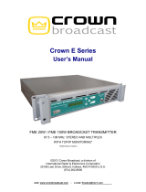
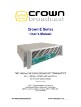
i
FM RTC
Redundant Transmitter Controller
User's Manual
©2001 Crown Broadcast, a division of International Radio and Electronics, Inc.
25166 Leer Drive, Elkhart, Indiana, 46514-5425 U.S.A.
(219) 262-8900
Redundant Transmitter Controller
RTC
Tx1AudioOn
Tx2AudioOn
Tx1Fault
Tx2Fault
HeartBeat
AntennaPos1
AntennaPos2
Shutdown
VOX
Attack
Timeout
VOX
Decay
Timeout
Operator
Restart
Tx1RF
Powe r
Threshold
Tx2RF
Powe r
Threshold
®

ii
Revision control
Revision Print date
Revision 3 September 2002
Important Notices
©2001, Crown Broadcast, a division of International Radio and Electronics, Inc.
All rights reserved. No part of this publication may be reproduced, transmitted,
transcribed, stored in a retrieval system, or translated into any language in any
form by any means without the written permission of Crown International, Inc.
Printed in U.S.A.
Crown attempts to provide information that is accurate, complete, and useful.
Should you find inadequacies in the text, please send your comments to the
following address:
International Radio and Electronics
25166 Leer Drive, P.O. Box 2000
Elkhart, Indiana, 46515-2000 U.S.A.

iii
ContentsContents
ContentsContents
Contents
Section 1-Getting Acquainted........................................... 1
The RTC System............................................................................................................1
Antenna Switch .............................................................................................................1
Transmitters...................................................................................................................2
RF Load (optional).........................................................................................................2
Safety Considerations....................................................................................................2
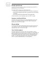
Dangers ................................................................................................................2
Warnings ..............................................................................................................2
Cautions................................................................................................................2
Front Panel Indicators....................................................................................................3
Heartbeat LED.......................................................................................................3
Tx1 and Tx2 Audio On ..........................................................................................3
Tx1 and Tx2 Faults................................................................................................4
Antenna Position 1 and 2......................................................................................4
Shutdown .............................................................................................................4
Front Panel Controls......................................................................................................5
System Reset........................................................................................................5
Operator Restart ...................................................................................................5
VOX Timeout Settings...........................................................................................5
Transmitter Power Threshold................................................................................6
Section 2—Installation .................................................. 7
Unpacking......................................................................................................................7
Operating location .........................................................................................................7
Power connections ........................................................................................................7
Mounting and connecting..............................................................................................7
RF Connections .............................................................................................................8
Section 3—Operation .................................................... 9
Start up sequence..........................................................................................................9
Presetting controls................................................................................................9
Power up ..............................................................................................................9
End of day operation......................................................................................................9
Section-4 Troubleshooting .............................................10
No heartbeat light, no operation, .................................................................................10
No Audio Signal Detected............................................................................................11
Excessive or insufficient VOX time ..............................................................................11
RF power settings........................................................................................................11
Tx1 or Tx2 fault locked out..........................................................................................11
Section 5—Service and Support ......................................12
Service.........................................................................................................................12
24–Hour Support.........................................................................................................12
Spare Parts..................................................................................................................12
Factory Service Instructions ........................................................................................14

iv
Notes

1
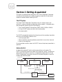
Section 1-Getting Acquainted
This section provides a general description of the Crown Redundant Transmitter
Controller and introduces you to safety conventions used within this document.
Review this material before installing the RTC.
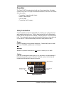
The RTC System
The Crown FM RTC Redundant Transmitter Control is a simple, easy to use
solution for creating redundant broadcast transmitter systems. A complete redun-
dant transmission system consists of the following:
• Two Crown Broadcast FM transmitters (FM30, FM100, FM250 or FM500)
• A Crown FM RTC system controller with interface cables
• An antenna switch
The FM RTC automatically switches from the primary to the secondary transmitter
when any of the following conditions occur
• Loss of program audio
• When transmitter power drops below a preset limit for more than 4 seconds
• A fault in the transmitter.
Once the problem condition clears, the FM RTC returns the primary transmitter to
operation.
Antenna Switch
An electrically operated RF switch switches transmitters in the system. The
FM RTC continuously monitors the state of the antenna RF switch. If the antenna
switch either fails to switch correctly or unexpectedly changes states, the Crown
FM RTC disables both transmitter carriers until the station engineer corrects the
problem and resets the system.
FM RTC
PrimaryFM
Transmitter
SecondaryFM
Transmitter
Antenna
Switch
Antenna
AC Power
Remote I/O Cable
RFSwitch Control
AuxI/O,RS-232
Relay Output, and 2
Opto-Isolated Inputs
Progam Audio
Remote I/O Cable
RF Coax Port 1 RF Coax Port 3
RF Coax Port 2

2
Redundant Transmitter Controller User’s Manual
Transmitters
The Crown FM RTC interfaces directly with two Crown transmitters. All signals
connect to the FM RTC through the transmitter Remote I/O connector on the back
of the transmitter.
• Transmitter Composite Audio Output
• Meter RF Watts Output
• Carrier Enable
• Transmitter Fault Summary
Severe shock hazard!
Turn power off and
wait approximately 1
minute for capacitors
to discharge before
handling them.
WARNING
Type of Hazard
Pictorial Indication
of Hazard
Explanation of
Hazard
Safety Considerations
Crown Broadcast assumes the responsibility for providing you a safe product and
safety guidelines during its use. “Safety” means protection to all individuals who
install, operate, and service the transmitter as well as protection of the transmitter
itself. To promote safety, we use standard hazard alert labeling on the product and
in this manual. Follow the associated guidelines to avoid potential hazard.
Dangers
DANGER represents the most severe hazard alert. Extreme bodily harm or death
will occur if DANGER guidelines are not followed.
Warnings
WARNING represents hazards which could result in severe injury or death.
Cautions
CAUTION indicates potential personal injury or equipment or property damage if
the associated guidelines are not followed. Particular cautions in this text also
indicate unauthorized radio-frequency operation.
Sample Hazard Alert

3
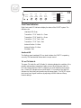
Tx1AudioOn
Tx2AudioOn
Tx1Fault
Tx2Fault
HeartBeat
AntennaPos1
AntennaPos2
Shutdown
VOX
Attack
Timeout
VOX
Decay
Timeout
Operator
Restart
Tx1RF
Power
Threshold
Tx2RF
Power
Threshold
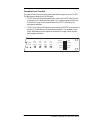
Front Panel Indicators
Eight front panel LED indicators display the status of the FM RTC system. The
indicators are
Heartbeat LED-Green
Transmitter 1 “Tx1” Audio On - Green
Transmitter 2 “Tx2” Audio On - Green
Transmitter 1 “Tx1” Fault - Red
Transmitter 1 “Tx2” Fault - Red
Antenna Position 1-Yellow
Antenna Position 2-Yellow
Shutdown -Red
Heartbeat LED
The flashing green heartbeat LED is a visual indicator the FM RTC is operating
correctly. The heartbeat led flashes about once per second.
Tx1 and Tx2 Audio On
The green Tx1 Audio On and Tx2 Audio On indicators display the condition of the
primary and secondary transmitter’s audio sources. When the green Audio On
LED’s are illuminated, the FM RTC is detecting an audio feed from the transmit-
ters. A dark LED indicates a loss of audio signal. It is normal for the Audio On
indicators to flash briefly as the audio sources change levels. The FM RTC rejects
short-term loss of signal conditions by adjusting the VOX Attack and Decay
timeout settings.

4
Redundant Transmitter Controller User’s Manual
Tx1 and Tx2 Faults
The red Tx1 and Tx2 Fault indicators illuminate for the following conditions:
• A fault in the indicated transmitter. The exact fault is indicated on the
transmitter’s front panel.
•The RF output power for the indicated transmitter is below the level set by the
FM RTC front panel threshold control.
When either of the fault conditions occur in the primary transmitter, the FM RTC
switches to the secondary transmitter. If the secondary transmitter develops a
fault while transmitting, the FM RTC shuts down both transmitters until either
transmitter’s fault condition clears.
Antenna Position 1 and 2
The yellow Antenna Position 1 and 2 indicators display the position of the antenna
switch. If the antenna switch is unable to change switch positions, takes too long
to change switch positions or unexpectedly switches positions, both the Antenna
Position indicators and the Shutdown indicator flash to indicated an antenna
switch fault. Press and release the System Reset button to clear an antenna
position fault and restore the FM RTC to normal operation.
Shutdown
The red Shutdown LED alerts the operator to one of the following problems:
•An antenna switch position error. An antenna switch error usually
requires operator intervention. Press and release the System Reset
button to clear an antenna position fault and restore the FM RTC to
normal operation.
• Both primary and secondary transmitters report a fault condition at the
same time. The FM RTC automatically recovers from a shutdown condi-
tion caused by a transmitter fault condition when either the primary or
secondary transmitter recovers and is able to resume operation.
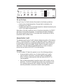
Tx1AudioOn
Tx2AudioOn
Tx1Fault
Tx2Fault
HeartBeat
AntennaPos1
AntennaPos2
Shutdown
VOX
Attack
Timeout
VOX
Decay
Timeout
Operator
Restart
Tx1RF
Power
Threshold
Tx2RF
Power
Threshold

5
Front Panel Controls
There are six front panel controls on the FM RTC. These controls are:
• Tx1 RF Power Threshold
• Tx2 RF Power Threshold
• VOX Attack Timeout
• VOX Decay Timeout
• System Reset
• Operator Restart
The following sections detail the operation and use of each of these controls.
System Reset
The System Reset is the only unlabeled control on the FM RTC front panel.
Fault conditions, such as antenna relay switching problems or transmitter lock-outs
require user intervention by resetting the RTC using this control.
Operator Restart
Operator Restart button has the following function on the FM RTC.
• Pushing and releasing Operator Restart switches the system between the
primary and secondary transmitters. Switch between transmitters to
exercise the RF antenna relay or verify the operation of the secondary
transmitter.
VOX Timeout Settings
There are two VOX adjustments on the FM RTC which control switching after loss
or return of audio.
• VOX Attack Timeout sets the length of time a loss of audio will trigger
switching from the primary to secondary transmitter. The timeout is
adjustable from 3 to 120 seconds.
• VOX Decay Timeout sets the time the audio signal must be present before the
FM RTC switches from the secondary to the primary Transmitters. The
timeout is adjustable from 3 seconds to 120 seconds.

6
Redundant Transmitter Controller User’s Manual
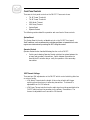
Tx1AudioOn
Tx2AudioOn
Tx1Fault
Tx2Fault
HeartBeat
AntennaPos1
AntennaPos2
Shutdown
VOX
Attack
Timeout
VOX
Decay
Timeout
Operator
Restart
Tx1RF
Power
Threshold
Tx2RF
Power
Threshold
Transmitter Power Threshold
The power threshold controls set the low power switching points on the FM RTC.
The adjustments ranges from 5 to 500 watts.
•Tx1 RF Power sets the RF low power point where the FM RTC switches from
the primary to the secondary transmitter. The rf power must drop below the
threshold for longer than 4 seconds before the FM RTC switches to the
secondary transmitter.
•Tx2 RF Power sets the RF low power point where the FM RTC shuts down the
system if it is operating on the secondary transmitter. The secondary trans-
mitter RF power must drop below the threshold for longer than 4 seconds
before system shutdown.

7
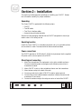
Section 2—Installation
This section provides important guidelines for installing your FM RTC. Review
this information carefully for proper installation.
Unpacking
The Crown FM RTC is packed with the following items.
• FM RTC
•Two RF cables
• Two 15-pin interface cables
• Antenna relay with attached cable
Save the box and packaging material that the FM RTC was packed in should you
need to return it for factory service.
Operating location
Install the Crown FM RTC in a standard component rack or on a suitable surface
such as a bench or desk. The area should be clean and well ventilated.
Power connections
The FM RTC operates on 90-264 volts AC, 50-60 Hz single phase. Use the supplied
EIA power cord to connect power to the FM RTC.
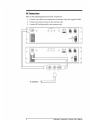
Mounting and connecting
1. Mount the transmitters in an equipment rack or other suitable enclosure.
Connect transmitter power and program audio following instructions in
transmitter’s manual.
2. Mount FM RTC in rack or other suitable enclosure near the transmitters.
3. Mount antenna relay in the back of the rack.
4. Connect ground stud on back of FM RTC to station system ground.
5. Connect interconnect cables between transmitter interface connectors and
transmitter IO connectors.
6. Connect the antenna relay to the relay connector on back of the FM RTC.
Aux
I/OPort
1
96
5
Antenna
Switch
1
96
5
Ground
Tx2RemoteI/O
15
9
1
8
Tx1RemoteI/O
15
9
1
8


9
3.0 Seconds
(0%)
15 Seconds
(25%)
30 Seconds
(50%)
1.0 Minutes
(75%)
2.0 Minutes
(100%)
5.0 Watts
(0%)
30 Watts
(25%)
100 Watts
(50%)
500Watts
(100%)
250 Watts
(75%)
Section 3—Operation
This section provides general operating parameters of your transmitter and a
detailed description of its front panel display.
Start up sequence
This section describes the starting sequence for a Crown FM RTC system. Startup
consists of two parts:
• Presetting controls
• Power up
Presetting controls
Before starting the FM RTC system, preset the following controls.
• Transmitter Power Threshold-Set below the maximum operating power of
each transmitter.
• VOX Attack Timeout
• Vox Attack Delay Timeout
Power up
The following steps describe the Crown FM RTC startup sequence. Before
beginning the startup sequence, verify all connections.
1. Verify or set the power switch on the FM RTC to off (down).
2. Verify or set the transmitter carrier switches to off.
3. Verify or set the circuit breakers on the back of the transmitters on (up).
4. Set power switch on FM RTC to on (up). The front panel indicators will cycle
through a startup sequence. The Heart Beat LED will flash regularly, about
once per second.
5. Set transmitter carrier switches to on (up). The primary transmitter will
begin to transmit.
End of day operation
At the end of the programming day, the FM RTC turns off both the primary and
secondary transmitter carriers. This occurs only when both primary and
secondary audio sources are lost or shut down. The FM RTC restores operation as
soon as either or both audio sources are restored.
Power Threshold VOX Timeout

10
Redundant Transmitter Controller User’s Manual
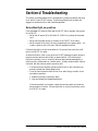
Section-4 Troubleshooting
This section provides guidelines for troubleshooting common problems that may
occur with a Crown FM RTC system. The following subsections list tests and
suggest corrective actions for each identified problem.
No heartbeat light, no operation,
If the Heartbeat LED does not flash and the FM RTC fails to operate, verify power
to the FM RTC.
• Verify that AC power (90 to 264 Volts AC, 50-60 Hz) is present at the power
cord.
• Verify that the power switch on the back of the FM RTC is turned on.
• Verify the state of the fuse. The fuse is located next to the power switch. If it
is open, replace it with a 1/2 Amp, 250 Volt standard blow fuse.
If these checks fail to correct the problem or if the power fuse continues to fail,
return the FM RTC for repair.
An Antenna Position Fault occurs when the FM RTC attempts to switch antenna
positions and the antenna switch fails to respond within a 100 milliseconds.
Faults are not likely to occur unless the antenna relay has been damaged by a
lightning strike, excess power or a similar event. A faulty antenna switch cable or
connector will also cause an antenna position fault.
• If a transient event caused the antenna switch fault, it will clear when you
press and release the System Reset button.
• To verify that the antenna fault did not occur while trying to switch to the
secondary transmitter:
1. Disable the primary transmitter audio.
2.Press and release the System Reset button.
If the antenna fault occurs again, replace the antenna switch and reset the
antenna switch interface. If these checks fail to correct the problem, return
the FM RTC for repair.

11
No Audio Signal Detected
The FM RTC Tx1 and Tx2 Audio On indicators illuminate when the FM RTC is
detecting audio from the transmitters.
Should the FM RTC indicate a loss of either audio source.
• Verify that the transmitter has program audio connected to the audio input.
• Verify that the transmitter output audio is connected to the FM RTC Remote
I/O channel
• Verify that the audio level is approximately 12 volts peak-to-peak.
If these checks fail to correct the problem, return the FM RTC for repair.
Excessive or insufficient VOX time
VOX Attack and Decay time settings are front panel adjustable from 3.0 to 120
seconds. If the VOX Attack and Decay controls fail to adjust the appropriate
timeouts, return the FM RTC for repair.
RF power settings
The Tx1 and Tx2 RF Power Threshold settings set the low power threshold from
5.0 to 500 watts. If the RF Power Threshold Adjust controls fail to adjust the
appropriate levels, return the FM RTC for repair.
Tx1 or Tx2 fault locked out
The FM RTC features a fault counter for each of the transmitters. Should a
transmitter experience a recurring fault, such as a SWR or RF Power fold-back, the
faulting transmitter shall be locked out after the sixth fault/recovery/fault cycle.
To prevent false transmitter fault lockouts, the counter is decremented every 4
minutes. In the event that a transmitter is fault locked out, either reset the
FM RTC or press the System Reset button to resume operation.

Service
The product warranty (see opposite page) outlines our responsibility for defective products.
Before returning a product for repair or replacement (our choice), call our Customer Service
department using the following telephone number:
(866) 262-8917
Our Customer Service Representative will give you further instructions regarding the return
of your product. Use the original shipping carton or a new one obtained from Crown. Place
shipping spacers between the slide-out power amplifier assembly and the back panel.
Please fill out the Factory Service Instructions sheet (page 7–5) and include it with your re-
turned product.
24–Hour Support
In most instances, what you need to know about your product can be found in this manual.
There are times when you may need more in-depth information or even emergency-type
information. We provide 24–hour technical assistance on your product via a toll telephone
call. For emergency help or detailed technical assistance, call
(866) 262-8917
You may be required to leave a message at this number but your call will be returned
promptly from our on-call technician.
Spare Parts
To obtain spare parts, call Crown Broadcast Service at the following number.
(866) 262-8917
You may als
o write to the following a
ddress:
International Radio
& Electronics Corporation
25166 Leer Drive
Elkhart, Indiana, U.S.A. 46514-5425
5HGXQGDQW7UDQVPLWWHU&RQWUROOHUUser’s Manual

13
Three-YThree-Y
Three-YThree-Y
Three-Y
ear Limited Wear Limited W
ear Limited Wear Limited W
ear Limited W
arrantyarranty
arrantyarranty
arranty
North America Only
SUMMARY OF WARRANTY
We, Crown Broadcast, a business unit of International Radio and Electronics Company, Inc., 25166 Leer
Drive, Elkhart, Indiana 46515–2000 warrant to the ORIGINAL PURCHASER of a NEW Crown Broadcast
product, for a period of three (3) years from the date of purchase by the original purchaser (the “war-
ranty period”) that the new Crown Broadcast product is free of defects in materials and workmanship and
will meet or exceed all advertised specifications for such a product. This warranty does not extend to any
subsequent purchaser or user, and automatically terminates upon sale or other disposition of our prod-
uct.
ITEMS EXCLUDED FROM THIS CROWN BROADCAST
We are not responsible for product failure caused by misuse, accident, or neglect. This warranty does not
extend to any product on which the serial number has been defaced, altered, or removed. It does not
cover damage to loads or any other products or accessories resulting from Crown Broadcast product
failure. It does not cover defects or damage caused by use of unauthorized modifications, accessories,
parts, or service.
WHAT WE WILL DO
We will remedy any defect, in material or workmanship (except as excluded), in our sole discretion, by
repair, replacement, or refund. If a refund is elected, then you must make the defective or malfunction-
ing component available to us free and clear of all liens or other encumbrances. The refund will be equal
to the actual purchase price, not including interest, insurance, closing costs, and other finance charges
less a reasonable depreciation on the product from the date of original purchase. Warranty work can only
be performed at our authorized service centers or at our factory. Expenses in remedying the defect will be
borne by Crown Broadcast, including two-way surface freight shipping costs within the United States.
(Purchaser must bear the expense of shipping the product between any foreign country and the port of
entry in the United States and all taxes, duties, and other custom’s fee(s) for such foreign shipments.)
HOW TO OBTAIN WARRANTY SERVICE
You must notify us of your need for warranty service not later than ninety (90) days after the expiration
of the warranty period. We will give you an authorization to return the product for service. All compo-
nents must be shipped in a factory pack or equivalent which, if needed, may be obtained from us for a
nominal charge. Corrective actions will be taken within a reasonable time of the date of receipt of the
defective product by us. If the repairs made by us are not satisfactory, notify us immediately.
DISCLAIMER OF CONSEQUENTIAL AND INCIDENTAL DAMAGES
You are not entitled to recover from us any consequential or incidental damages resulting from any
defect in our product. This includes any damage to another product or products resulting from such a
defect.
WARRANTY ALTERATIONS
No person has the authority to enlarge, amend, or modify this warranty. The warranty is not extended by
the length of time for which you are deprived of the use of the product. Repairs and replacement parts are
provided under the terms of this warranty shall carry only the unexpired portion of this warranty.
DESIGN CHANGES
We reserve the right to change the design of any product from time to time without notice and with no
obligation to make corresponding changes in products previously manufactured.
LEGAL REMEDIES OF PURCHASER
There is no warranty which extends beyond the terms hereof. This written warranty is given in lieu of any
oral or implied warranties not contained herein. We disclaim all implied warranties, including without
limitation any warranties of merchantability or fitness for a particular purpose. No action to enforce this
warranty shall be commenced later than ninety (90) days after expiration of the warranty period.
Crown Broadcast, International and Radio Company, Inc.
25166 Leer Drive, P.O. Box 2000, Elkhart, Indiana 46515–2000
Phone: (219) 262-8900; FAX: (219) 262-5399
Revised August 2001

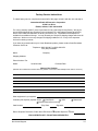
Factory Service Instructions
To obtain factory service, complete the bottom half of this page, include it with the unit, and ship to:
International Radio
& Electronics Corporation
25166 Leer Drive
Elkhart, Indiana, U.S.A. 46514-5425
For units in warranty (within
years of p
urchase from any authorized Crown Dealer): We pay for
ground UPS shipments fro
m anywhere in the continental U.S. and Federal Express Second Day
service from Hawaii and Alaska to the factory and back to you. Expedited service/shipment is
available for an additional charge. You may forward your receipt for shipping charges which we will
reimburse. We do not cover any charges for shipping outside the U.S. or any of the expenses
involved in clearing customs.
If you have any questions about your Crown Broadcast product, please contact Crown Broadcast
Customer Service at:
Telephone: (866) 262-8917 or (866) 262-8972
Fax: (
866) 262-8909
Name: Company:
Shipping Address:
Phone Number: Fax:
Model: Serial Number: Purchase Date:
Nature of the Problem
(Describe the conditions that existed when the problem occurred and what attempts were made to correct it.)
Other equipment in your system:
If warranty has expired, payment will be: Cash/Check VISA Mastercard
Please Quote before servicing
Card Number: Exp. Date: Signature:
Return Shipment Preference if other than UPS Ground: Expedite Shipment Other
ENCLOSE WITH UNIT—DO NOT MAIL SEPARATELY
Service and Support 7-5
-
 1
1
-
 2
2
-
 3
3
-
 4
4
-
 5
5
-
 6
6
-
 7
7
-
 8
8
-
 9
9
-
 10
10
-
 11
11
-
 12
12
-
 13
13
-
 14
14
-
 15
15
-
 16
16
-
 17
17
-
 18
18


Crown FM-1 Owner's manual
- Type
- Owner's manual
- This manual is also suitable for
Ask a question and I''ll find the answer in the document
Finding information in a document is now easier with AI
Related papers

Other documents
-
Delta TRDS094-W Installation guide
-
-
Magnadyne MV-TX2 Installation guide
-
 Crown Broadcast E Series 20-100 User manual
-
 Crown Broadcast E Series 350-2000 User manual
-
 Crown Broadcast FM250G Owner's manual
-
 Crown Broadcast FM600 User manual
-
 Crown Broadcast FM600 User manual
-
 Crown Broadcast Classic LPFM User manual
-
Ericsson RBS 2206 Reference guide


