Page is loading ...

2
• In order to protect the unit during installation, it is recommended to put a piece of cardboard in the bottom of the unit.
- Electric drill
- 1/8’’ drill bit
- 1/4’’ masonry drill bit
- Tape measure
- Pencil
- Philips- or Robertson-head screwdriver #1
- Level, Square
- Safety glasses
- Caulking gun
- Silicone-based caulk (high quality mold-resistant)
- White spirit (thinner)
- Clean soft cloths
If you need spare parts, do not return the shower
door to the store, but call us; you will be answered
courteously and immediately. See contact information
at the back of this manuel.
Model number
Item no.
Description
To help identify the proper parts, please refer to the
spare parts illustrations. Hardware is represented at
its actual length.
Use only soft detergents or soapy water applied with a soft cloth. Always
rinse carefully after cleaning, and blot dry using a damp cloth or a
chamois. It is recommended to use a rubber squeegee after each shower
to remove water stains from the inside of the glass panels. To keep the
new appearance of your shower door, use scouring pads, rough
cloths, cutting instruments, or strong or abrasive cleaners on the metal
parts, the wall or the glass panels.
Remove superficial scratches using automotive polish or automotive
polishing liquid followed with automotive polish.

3
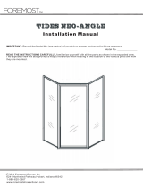
NEO-ANGLE frAmELEss cOrNEr shOwEr dOOr

4
Exposed
surface
Type A
Exposed
surface
Type B
10,92
4,57
127
R
2,29
609,60
1158,88
1641,48
L
0.5
A
TYP.4
D
E
E
E
E
F
G
4,32
Typ 4
101,60
19,06
623,32
1145,16
1666,88
E
E
E
E
Assembled view
D
Exploded view
Bubble seal
# 10048850
10018942-XXX-600
Wall Chanel
69 5/8
SAP Number
Old Number
Description
length
SAP Number
Old Number
Description
length
REV.
DESCRIPTION
DATE
BY
REVISIONS
G
Tolerances changed from 0.05 & 0.1 to
0.15 & 0.4.
2007-08-10
PB
F
Change tolerance from 0.8mm to
0.5mm
2007-08-03
PB
E
Change point of mesurement &
Tolerance from 0.8mm to 0.4 mm for
dimensions longuer than 150mm
2007-07-25
PB
D
Change tolerance and add information
about tolerance and M-Spec in Notes
6/19/2007
BP
C
Change dimensions from imperial to
metric
2007-06-14
PB
B
Add tolerances and positionning of
mesurements
2007-06-14
PB
A
Add Length & assembly information
Oct/03/200
6
PB
SHEET 1 OF 1
SCALE: 1:1
DWG. NO.
TITLE:
NAME
DATE
CHECKED BY
DRAWN BY
THIS DOCUMENT AND THE INFORMATION IT
CONTAINS ARE THE EXCLUSIVE PROPERTY OF
MAAX CANADA INC. AND ARE PROPRIETARY AND
CONFIDENTIAL. NEITHER THIS DOCUMENT NOR ANY
OF THE INFORMATION CONTAINED IN IT MAY BE
USED BY YOU FOR ANY PURPOSE WHATSOEVER,
NOR REPRODUCED OR DISCLOSED BY YOU TO
OTHERS, EXPECT WTIH THE EXPRESS PRIOR
WRITTEN CONSENT OF MAAX CANADA INC.
160 St-Joseph Blvd.
Lachine, Québec, H8S 2L3
Tel.: (514) 634-8981
Fax: (514) 634-7844
10018942-M
Wall_Chanel_M
Philippe Bélanger
Ramy Sydhom
june 14,07
Sept/28/2006
Surface finish
(unless otherwise specified)
Notes:
µmm
3.2
µin
125
MM
X
INCHES
- Unless otherwise specified all tolerances to be
+/-
0.40mm
- Refer to M-Spec (M-01-EN-B)
- Standard Aluminum Association tolerances apply unless
otherwise noted.
- Tolerance for holes diameter ±0.15 mm
- Tolerance for hole position ±0.4 mm
- Denotes Critical Dimensions to be checked
G
G
VENDOR ACCEPTANCE
PLEASE SIGNIFY BELOW THAT YOU HAVE EXAMINED THE ABOVE
DRAWING(S) AND ARE CAPABLE TO REPRODUCE AS PER ALL THE
SPECIFICATIONS AND THAT YOU AGREE TO ACCEPT ALL
RESPONSIBILITIES FOR NON CONFORMITY WITH THE ABOVE
DRAWING(S).
DRAWING REVISION:
SIGNED BY:
VENDOR:
DATE:
A
Anchoring plug
F
‘‘A’’ glass clip
10
Glass clip tab
G
‘‘B’’ glass clip
B
Wall bracket screw
#8 x 1’’
C
Assembly screw
#8 x 3/4’’
E
Glass clip screw
#7 x 7/16’’
3/4
D
Wall bracket screw
M4 x 7/16’’
H
Wall bracket latch
4
PVC seal
7
Upper and
lower rail
5
Wall bracket
6
Adjustable
wall bracket
10
Quadrex screw
SHEET 1 OF 1
SCALE: 5:1
DWG. NO.
TITLE:
NAME
DATE
CHECKED BY
DRAWN BY
THE INFORMATION CONTAINED IN THIS
DRAWING IS THE SOLE PROPERTY OF
MAAX CANADA INC. ANY REPRODUCTION
IN PART OR AS A WHOLE WITHOUT THE
WRITTEN PERMISSION OF MAAX CANADA
INC. IS PROHIBITED.
160 St-Joseph Blvd.
Lachine, Québec, H8S 2L3
Tel.: (514) 634-8981
Fax: (514) 634-7844
Screw walljamb
Locking screw wal ljamb
Surface finish
(unless otherwise specified)
Notes:
- Unmarked Radius = 0.015"
- Break all Corners with R 0.015" unless otherwise specified
- Denotes Critical Dimensions to be checked
µmm
xxx
µin
xxx
MM
INCHES
Philippe Belanger
Jul.26, 2007
X
0
VENDOR ACCEPTANCE
PLEASE SIGNIFY BELOW THAT YOU HAVE EXAMINED THE ABOVE
DRAWING(S) AND ARE CAPABLE TO REPRODUCE AS PER ALL THE
SPECIFICATIONS AND THAT YOU AGREE TO ACCEPT ALL
RESPONSIBILITIES FOR NON CONFORMITY WITH THE ABOVE
DRAWING(S).
DRAWING REVISION:
SIGNED BY:
VENDOR:
DATE:
0
8
Handle
assembly
3/4

5
B
Assemble the structure as indicated on the figure below, using
#8 x 3/4’’ screws, as indicated.
Use the help of a second person to support the rails
during assembly, or perform the assembly flat on the ground,
after protecting the surfaces with a blanket.
B
This task requires two people.
Assemble the wall brackets
as illustrated in the above
figure
This task should be
performed in two steps.
x2

6
+45º
The bottom of the
wall posts must be filed
to adjust for installation
on a single-hull unit.
Wall bracket
front view.
Lift the frame assembly and position
it on the base. Center the frame
from left to right, as illustrated in the
figure.
By positioning the frame over the
base, the wall posts can be pushed
further back inside the panel posts.
Using a pencil, makes sure that
the wall posts are plumb, and mark
a line with a pencil inside the wall
post to mark its position on the wall, as
illustrated in the figure.
While a person holds the shower frame
in position, the other should makes sure
that wall posts are in contact with the wall.
If required, wall posts can be removed or
inserted. Remove the shower unit from
the base and remove the wall posts from
the panel posts.
Reinstall the wall posts on the wall
at the marked location. The wall
post lower edges must align with the
pencil marks, as illustrated on the figure.
Using a pencil, mark all attachment
hole locations, as illustrated in
the figure.
Remove the wall posts and drill
holes at each attachment location,
as illustrated in the figure.
For installation on ceramics tiles, use a
1/4’’masonry bit.
Using a center punch, punch the ceramics
surface at the location of the attachment
points. Drill, then insert plugs.
For installation on an acrylic enclosure,
use a 1/8’’bit. Plugs are not required.
Reinstall the wall posts and attach
them to the wall with #8 x 1’’ , screws,
as illustrated in the figure. Wall posts
are equipped with for better horizontal
adjustment.

7
Lift the frame and maneuver it so that a panel post engages
into the wall profile, as indicated on the figure.
Then, rotate [the shelf] until the other panel post engages
into the other wall profile, as indicated on the figure. Center
the frame over the base threshold.
A
B
Lightly tighten the top and bottom
screw to hold the structure in place
View from inside of
shower cabin
A
DETAIL A
SCALE 1 : 3
Panel post
groove
View from inside
of shower cabin
View from inside
of shower cabin
Slide the glass panel
Insert a glass panel in the glass profile of the FRAME, as
indicated on the figure.
The glass panel then rests on a rail shelf.
Secure the glass panel in position using ‘‘A’’ and ‘‘B’’ glass clips
and # 7 x 7/16’’ screws, as indicated on the figure.
Repeat the procedure for the glass panel on the other side.
x2 x2

8
A
DETAIL A
SCALE 1 : 3
Make sure that the shower cabin is centered over the base
threshold.
Make sure that the rail is laying flat and evenly on the base and
perform any necessary adjustment.
Tighten fully the wall post lower face screws to secure the
structure in place, as indicated on the figure.
View from inside
of shower cabin
View from inside
of shower cabin
Working inside the shower cabin, install the window tabs, as
indicated on the right hand figure.
Install from the bottom of the glass panel the tab [sic]. If necessary,
use a flat and dull tool (paint mixer, for example) to push the tab
between the glass panel and the panel post GROOVE.
In order to properly install the tab, be careful that its wider side
point toward the glass panel. Cut excess length at the top.
Repeat the procedure for the other side.
Wide side toward
glass panel
View from inside
of shower cabin
x2

9
1- Start by disassembling the handle set.
2- Insert the aluminum plat (3), the clear gasket (2) and the round bushing (1)
into the special screw (4).
3- Insert the assembly through the glass panel as shown on the illustration, the
screw head should be on the inside of the shower.
4- Insert the clear gasket (2) on the screw, on the other side of the glass panel.
5- Repeat step 2 to 4 for the bottom of the handle.
6- Using a Philips screwdriver, tighten the screw (4) onto the outside handle (8)
for the top and bottom of the handle.
7- Insert the inside handle (5) in the screw heads.
8- Using the provided Allen key, tighten the setscrews on the screw to secure
the handle in place.
Note: Use the longer side of the Allen key to screw the setscrews; it can be
angled to facilitate the process. Use the shorter side of the Allen key to securely
tighten the setscrews.
5
1
4
2
7
6
3
8
Turn the screw clockwise to raise, and
counterclockwise to lower.
Roller top view.
1- Enter the shower cabin. Lift the
door and tilt it forward to be able
to rest the top rollers in the upper
rail grooves.
2- Press the lower roller engagement
buttons and push for the doors.
Lower rollers must be aligned in the
lower rail grooves.
3- Use the leveling screws on the
top of each door panel to move the
door to its heighest point without
forcing the screws.
Doors should open and close easily Close the doors so that
magnetic strips contact each other, in order to see whether
adjustment is required. Top of doors should be at the same
height, and the space between doors, when they close, should
be uniform.
If the two doors require adjustment, raise or lower one of the
roller assemblies (or both of them) using the top-mounted
adjustment screw.
x2
B
A
A
B
Groove for rollers.
Glass panel
Inside shower
Outside
shower

10
Note: Apply silicone caulk to the locations outside the shower cabin.
With the sliding doors fully open, install the door seal on the edge of the stationary panel, as indicated on the figure. Cut it as
required.
: The door seal lip must face inside the cabin, as indicated. Repeat the procedure for the other stationary panel.
The lip is facing
toward the cabin
x2

11
Problem Cause Solution
The aluminum frame is not level Level the aluminum frame
The aluminum frame is tighten to the wall
channel
Untighteen the frame from the wall channel
The door panel comes out of the
bottom track
The door panel is not at its highest point
Use the leveling screws on the top of each
door panel to move the door to its heights
point
The door magnets do not seal
properly
The doors are not level
Using the leveling screws on the top of each
door panel to level the doors.
The handles leak The main screw is not tighten fully
Remove the inside handle and retighten the
screw
The fixed glass panels do not fit
in the aluminum frame
If you experience any fo the following difficulties while installing your shower door, use this troubleshooting guide to
help remedy the problem before contacting our support department. Should the problem persist, please contact our
support department.

14
A
Cheville d’ancrage
F
Clip de vitre
«A»
10
Languette
de vitre
G
Clip de vitre
«B»
B
Vis de montant mural
n° 8 x 1 po
C
Vis d’assemblage
n° 8 x 3/4 po
E
Vis de clip à verre
n° 7 x 7/16 po
3/4
D
Vis de façonnage des
montants muraux
M4 x 7/16 po
H
Barrure des
montants muraux
4
Joint
d’étanchéité en
PVC
7
Rail supérieur
et inférieur
5
Montant
mural
6
montant mural
ajustable
Exposed
surface
Type A
Exposed
surface
Type B
10,92
4,57
127
R
2,29
609,60
1158,88
1641,48
L
0.5
A
TYP.4
D
E
E
E
E
F
G
4,32
Typ 4
101,60
19,06
623,32
1145,16
1666,88
E
E
E
E
Assembled view
D
Exploded view
Bubble seal
# 10048850
10018942-XXX-600
Wall Chanel
69 5/8
SAP Number
Old Number
Description
length
SAP Number
Old Number
Description
length
REV.
DESCRIPTION
DATE
BY
REVISIONS
G
Tolerances changed from 0.05 & 0.1 to
0.15 & 0.4.
2007-08-10
PB
F
Change tolerance from 0.8mm to
0.5mm
2007-08-03
PB
E
Change point of mesurement &
Tolerance from 0.8mm to 0.4 mm for
dimensions longuer than 150mm
2007-07-25
PB
D
Change tolerance and add information
about tolerance and M-Spec in Notes
6/19/2007
BP
C
Change dimensions from imperial to
metric
2007-06-14
PB
B
Add tolerances and positionning of
mesurements
2007-06-14
PB
A
Add Length & assembly information
Oct/03/200
6
PB
SHEET 1 OF 1
SCALE: 1:1
DWG. NO.
TITLE:
NAME
DATE
CHECKED BY
DRAWN BY
THIS DOCUMENT AND THE INFORMATION IT
CONTAINS ARE THE EXCLUSIVE PROPERTY OF
MAAX CANADA INC. AND ARE PROPRIETARY AND
CONFIDENTIAL. NEITHER THIS DOCUMENT NOR ANY
OF THE INFORMATION CONTAINED IN IT MAY BE
USED BY YOU FOR ANY PURPOSE WHATSOEVER,
NOR REPRODUCED OR DISCLOSED BY YOU TO
OTHERS, EXPECT WTIH THE EXPRESS PRIOR
WRITTEN CONSENT OF MAAX CANADA INC.
160 St-Joseph Blvd.
Lachine, Québec, H8S 2L3
Tel.: (514) 634-8981
Fax: (514) 634-7844
10018942-M
Wall_Chanel_M
Philippe Bélanger
Ramy Sydhom
june 14,07
Sept/28/2006
Surface finish
(unless otherwise specified)
Notes:
µmm
3.2
µin
125
MM
X
INCHES
- Unless otherwise specified all tolerances to be
+/-
0.40mm
- Refer to M-Spec (M-01-EN-B)
- Standard Aluminum Association tolerances apply unless
otherwise noted.
- Tolerance for holes diameter ±0.15 mm
- Tolerance for hole position ±0.4 mm
- Denotes Critical Dimensions to be checked
G
G
VENDOR ACCEPTANCE
PLEASE SIGNIFY BELOW THAT YOU HAVE EXAMINED THE ABOVE
DRAWING(S) AND ARE CAPABLE TO REPRODUCE AS PER ALL THE
SPECIFICATIONS AND THAT YOU AGREE TO ACCEPT ALL
RESPONSIBILITIES FOR NON CONFORMITY WITH THE ABOVE
DRAWING(S).
DRAWING REVISION:
SIGNED BY:
VENDOR:
DATE:
10
Quadrex screw
SHEET 1 OF 1
SCALE: 5:1
DWG. NO.
TITLE:
NAME
DATE
CHECKED BY
DRAWN BY
THE INFORMATION CONTAINED IN THIS
DRAWING IS THE SOLE PROPERTY OF
MAAX CANADA INC. ANY REPRODUCTION
IN PART OR AS A WHOLE WITHOUT THE
WRITTEN PERMISSION OF MAAX CANADA
INC. IS PROHIBITED.
160 St-Joseph Blvd.
Lachine, Québec, H8S 2L3
Tel.: (514) 634-8981
Fax: (514) 634-7844
Screw walljamb
Locking screw wal ljamb
Surface finish
(unless otherwise specified)
Notes:
- Unmarked Radius = 0.015"
- Break all Corners with R 0.015" unless otherwise specified
- Denotes Critical Dimensions to be checked
µmm
xxx
µin
xxx
MM
INCHES
Philippe Belanger
Jul.26, 2007
X
0
VENDOR ACCEPTANCE
PLEASE SIGNIFY BELOW THAT YOU HAVE EXAMINED THE ABOVE
DRAWING(S) AND ARE CAPABLE TO REPRODUCE AS PER ALL THE
SPECIFICATIONS AND THAT YOU AGREE TO ACCEPT ALL
RESPONSIBILITIES FOR NON CONFORMITY WITH THE ABOVE
DRAWING(S).
DRAWING REVISION:
SIGNED BY:
VENDOR:
DATE:
0
3/4
8
Assemblage
de la poignée

24
A
Clavija de anclaje
10
Lengüeta para
el vidrio
B
Tornillo para el
montante de pared
N.° 8 X 1 pulgada
C
Tornillo de ensamblado
n.° 8 x 3/4 pulgadas
E
Tornillo para la presilla sujeta-vidrio
n.° 7 x 7/16 pulgadas
3/4
D
Tornillo de montaje de
los montantes de pared
M4 x 7/16 pulgadas
H
Barras de los
montantes de pared
4
Junta de
estanqueidad
de PVC
7
Rail superior
e inferior
5
Montante
de pared
6
Montant mural
ajustable
Exposed
surface
Type A
Exposed
surface
Type B
10,92
4,57
127
R
2,29
609,60
1158,88
1641,48
L
0.5
A
TYP.4
D
E
E
E
E
F
G
4,32
Typ 4
101,60
19,06
623,32
1145,16
1666,88
E
E
E
E
Assembled view
D
Exploded view
Bubble seal
# 10048850
10018942-XXX-600
Wall Chanel
69 5/8
SAP Number
Old Number
Description
length
SAP Number
Old Number
Description
length
REV.
DESCRIPTION
DATE
BY
REVISIONS
G
Tolerances changed from 0.05 & 0.1 to
0.15 & 0.4.
2007-08-10
PB
F
Change tolerance from 0.8mm to
0.5mm
2007-08-03
PB
E
Change point of mesurement &
Tolerance from 0.8mm to 0.4 mm for
dimensions longuer than 150mm
2007-07-25
PB
D
Change tolerance and add information
about tolerance and M-Spec in Notes
6/19/2007
BP
C
Change dimensions from imperial to
metric
2007-06-14
PB
B
Add tolerances and positionning of
mesurements
2007-06-14
PB
A
Add Length & assembly information
Oct/03/200
6
PB
SHEET 1 OF 1
SCALE: 1:1
DWG. NO.
TITLE:
NAME
DATE
CHECKED BY
DRAWN BY
THIS DOCUMENT AND THE INFORMATION IT
CONTAINS ARE THE EXCLUSIVE PROPERTY OF
MAAX CANADA INC. AND ARE PROPRIETARY AND
CONFIDENTIAL. NEITHER THIS DOCUMENT NOR ANY
OF THE INFORMATION CONTAINED IN IT MAY BE
USED BY YOU FOR ANY PURPOSE WHATSOEVER,
NOR REPRODUCED OR DISCLOSED BY YOU TO
OTHERS, EXPECT WTIH THE EXPRESS PRIOR
WRITTEN CONSENT OF MAAX CANADA INC.
160 St-Joseph Blvd.
Lachine, Québec, H8S 2L3
Tel.: (514) 634-8981
Fax: (514) 634-7844
10018942-M
Wall_Chanel_M
Philippe Bélanger
Ramy Sydhom
june 14,07
Sept/28/2006
Surface finish
(unless otherwise specified)
Notes:
µmm
3.2
µin
125
MM
X
INCHES
- Unless otherwise specified all tolerances to be
+/-
0.40mm
- Refer to M-Spec (M-01-EN-B)
- Standard Aluminum Association tolerances apply unless
otherwise noted.
- Tolerance for holes diameter ±0.15 mm
- Tolerance for hole position ±0.4 mm
- Denotes Critical Dimensions to be checked
G
G
VENDOR ACCEPTANCE
PLEASE SIGNIFY BELOW THAT YOU HAVE EXAMINED THE ABOVE
DRAWING(S) AND ARE CAPABLE TO REPRODUCE AS PER ALL THE
SPECIFICATIONS AND THAT YOU AGREE TO ACCEPT ALL
RESPONSIBILITIES FOR NON CONFORMITY WITH THE ABOVE
DRAWING(S).
DRAWING REVISION:
SIGNED BY:
VENDOR:
DATE:
10
Quadrex screw
SHEET 1 OF 1
SCALE: 5:1
DWG. NO.
TITLE:
NAME
DATE
CHECKED BY
DRAWN BY
THE INFORMATION CONTAINED IN THIS
DRAWING IS THE SOLE PROPERTY OF
MAAX CANADA INC. ANY REPRODUCTION
IN PART OR AS A WHOLE WITHOUT THE
WRITTEN PERMISSION OF MAAX CANADA
INC. IS PROHIBITED.
160 St-Joseph Blvd.
Lachine, Québec, H8S 2L3
Tel.: (514) 634-8981
Fax: (514) 634-7844
Screw walljamb
Locking screw wal ljamb
Surface finish
(unless otherwise specified)
Notes:
- Unmarked Radius = 0.015"
- Break all Corners with R 0.015" unless otherwise specified
- Denotes Critical Dimensions to be checked
µmm
xxx
µin
xxx
MM
INCHES
Philippe Belanger
Jul.26, 2007
X
0
VENDOR ACCEPTANCE
PLEASE SIGNIFY BELOW THAT YOU HAVE EXAMINED THE ABOVE
DRAWING(S) AND ARE CAPABLE TO REPRODUCE AS PER ALL THE
SPECIFICATIONS AND THAT YOU AGREE TO ACCEPT ALL
RESPONSIBILITIES FOR NON CONFORMITY WITH THE ABOVE
DRAWING(S).
DRAWING REVISION:
SIGNED BY:
VENDOR:
DATE:
0
8
Ensamble de
la manija
3/4
F
Presilla sujeta-
vidrio «A»
G
Presilla sujeta-
vidrio «B»

31
Si tiene alguna de las siguientes dificultades al instalar la puerta de su ducha utilice esta guía para resolución de
problemas para solucionar el inconveniente antes de contactar al departamento de soporte. Si el problema persiste,
contáctese con el departamento de soporte.
Problema Causa Solución
Los paneles jos no caben en el marco de
aluminio
El marco de aluminio no está nivelado Nivele el marco de aluminio.
El marco de aluminio está demasiado
ajustado al canal de la pared
Desajuste el marco del canal de la pared.
El panel de la puerta se sale del carril
inferior
El panel de la puerta no está en su punto
más alto
Utilice los tornillos niveladores en la parte su-
perior de cada panel de puerta para moverla
hasta su punto más alto.
Los imanes de la puerta no quedan debi-
damente sellados
Las puertas no están niveladas
Utilice los tornillos niveladores en la parte
superior de cada panel de puerta para
nivelarlas.
Las manijas gotean
El tornillo principal no está totalmente
ajustado
Quite la manija inferior y reajuste el
tornillo.
MAAX Bath Inc. (a continuación “MAAX”) ofrece
un garantía limitada expresa para cada uno
de sus productos. Esta garantía va dirigida
únicamente al propietario o al usuario original
para un uso personal doméstico. En caso de
uso comercial, se aplican otras restricciones.
MAAX garantiza las puertas de ducha y los
paneles de vidrio contra cualquier defecto
de material o de fabricación en condiciones
normales de utilización y mantenimiento
durante un periodo de diez (10) años a
partir de la fecha de compra original del
producto por parte del propietario o usuario,
el contratista o el constructor en un comercio
minorista autorizado.
La presente garantía se extiende al
consumidor o usuario original, pero no se
aplica a la instalación o a cualquier otro costo
de mano de obra.
Salvo en el caso de productos de MAAX
con accesorios de plomería pre-instalados,
MAAX no será responsable bajo circunstancia
alguna por ningún tipo de daño cuando
la instalación de los chorros (jets) o de
cualquier otro accesorio relacionado con el
producto sea realizada por el cliente mismo
o por un instalador designado por el cliente.
MAAX se reserva el derecho de modicar
esta garantía en cualquier momento; se
sobreentiende que dichas modicaciones no
cambiarán las condiciones de la garantía que
se apliquen en el momento de la venta de los
productos en cuestión.
Para obtener el servicio que se ofrece
según lo dispuesto en la presente garantía
durante el horario de atención normal,
deberá comunicarse con el comercio o
distribuidor que le haya vendido el producto,
o directamente con MAAX.
Para obtener mayor información sobre la
garantía limitada de MAAX, consulte el sitio
MAAX Bath Inc. (hereafter “MAAX”) offers
an express limited warranty on each of its
products. This warranty extends only to
the original owner/end-user for personal
household use. For commercial uses,
additional limitations apply.
MAAX warrants shower doors and
glass panels to be free of all material or
workmanship defects under normal use and
service for a period of ten (10) years from
the initial date of purchase by the owner/end-
user, contractor or builder from an authorized
dealer.
This warranty extends to the original consumer
owner, but does not cover installation or any
other labour charges.
Except in the case of MAAX products with
pre-plumbed fixtures, MAAX shall in no event
be liable for damages of any kind when the
installation of jets or any other fixtures related
to the product is done by the customer or the
customer appointed installer.
MAAX reserves the right to modify this
warranty at any time, it being understood that
such modication will not alter the warranty
conditions applicable at the time of the sale of
the products in question.
In order to obtain service provided under
this warranty during regular business hours,
contact the dealer or distributor who sold the
unit, or MAAX directly.
For more information on MAAX’s limited
warranty, please visit
MAAX Bath Inc. (ci-après “MAAX”) offre
une garantie limitée expresse sur chacun
de ses produits. Cette garantie s’adresse
uniquement au propriétaire/utilisateur original
pour un usage personnel domestique. Des
restrictions additionnelles s’appliquent aux
utilisations commerciales.
MAAX garantit les portes de douche et
panneaux de verre contre tout défaut de
matière ou de fabrication dans des conditions
normales d’utilisation et d’entretien pour une
période de dix (10) ans à compter de la date
d’achat initial du produit par le propriétaire/
utilisateur, l’entrepreneur ou le constructeur
auprès d’un distributeur agréé.
La présente garantie s’applique au
consommateur ou utilisateur initial, mais elle
ne s’applique pas à l’installation ou à tout
autre frais de main-d’oeuvre.
Sauf dans le cas des produits MAAX munis
d’accessoires pré-assemblés, MAAX en
aucun cas ne sera responsable de tout
dommage de quelque nature que ce soit
découlant de l’installation des jets ou de tout
autre accessoire associé au produit réalisée
par le client ou un installateur désigné par le
client.
MAAX se réserve le droit de modier cette
garantie en tout temps; il est entendu que
de telles modications ne changeront pas
les conditions de la garantie applicable au
moment de la vente des produits en cause.
Pour se prévaloir du service offert en vertu
de la présente garantie pendant les heures
normales d’ouverture, communiquer avec
le détaillant ou le distributeur qui a vendu le
produit, ou encore avec MAAX directement.
Pour plus de détails concernant la
garantie limitée de MAAX, consulter le

Tel.: 1-800-361-2045
Fax: 1-888-361-2045
Tel : 1-800-328-2531
Fax : 1-800-944-9808
/