Page is loading ...

SERIAL INTERFACE
Series SSW-05
MANUAL OF THE
SERIAL
COMMUNICATION
SSW-05
CODE 0899.4895 E/4


MANUAL OF THE
SERIAL
COMUNICATION
SSW-05
Series: SSW
-
05
Software: Version 2.1X
0899.4895 E/4
WEG AUTOMAÇÃO
Av. Pref. Valdemar Grubba, 3000
89256-900 Jaraguá do Sul, SC – Brasil
Tel.(047)372-4000 – Fax(047)372-4020
email: [email protected]
ATTENTION!
It is very important to
check if the software
version is the same as
indicated above.


_______ Summary _______
SAFETY
NOTICES
1
1.1 Safety Notices in the Manual.......................................
1.2 Safety Notices on the Product ....................................
1.3 Preliminary Recommendations....................................
1
1
2
INTRODUCTION
2
2.1 About this Manual........................................................
2.2 About WEG Protocol....................................................
3
3
COMMUNICATION
INTERFACES
3
3.1 RS-485 Interface..........................................................
3.2 RS-232 Interface.........................................................
3.2.1 RS-232 Electrical Characteristics........................
3.2.2 Cares with RS-232..............................................
3.2.3 RS-232 Connections...........................................
3.2.4 Description of the Soft-Starter Serial Connector.
3.2.5 Definition of the RS-232 Cable............................
3.2.6 Description of the Master Connector (RJ)...........
3.2.7 Definition of the RS-232 PC Cable......................
3.2.8 Description of the PC (DB9) Connector...............
5
7
7
7
8
8
8
8
9
9
DEFINITIONS
4
4.1 Used Terms.................................................................
4.2 Block Diagram..............................................................
4.3 Variable Standardization..............................................
4.4 Character Format.........................................................
4.5 Protocol........................................................................
4.5.1 Reading Telegram...............................................
4.5.2 Writing Telegram.................................................
4.6 Execution and Test Telegram......................................
4.7 Telegram Sequence ....................................................
4.8 Variable Code..............................................................
4.9 Times...........................................................................
10
10
11
13
13
14
15
16
16
17
17
TELEGRAM
EXAMPLES
5
5.1 Example 1....................................................................
5.2 Example 2....................................................................
18
18

VARIABLES OF THE
SERIAL
COMMUNICATION
6
6.1.1 V00 Indication of the Equipment Model...................
6.1.2 V01 Indication of the Soft-Starter Status...................
6.1.3 V02 Indication of the Soft-Starter Errors...................
6.1.4 V03 Logic Command Selection.................................
19
19
20
22
ERRORS AND SERIAL
COMMUNICATION
PARAMETERS
7
7.1 Parameters related to the Serial Communication .......
7.2 Errors Related to the Serial Communication ...............
23
23
DETAILED
PARAMETER
DESCRIPTION
8
8.1 P000 – Access Parameter...........................................
8.2 P002 – Motor Current Indication (%)...........................
8.3 P003 – Motor Current Indication (A)...........................
8.4 P023 – Software Version.............................................
8.5 P030 – R Phase Current..............................................
8.6 P030 – S Phase Current..............................................
8.7 P030 – T Phase Current..............................................
8.8 P050 – Status Indication of the Motor Thermal
Protection .......................................................
8.9 P101 – Initial Voltage (% Un).......................................
8.10 P102 – Time of Acceleration Ramp (s)......................
8.11 P104 – Time of Deceleration Ramp (s)......................
8.12 P105 – Motor Current Setting (%).............................
8.13 P106 – Protection Configuration...............................
8.14 P204 – Load Factory Setting.....................................
8.15 P206 – Auto-Reset Time............................................
8.16 P215 – Keypad Copy Function..................................
8.17 P220 – HMI / (Trimpots and Dip Switch) Selection....
8.18 P264 – Programmable Digital Input DI 1...................
8.19 P277 – Programmable Relay Output (14/23 – 24)....
8.20 P295 – Rated Current of the Soft-Starter..................
8.21 P308 – Network Address...........................................
8.22 P313 – Action of the Serial Communication
Verification.........................................................................
8.23 P314 – Verification Time of the Serial
Communication..................................................................
24
24
24
24
24
24
24
24
25
25
26
26
27
30
30
30
32
32
33
33
33
34
34
TROUBLESHOOTING
9
Problem and Corrective Action..........................................
35

SAFETY NOTICES 1
1
This Manual contains all necessary information for the correct use of the Serial
Communication of the SSW -05 Soft-Starter.
This Manual has been written for qualified personnel with suitable training or technical
qualification to operate serial interfaces and their respective communication protoco ls.
1.1 SAFETY
NOTICES
IN THE MANUAL
The following Safety Notices will be used in this Manual:
DANGER!
If the Safety Instructions are not strictly observed, it can lead
to serious of fatal injuries of personnel and/or equipment
damage.
ATTENTION!
Failure to observe the recommended Safety Procedures can
lead to material damage.
NOTE!
The text aims at to provide important information for the
correct understanding and proper product performance.
1.2 SAFETY
NOTICES ON THE
PRODUCT
The following symbols may be attached to the product,
serving as Safety Notice:
High Voltages.
Components sensitive to electrostatic discharge.
Do not touch them
Mandatory connection to ground protection (PE).
Shield connection to ground.

1 SAFETY NOTICES
2
1.3 PRELIMINARY
RECOMMENDATIONS
DANGER!
Only qualified personnel should plan or implement the
installation, startup, operation and maintenance of serial
interfaces.
Read this manual before attempt any installation and
operation of the Soft-Starter by following carefully all safety
notices here indicated.
Please follow the safety instructions indicated in this Manual,
in the Soft-Starter Manual and/or defined by local
regulations.
If personnel injuries or equipment damages can occurs due
to motors driven by motor starters, please provide always the
required electromechanical safety devices.
If remote control (via serial interface) is used, please take all
required precautions to avoid personnel injuries and
machine and installations damages.
Failure to comply with these instruction may result in
personnel injury and/or equipment damage.
DANGER!
Always disconnect the equipment from the power supply
before open it.
ATTENTION!
The electronic boards are fitted with components sensitive to
electrostatic discharges. Never touch any electrical
component or connector directly. If necessary to do so, touch
before the properly grounded metallic frame or use a suitable
ground strap.
NOTE!
In general, communication networks are sensitive to
interference generated by other equipment. In this case,
please follow all recommended instructions.

INTRODUCTION 2
3
2.1 ABOUT THIS
MANUAL
This Manual describes how to install, start-up, operate and
identify problems related do the serial interface of WEG Soft-
Starters.
For more information, training or services, please contact:
WEG Service:
WEG AUTOMAÇÃO
Tel. (0800) 475767
Fax: (047) 372-4020
NOTE!
If you need information or services, please make available
following data:
þ model of WEG product;
þ serial number and manufacturing date as indicated on
WEG product nameplate;
þ version of installed software.
2.2 ABOUT WEG
PROTOCOL
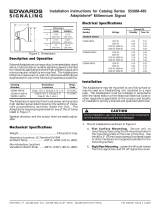
The main purpose of the serial network communication is
the physical connection of several equipment to one or more
masters connected to this network through only one or two
pair of wires:
WEG Soft-Starters are fitted with control software for the
transmission/reception of data through the serial interface to
enable the data reception sent by the master and the data
sending requested by the same.
MESTRE
ESCRAVO 2
(conversor)
ESCRAVO 1
(conversor)
ESCRAVO n
(conversor)
n <= 30
. . .
PC, CLP, etc.
Master
Slave 2
(inverter)
Slave n
(inverter)
Slave 1
(inverter)

2 INTRODUCTION
4
The transfer rate is 9.600Bps, following an exchange
protocol, type question/answer, meeting ISO 1745 standard
for the data transmission in code.
The master is able to realize the following operations related
to each WEG equipment connected to the network:
þ Identification:
• Network number;
• Soft-Starter type (model);
• Software version.
þ Commands:
• general enabling/disabling;
• error reset.
þ Status Recognition:
• enabling/disabling;
• in acceleration;
• at rated voltage;
• in deceleration;
• in error.
þ Parameter Reading or Changing.
Typical examples of WEG network use:
• Supervisory monitoring at the same time several variables
of WEG Soft-Starters;
• PLC controlling the operation of several WEG Soft-
Starters WEG in an industrial process.
NOTE!
WEG protocol is the same for all WEG equipment, but the
logic command words, the basic variables and the
parameters can differ among equipment.

COMMUNICATION INTERFACES 3
5
The physical connection between WEG Soft-Starters is
performed according to one of the standards below:
þ RS-232 point to point, up to 10m (32.8 ft);
þ RS-485 multipoint, with the use of the MIW-02 serial
interface module, with galvanic insulation, up to 1000m
(3280 ft).
3.1 RS-485 INTERFACE
For the serial communication of the Soft-Starters at WEG
network.
þ The interface allows the interconnection of up to 30 WEG
Soft-Starters to one master, attributing to each WEG
equipment one address (1 to 30) that has to be set.
þ In addition to these 30 addresses, two additional
addresses are at disposal to perform special tasks:
• Address 0: all WEG Soft-Starters are inquired,
independently of its address. On order to prevent short-
circuits in the interface lines, only one Soft-Starter can be
connected to the network (point-to-point).
• Address 31: a command can be transmitted to all Soft-
Starters on the network simultaneously, without
acceptance recognition.
WEG Network
RS
-
485

3 COMMUNICATION INTERFACES
6
þ List of addresses and corresponding ASCII characters:
Address ASCII Address ASCII
0 @ 16 P
1 A 17 Q
2 B 18 R
3 C 19 S
4 D 20 T
5 E 21 U
6 F 22 V
7 G 23 W
8 H 24 X
9 I 25 Y
10 J 26 Z
11 K 27 [
12 L 28 \
13 M 29 ]
14 N 30 ^
15 O 31 _
þ The connection between the network participants is
realized through a pair of wire.
þ The signal levels are according to EIA STANDARD RS-
485 with differential receivers and transmitters.
NOTE!
WEG SSW-05 Soft-Starter is only fitted with the RS-232
serial interface, thus requiring the use of a MIW-02 serial
interface module, when a RS-485 serial interface is applied.
Module Item WEG
MIW-02 417100543
NOTE!
If master is fitted with only one RS-232 standard serial
interface, you have to apply the serial MIW-02 interface
module, RS-232/RS-485, if fitted with RTS signal, Request
To Send. If the Master is not fitted with the RTS signal, you
must apply a module that is able to generate the RTS signal.
For more details, contact WEG.

COMMUNICATION INTERFACES 3
7
3.2 RS-232 INTERFACE
For the point-to-point communication with WEG Soft-Starters.
þ In this case we have the connection of a Master to a Soft-
Starter WEG.
þ The logical levels meet EIA STANDARD RS-232C that
determines the use of balanced signals.
þ Use a connection cable for the RS-232 interface.
3.2.1 RS-232 Electrical
Characteristics
þ RS-232:
• Standard: EIA Standard RS-232C.
• Transmission speed: 9.600Bps.
• Max. Cable length: 10 m (32.8 ft).
þ Receiver:
Max. Input voltage: ± 25V;
Input resistance: > 3KΩ
Level 1 (MARK): < -3V;
Level 0 (SPACE): > +3V.
þ Transmitter:
Current limitation: ~ 10mA;
Output voltage at level 1: < -7V (RL = 3K);
Output voltage at level 0: > +7V (RL = 3K).
3.2.2 Cares with
RS-232
þ Ensure that the interface is not isolated against the
internal electronics of the equipment to which is
connected.
þ Thus you must plan carefully the wiring location by
separating it at least 10 cm (0.33 ft) from the power
wiring.
þ It is also recommended to install the master as near as
possible to RS-232 serial interface of WEG Soft-Starter.

3 COMMUNICATION INTERFACES
8
3.2.3 RS-232
CONNECTION
þ The RS-232 must be connected directly point-to-point.
þ There are two standard WEG cables, as described below.
3.2.4 Description of the
Soft-Starter Serial
Connector
þ SSW-05 connector (Serial Port).
TERMINAL
SYMBOL
DESCRIPTION
1
+5V
+5V
±
5%
2 RTS Request To Send
3 GND 0V
4
Rx
Data recepti
on
5 GND 0V
6
Tx
Data transmission
3.2.5 Definition of the
RS-232 Cable
þ The used cable is the standard one for WEG serial
communication, equipment x serial HMI of WEG
inverters (Human Machine Interface).
Length
WEG Item
Cable of serial RS
-
232
with 0.17m (0.56ft)
0307.4790
Cable of serial RS-232 with 0,23m (0.75ft) 0307.4803
Cable of serial RS-232 with 0,32m (1.05ft) 0307.4811
Cable of serial RS
-
232 with 1m (3.28ft)
0307.4820
Cable of serial RS
-
232 with 2m (6.56ft)
0307.4838
Cable of s
erial RS
-
232 with 3m (9.84ft)
0307.4846
3.2.6 Description of the
Master Connector
(RJ)
þ Master connector with RJ.
TERMINAL
SYMBOL
DESCRIPTION
1
Rx
Data reception
2 GND 0V
3 Tx Data transmission
4
GND
0V
5 nc Not connected
6
nc
Not connecte
d
Connector of
the SSW-05
Serial Port
Connector of
the Master
Serial Interface

COMMUNICATION INTERFACES 3
9
3.2.7 Definition of the
RS-232 PC Cable
þ The cable to be used is the standard one for WEG serial
communication, equipment x PC.
þ It must be connected directly to the serial PC interface.
Length
WEG Item
Cable of the serial RS
-
232 PC with 3m (9.8
ft)
0307.5460
3.2.8 Description of the
PC (DB9)
Connector
þ Serial Connector of the PC (DB9).
TERMINAL
SYMBOL
DESCRIPTION
1
Not connected
2 Data reception
3 Data transmission
4
Not connected
5
0V
6
Not connected
7
Not connected
8
Not con
nected
9
Not connected
NOTE!
Take care with equipment connected to different grounds,
since there can be different voltages among them, and as
they are connected through their serial interfaces they can be
damaged.
ATTENTION!
Do not use the neutral conductor for grounding purpose.
For long distances, use always serial interfaces at RS-485.
Connector of
the SSW-05
Serial Port
Connector of the
PC Serial Interface

4 DEFINITIONS
10
4.1 USED TERMS
The protocol used for the serial communication between
WEG equipment.
þ Parameters: are those existing in WEG equipment, which
visualization or alteration is possible through the HMI
(Human x Machine Interface) or SuperDrive Software;
þ Variables: are values that have specific functions on
WEG equipment and that can be read and, in some
cases, changed by the Master;
þ Basic variables: are those that can be accessed only
through the serial interface.
4.2 BLOCK DIAGRAM

DEFINITIONS 4
11
4.3 VARIABLE
STANDARDIZATION
The variable exchange is subject to the following
standardization.
Value and Function Table of the Parameter of V2.1X software version to implement:
changing, and commands via serial communication.
Parameter
Parameter Function
(Reading)
Range of the
internal values
Factory
Setting
User
Setting
Page
0 ... 4, 6... 9999
= Read
P000
(2)
Parameter Access
5 = Alteration
0 24
P002
Motor Current Indication (%)
000,0 ... 999,9
(% In)
24
P003
Motor Current Indication (A)
000,0 ... 999,9
(A)
24
P023
Software Version 24
P030
R Phase Current
000.0 ... 999,9
(A)
24
P031
S Phase Current
000.0 ... 999,9
(A)
24
P032
T Phase Current
000.0 ... 999,9
(A)
24
P050
Status Indication of the motor
overload protection
0 ... 250
250 = error
24
Parameter
Parameter Function
(Reading and Writing)
Range of the
internal values
Factory
Setting
User
Setting
Page
P101
Initial voltage 30 ... 80 (% Un) 30 25
P102
Time of the Acceleration Ramp
1 ... 20 (s) 10 25
P104
Time of the Deceleration Ramp
0 ... 20 (s) 0 = off 26
P105
(1)
Motor Current Setting 30 ... 100 (%) 100 26
P106
(1)
Protection Configuration
0 ... 3F
Hexadecimal
1F
Hex.
27
0 = No function
1 = No function
2 = No function
3 = No function
4 = No function
P204
(1)
Load Factory Setting
5 = Load factory
default
0
30
P206
Auto-Reset Time 1 ... 1200 s 900 30

4 DEFINITIONS
12
Parameter
Parameter Function
(Reading and Writing)
Range of the
internal values
Factory
Setting
User
Setting
Page
0 = Off
1 = Copy
(SSW -> keypad)
P215
(1)
Keypad Copy Function
2 = Paste
(keypad -> SSW)
0 30
0 = Trimpots and
Dip Switch
P220
(1)
HMI / (Trimpots and Dip Switch)
Selection
1 = HMI
0 32
0 = Not used
1 = Enable /
Disable
P264
(1)
Programmable Digital Input
DI 1
2 = External
Fault
1
32
1 = Full voltage
2 = Error
P277
(1)
Programmable relay output
(14/23 - 24)
3 = Serial Com.
1 33
0 = 3 A
1 = 10 A
2 = 16 A
3 = 23 A
4 = 30 A
5 = 45 A
6 = 60 A
P295
(1) (2)
Rated current of the Soft-
Starter
7 = 85 A
According
to the
model
33
P308
Network Address 1 ... 30 1 33
1 = only Error
2 = ramp
disabling
3 = General
disabling
P313
Action of the serial
communication verification
4 = P264 → 1
1
34
P314
Verification Time of the Serial
Communication
0 ... 5 (s)
0 = oFF
0 = off
34
(1)
These parameters can be changed only with stopped motor.
(2)
These parameters are not changed through the function “Loads Parameters with Factory Setting” (P204).

DEFINITIONS 4
13
4.4 CHARACTER
FORMAT
þ 1 start bit;
þ 8 information bits [they codify the text characters and
transmission characters, remove from the 7 bits code,
according to ISO 646 and complemented for even parity
(eight bit)];
þ 1 stop bit;
After the start bit, follows the less significant bit:
4.5 PROTOCOL
The transmission protocol meets ISO 1745 standard for data
transmission in code.
Are used only text character sequences without headers.
The errors monitoring is made through transmission related
to the parity of the individual 7 bit characters, according to
ISO 646.
The parity monitoring is made according to DIN 66219 (even
parity). The master uses two type of messages:
þ READING TELEGRAM: for inquiring on the Soft-Starter
variable content;
þ WRITING TELEGRAM: to change the variable content or
to send controls to the Soft-Starters.
Note: No transmission between two inverters is
possible.
The master has the control of the bus access.
B2 B3 B4 B5 B6 B7 B8B1START
start
bit
stop
bit
STOP
8 bits of information

4 DEFINITIONS
14
4.5.1 Reading
Telegram
The telegram permits the receive from the Soft-Starter the
content corresponding to the inquiry code.
In the answer telegram, the Soft-Starter transmits the data
requested by the master and it finishes the transmission with
EOT.
þ Format of the reading telegram:
• EOT: control character of End Of Transmission;
• ADR: inverter address (ASCII@, A, B, C, ...) (ADRess);
• CODE: address of the 5-digit variable coded in ASCII;
• ENQ: control character of ENQuiry (enquiry)
þ Format of the Soft-Starter answer telegram:
• ADR: 1 character – Soft-Starter address;
• STX: control character - Start of TeXt;
• TEXT: consists in:
• CODE: Address of the variable;
• “ = “: separation character;
• VAL: 4 digit value (HEXADECIMAL);
• ETX: control character - End of TeXt;
• BCC: CheCksum Byte - EXCLUSIVE OR all the bytes
between STX (excluded) and ETX (included).
NOTE: In some cases there may be a soft-starter answer
with:
ADR
NAK
EOT ADR ENQ
1) Mestre:
2) Soft Starter:
ADR STX = ETX BCC
TEXTO
CÓDIGO VAL
CÓDIGO
1) Master
CODE
CODE
TEXT
/