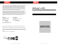
ONEAC ON Series is designed to provide power protection for various applications including telecommunication systems, information technology, retail information systems, computer-integrated manufacturing systems, semiconductor test equipment, and biomedical instrumentation and information systems.
ONEAC ON Series is designed to provide power protection for various applications including telecommunication systems, information technology, retail information systems, computer-integrated manufacturing systems, semiconductor test equipment, and biomedical instrumentation and information systems.


-
 1
1
-
 2
2
-
 3
3
-
 4
4
-
 5
5
-
 6
6
-
 7
7
-
 8
8
-
 9
9
-
 10
10
-
 11
11
-
 12
12
-
 13
13
-
 14
14
-
 15
15
-
 16
16
-
 17
17
-
 18
18
-
 19
19
-
 20
20
-
 21
21
-
 22
22
-
 23
23
-
 24
24
-
 25
25
-
 26
26
-
 27
27
-
 28
28
-
 29
29
-
 30
30
-
 31
31
-
 32
32


ONEAC ON Series User Instruction Manual
- Type
- User Instruction Manual
ONEAC ON Series is designed to provide power protection for various applications including telecommunication systems, information technology, retail information systems, computer-integrated manufacturing systems, semiconductor test equipment, and biomedical instrumentation and information systems.
Ask a question and I''ll find the answer in the document
Finding information in a document is now easier with AI
Related papers


Other documents
-
CyberPower RB12120X2A User manual
-
 Minute Man Entrust User manual
-
 Cables Direct UT-8801 Datasheet
-
CyberPower RB1270X3A User manual
-
CyberPower RB1270X4G User manual
-
-
ADTRAN Total Access 600 Owner's manual
-
Rackmount Solutions VA 700 User manual
-
Minute Man EN750 User manual
-
Toshiba ABTC1A-3M Datasheet

