Page is loading ...

XL MAINTENANCE MANUAL
ENGINE 01
CLUTCH 02
FUEL SYSTEM 03
EXHAUST SYSTEM 04
COOLING SYSTEM 05
ELECTRICAL SYSTEM 06
TRANSMISSION 07
PROPELLER SHAFT 09
FRONT AXLE 10
REAR AXLE 11
BRAKE AND AIR SYSTEM 12
WHEELS, HUBS AND TIRES 13
STEERING 14
SUSPENSION 16
BODY 18
HEATING AND A/C SYSTEMS 22
ACCESSORIES 23
LUBRICATION 24

XL MAINTENANCE MANUAL
SAFETY NOTICE
This maintenance manual has been prepared in
order to assist skilled mechanics in the efficient
repair and maintenance of PRÉVOST CAR - XL
VEHICLES.
This manual covers only the procedures as of
the manufacturing date.
Safety features may be impaired if other than
genuine PRÉVOST parts are installed.
Torque wrench tightening specifications must be
strictly observed. Locking devices must be in-
stalled or replaced by new ones, where speci-
fied. If the efficiency of a locking device is
impaired, It must be replaced.
This manual, or portions thereof, cannot be re-
produced in any form whatsoever, in whole or in
part, without the written consent of PRÉVOST
CAR INC..
The following words are used to emphasize par-
ticularly important information:
Warning: Identifies instructions which if not fol-
lowed, could result in serious personal injury or
loss of life.
Caution: Denotes instructions which if not fol-
lowed, could cause serious damage to vehicle
components.
Note: Indicates supplementary information
needed to fully understand and complete an in-
struction.
Although, the mere reading of such information
does not eliminate the hazard, your understand-
ing of the information will promote its correct use.
For your own safety and to ensure prolonged
service life of the vehicle, heed our Cautions,
Warnings and Notes; Ignoring them could result
in extensive damage and/or serious personal
injury.

1 - 1
SECTION 01: ENGINE
CONTENTS
1. ENGINE ..................................................................................................................................................... 1 - 3
1.1 Description................................................................................................................................... 1 - 3
2. ENGINE-MOUNTED COMPONENTS...................................................................................................... 1 - 3
2.1 Electronic Control Module......................................................................................................... 1 - 4
2.2 Electronic Unit Injector.............................................................................................................. 1 - 4
2.3 Synchronous Reference Sensor...............................................................................................1 - 5
2.4 Timing Reference Sensor......................................................................................................... 1 - 6
2.5 Turbo Boost Pressure Sensor .................................................................................................. 1 - 6
2.6 Coolant Temperature Sensor ................................................................................................... 1 - 6
2.7 Fuel Temperature Sensor......................................................................................................... 1 - 6
2.8 Air Temperature Sensor............................................................................................................ 1 - 7
2.9 Oil Pressure Sensor.................................................................................................................. 1 - 7
2.10 Oil Temperature Sensor............................................................................................................1 - 7
3. ENGINE-RELATED COMPONENTS........................................................................................................ 1 - 7
3.1 Coolant Level System (CLS)....................................................................................................... 1 - 8
3.2 Electronic Foot Pedal Assembly (EFPA) & Throttle Position Sensor ........................................ 1 - 8
3.3 Cruise Control Switch.................................................................................................................. 1 - 8
3.4 Diagnostic System Accessories.................................................................................................. 1 - 9
4. DDEC III Diagnostic Codes ..................................................................................................................... 1 - 10
4.1 Reading Diagnostic Codes - Flash Method............................................................................. 1 - 10
4.2 DDEC III Diagnostic Codes List............................................................................................... 1 - 11
5. ENGINE OIL LEVEL................................................................................................................................1 - 14
6. ENGINE OIL AND FILTER CHANGE..................................................................................................... 1 - 14
7. RECOMMENDED ENGINE OIL TYPE................................................................................................... 1 - 15
8. WELDING PRECAUTION....................................................................................................................... 1 - 15
9. POWER PLANT ASSEMBLY REMOVAL (Automatic and Manual)....................................................... 1 - 16
10. POWER PLANT ASSEMBLY INSTALLATION (Automatic and Manual).............................................. 1 - 19
11. ENGINE MOUNTS.................................................................................................................................1 - 19
12. JAKE BRAKE.......................................................................................................................................... 1 - 19
13. SPECIFICATIONS.................................................................................................................................. 1 - 20

Section 01: Engine
1 - 2
LIST OF ILLUSTRATIONS
FIG. 1: DETROIT DIESEL SERIES 60/50 ENGINES..................................................................................1 - 3
FIG. 2: ELECTRONIC CONTROL MODULE .............................................................................................. 1 - 4
FIG. 3: ELECTRONIC UNIT INJECTOR CROSS-SECTION ..................................................................... 1 - 5
FIG. 4: SRS LOCATION............................................................................................................................... 1 - 5
FIG. 5: BULL GEAR...................................................................................................................................... 1 - 5
FIG. 6: TIMING REFERENCE SENSOR AND RELATED PARTS............................................................. 1 - 6
FIG. 7: TURBO BOOST PRESSURE SENSOR .........................................................................................1 - 6
FIG. 8: ENGINE FUEL TEMPERATURE SENSOR.................................................................................... 1 - 7
FIG. 9: ENGINE OIL PRESSURE AND OIL TEMPERATURE SENSOR................................................... 1 - 7
FIG. 10: ELECTRONIC FOOT PEDAL ASSEMBLY.....................................................................................1 - 8
FIG. 11: DDL REMOTE CONNECTOR....................................................................................................... 1 - 10
FIG. 12: ENGINE OIL LEVEL DIPSTICK.....................................................................................................1 - 14
FIG. 13: OIL RESERVE TANK.................................................................................................................... 1 - 14
FIG. 14: ENGINE OIL DRAIN PLUG............................................................................................................ 1 - 15
FIG. 15: BELT TENSIONER CONTROL VALVE ........................................................................................ 1 - 16
FIG. 16: POWER PLANT ASSEMBLY REMOVAL .....................................................................................1 - 16
FIG. 17: ELECTRIC FAN CLUTCH CONNECTOR.....................................................................................1 - 17
FIG. 18: RUBBER DAMPER TOLERANCE ................................................................................................1 - 19
FIG. 19: POWER PLANT CRADLE INSTALLATION..................................................................................1 - 20

Section 01: Engine
1 - 3
1. ENGINE
1.1 Description
This vehicle may be powered by a 6-cylinder, four-cycle, Detroit Diesel Series 60 engine or a 4 cylinder, four
cycle, Detroit Diesel, Series 50 engine, both equipped with an electronic control system (DDEC III). Two
volumes of charge are used in the Series 60 engine: 11 liters or 12.7 liters, and one (8.5 liters) in the Series
50 engine. Summary information on the Electronic Control System is given in this section. Complete
maintenance and repair information on the engine will be found in the current DDEC III Service Manual
#6SE483. Engine controls, accessories and related components are covered in the applicable sections of
this maintenance manual. Engine removal and installation procedures are given at the end of this section.
The DDEC system is self-diagnostic, It can identify faulty components and other engine-related problems by
providing the technician with a diagnostic code. Refer to DDEC Troubleshooting Guide # 6SE492 for more
complete information on diagnosis of components and system problems published by Detroit Diesel.
DDEC III (Detroit Diesel Electronic Control) controls the timing and amount of fuel injection by the electronic
unit injectors (EUI). The system also monitors several engine functions using electrical sensors which send
electrical signals to the Electronic Control Module (ECM). The ECM computes the electrical signals and
determines the correct fuel output and timing for optimum power, fuel economy and emissions. The ECM
also has the ability to display warnings or shut down the engine completely (depending on option selection) in
the event of damaging engine conditions, such as low oil pressure, low coolant, or high oil temperature.
The system components are divided in two categories: engine-mounted components and engine-related
components.
2. ENGINE-MOUNTED COMPONENTS
FIGURE 1: DETROIT DIESEL SERIES 60 ENGINE 01015

Section 01: Engine
1 - 4
Engine-mounted components are as follows:
Electronic Control Module
Electronic Unit Injector
Synchronous Reference Sensor
Timing Reference Sensor
Turbo Boost Pressure Sensor
Coolant Temperature Sensor
Fuel Temperature Sensor
Air Temperature Sensor
Oil Pressure Sensor
Oil Temperature Sensor
2.1 Electronic Control
Module
The Electronic Control Module is mounted on the
starter side of the engine (Fig. 2). It is considered
the "Brain" of the DDEC III system because it
provides overall monitoring and control of the
engine by comparing input data from the various
sensors to a set of calibration data stored in the
EEPROM (Electrically Erasable, Programmable,
Read-Only Memory) within the Electronic Control
Module. After comparing the input data with the
calibrations data, the ECM sends high current
command pulses to the Electronic Unit Injectors
(EUI) to initiate fuel injection. The ECM also
receives feedback regarding the start and end of
injection for a given cylinder.
The EEPROM within the Electronic Control
Module is factory programmed by Detroit Diesel.
Reprogramming must be done at a Detroit Diesel
authorized service center. However, some
changes may be performed to the cruise control
and road speed limit using a diagnostic data
reader (see item #4 "DDEC III DIAGNOSTIC
CODES" in this section).
FIGURE 2: ELECTRONIC CONTROL MODULE (ECM)
01018
2.2 Electronic Unit Injector
The Electronic Unit Injector is a compact unit that
injects diesel fuel directly into the combustion
chamber (Fig. 3). The amount of fuel injected and
beginning of injection timing is determined by the
Electronic Control Module (ECM). The ECM
sends a command pulse which activates the
injector solenoid. The EUI performs four functions:
Creates the high-fuel pressure required for
efficient injection
Meters and injects the exact amount of fuel
required to handle the load
Atomizes the fuel for mixing with the air in the
combustion chamber
Permits continuous fuel flow for component
cooling

Section 01: Engine
1 - 5
01019
FIGURE 3: ELECTRONIC UNIT INJECTOR CROSS-SECTION
2.3 Synchronous Reference
Sensor
The Synchronous Reference Sensor (SRS) is an
electronic component that is mounted to the rear
of the gear case (Fig. 4). It extends through a hole
in the gear case and is positioned near the rear of
the bull gear. A bolt, inserted through a hole in the
SRS bracket, secures the SRS assembly to the
gear case. The SRS connector is black. The SRS
sends a signal to the ECM. This signal is
generated by a raised metal pin on the rear of the
bull gear (Fig. 5).
FIGURE 4: SRS LOCATION 01020
FIGURE 5: BULL GEAR 01021
The bull gear pin passes by the SRS as the
number one piston reaches 45before Top-Dead-
Center. This information is used by the ECM to
determine engine speed.
The SRS is non-serviceable and must be replaced
as a unit. No adjustment is required.

Section 01: Engine
1 - 6
2.4 Timing Reference Sensor
The Timing Reference Sensor (TRS) is an
electronic component that is mounted on the left
side of the gear case, near the crankshaft center
line (Fig. 6).
01022
FIGURE 6: TIMING REFERENCE SENSOR AND RELATED
PARTS
The TRS sensor extends through an opening in
the gear case and is positioned near the timing
wheel gear teeth. A bolt, inserted through a hole
in the TRS bracket, secures the TRS assembly to
the gear case. The TRS connector is Gray.
The TRS sensor sends a signal to the ECM. This
is generated by a series of evenly spaced teeth on
the timing wheel, rotating by the crankshaft. A
tooth passes by the TRS as each cylinder
reaches 10o before Top-Dead-Center. These
signals are used by the ECM to determine injector
solenoid operation time. The TRS is non-
serviceable and must be replaced as a unit. No
adjustment is required.
2.5 Turbo Boost Pressure
Sensor
The Turbo Boost Pressure Sensor is mounted to
the intake manifold with two bolts. A rubber O-ring
is used to seal the sensor to the manifold (Fig. 7).
This device is a pressure sensor that sends an
electrical signal to the ECM. The ECM uses this
information to compute the amount of air entering
the engine. Fuel supply is regulated by the turbo
boost sensor information to control engine
exhaust. The turbo boost sensor is non-
serviceable and must be replaced as an
assembly. No adjustment is required.
FIGURE 7: TURBO BOOST PRESSURE SENSOR 01023
2.6 Coolant Temperature
Sensor
The coolant temperature sensor is mounted on
the radiator side of the engine (Fig. 1). The sensor
protects the engine in case of overheating by
sensing coolant temperature.
2.7 Fuel Temperature Sensor
The Fuel Temperature Sensor (FTS) is installed
on the secondary fuel filter (Fig. 8). The FTS
sends an electrical signal to the ECM indicating

Section 01: Engine
1 - 7
fuel inlet temperature. The ECM uses this
information to calculate fuel consumption.
The FTS is non-serviceable and must be replaced
as a unit. No adjustment is required.
FIGURE 8: ENGINE FUEL TEMPERATURE SENSOR
01024
2.8 Air Temperature Sensor
The Air Temperature Sensor (Fig. 1) located on
the engine (starter side) near the intake manifold,
provides input data to vary hot idle speed and
injection timing. This helps to improve cold starts
and reduces white exhaust.
2.9 Oil Pressure Sensor
The Oil Pressure Sensor (OPS) is installed in the
main engine oil gallery. A typical location is the left
rear corner of the cylinder block (Fig. 9).
The OPS sends an electrical signal to the ECM
indicating the engine oil pressure at any given
speed. A low oil pressure signal exceeding seven
seconds is used by the ECM to begin the stop
engine or warning function. The OPS is non-
serviceable and must be replaced as a unit. No
adjustment is required.
01025
FIGURE 9: ENGINE OIL PRESSURE AND OIL
TEMPERATURE SENSOR
2.10 Oil Temperature Sensor
The Oil Temperature Sensor (OTS) is installed on
the main engine oil gallery. A typical location is the
left rear corner of the cylinder block as shown in
Figure 9. The OTS sends an electrical signal to
the ECM indicating engine oil temperature. The
ECM uses this information to modify engine speed
for better cold weather starts and faster warm-
ups. Oil temperatures exceeding engine
specifications for two seconds or more will
illuminate the "Check Engine" light. The OTS is
non-serviceable and must be replaced as a unit.
No adjustment is required.
3. ENGINE-RELATED
COMPONENTS
Engine-related components:
Coolant Level System (CLS)
Electronic Foot Pedal Assembly (EFPA) and
Throttle Position Sensor
Cruise Control Switch (CCS)
Diagnostic System Accessories (DSA)

Section 01: Engine
1 - 8
3.1 Coolant Level System
(CLS)
The coolant level system consists of a
conductivity probe mounted in the surge tank and
an electronic interface module located, inside the
rear junction box. Coolant level is determined by
the change in impedance of the probe and its
brass mount when it is immersed in coolant. The
electronic device in the module conditions the
signal to levels compatible with DDEC. Low
coolant level will trigger the warning engine
functions. The probe and the electronic interface
module are non-serviceable items and if found
defective, they should be replaced as units. No
adjustment is required.
3.2 Electronic Foot Pedal
Assembly (EFPA) &
Throttle Position Sensor
The Electronic Foot Pedal Assembly (EFPA)
connects the accelerator pedal to a Throttle
Position Sensor (TPS). The (TPS) is a device that
sends an electrical signal to the Electronic Control
Module (ECM) varying in voltage, depending on
how far down the pedal is depressed. The system
is installed in the space normally occupied by the
mechanical foot pedal. The (EFPA) has maximum
and minimum stops that are built into the unit
during manufacturing (Fig. 10).
The (TPS) converts the operator's foot pedal input
into a signal for the ECM. The (EFPA) is shown in
Figure 10.
When installed by the equipment manufacturer,
the TPS should not require adjustment. If the TPS
is suspected of being misadjusted, first check that
the sensor is installed in accordance with the
manufacturer's specifications. It is recommended
that the idle count be at 50 or higher with a full
throttle count of up to 200.
The TPS is self-calibrating and therefore has no
optimum closed throttle or wide open throttle
count value. If the counts are within the 50 to 200
range, the sensor is properly set.
FIGURE 10: ELECTRONIC FOOT PEDAL ASSEMBLY 01026
Monitor the (TPS) as the controls move it through
its full stroke. Be sure there is no misalignment or
obstruction preventing the smooth movement of
the TPS through the full stroke. Using a diagnostic
data reader, check that the idle and full throttle
position counts do not fall within the error zones.
The error zones occur when the idle position is
less than 14 counts, or when the full throttle
position is more than 233 counts. Should these
conditions occur, the ECU will signal diagnostic
codes of 21-12 for idle error and 21-23 for wide
open throttle error.
3.3 Cruise Control Switches
(CCS)
The four cruise control switches are located in the
driver's area on the L.H. side control panel.
1. Cruise On/Off: This is the main switch that
actuates the ECM memory in order to use the
speed regulating mode.
2. Cruise Set: This switch is used to set the
cruise control speed or to decrease the set speed
by 2 MPH at each application.

Section 01: Engine
1 - 9
Note: Cruise control system will not accept
speed settings, nor will the "Resume" switch
operate below 20 mph (32 km/h) and the
engine speed must be above 1100 RPM.
3. Cruise Resume: Each time this switch is
actuated, the speed will be increased by 2 mph
(3,5 km/h). This switch allows the driver to return
to the last regulated speed following a brake or
"DECEL" switch application.
Note: On-off switch must be in the "ON"
position in order to return to the last regulated
speed.
4. Cruise Decel: Will cancel the cruise
temporarily like a brake application but without
actuating brake light. Set speed is still in memory
for resume.
For additional information, see your "Operator's
Manual".
3.4 Diagnostic System
Accessories (DSA)
The DDEC III engine Diagnostic System
Accessories include the following:
"Check Engine" warning light;
"Stop Engine" warning light;
"Stop Engine Override" switch; and
Diagnostic Data Link (DDL) connectors.
1. "Check Engine" Warning Light: This
light, mounted on the central dashboard
panel, illuminates to indicate that a
problem is currently being detected and
that a code has been stored in the ECM
memory. This light also has a 5-second
bulb check when the ignition is first turned
on. The Check Engine Light illuminates
when the temperature at coolant sensors
reaches 217F (103C) and the
temperature at oil sensors reaches 239°F
(115°C). In extremely hot weather and
high altitude, the coolant temperature can
reach 215F (102C) and more when
climbing a long grade at full throttle. If this
situation occurs, the "Check engine" light
will come on (at 217F - 103C) and the
engine overtemperature protection
system (EOP) will be activated. If the
cooling system is properly maintained, the
temperature should stabilize below the
shut back temperature of 222F (106C)
so the vehicle can operate normally.
Note: Engine is not considered
"overheating" when below 215
F (102
C).
2. "Stop Engine" Warning Light: This
light, also mounted on the central
dashboard panel, illuminates to indicate
that a major engine problem is occurring
(with the exception of a 5-second bulb
check when the ignition is first turned on).
The Stop Engine Light illuminates when
temperature at coolant sensors reaches
222°F (106°C) and the temperature at oil
sensors reaches 260°F (127°C). When
sensors reach those temperatures, the
engine will shut down after 30 seconds.
This 30-second delay period may be
repeated using the "Stop Engine
Override" switch.
Note: Once engine is stopped, it can not be
restarted until the malfunction is corrected.
3. "Stop Engine Override" Switch: This
switch, mounted on the L.H. lower switch
panel, is used when the "Stop Engine"
warning light is illuminated. Push down
rocker switch to reset the 30 second
delay period and the shutdown
procedure. This switch can be repeatedly
depressed, i.e. one (1) pulse is
sufficient for each 30 second period,
for engine power in an emergency
situation.
Note: The "Stop Engine Override" switch will
be operative only if it has been depressed
before the end of the 30 second delay period.
Caution: The "Stop Engine Override" must
be used only in emergency situations to bring
vehicle to a safe stop. Excessive use of this
switch could cause serious damage to the
engine.

Section 01: Engine
1 - 10
4. Diagnostic Data Link (DDL)
Connectors: The driver's side connector
is located at rear of L.H. side control
panel on XL Coaches and on L.H. lateral
console on XL Shells; the remote
connector is located in steering
compartment (Fig. 11). They are used to
connect the Diagnostic Data Reader
(DDR) for reading codes or to access
pertinent data on the engine condition.
This enables a more complete analysis of
any defect found in the DDEC system
operation. For more information, see
"Detroit Diesel Troubleshooting Guide
#6SE492".
FIGURE 11: DDL REMOTE CONNECTOR
07005B
4. DDEC III DIAGNOSTIC
CODES
4.1 Reading Diagnostic
Codes - Flash Method:
DDEC III makes use of two types of codes; active
and inactive. The difference between the two are
as follows:
1.Active Codes: These are the codes which
are currently keeping the "Check Engine" or
"Stop Engine" light illuminated. Active codes
are flashed via the "Stop Engine" warning
light when checked with the "Stop Engine
Override" switch.
2.Inactive Codes: These are all the codes
logged in the ECM (whether or not they are
currently turning "ON" the "Stop Engine" or
"Check Engine" lights). Inactive codes are
flashed via the "Check Engine" warning light
when checked with the "Stop Engine
Override" switch.
In most instances, only the DDR can provide the
information necessary for a quick diagnosis of a
problem. However, if you do not have a DDR
available, the following procedure will let you "read
out" codes. Make sure the starter selector switch
(located on rear junction box in engine
compartment) is in the normal position.
Momentarily depress the "Stop Engine Override"
switch with the ignition "ON" and the engine idling
or not running. Active codes will be flashed on the
"Stop Engine" warning light, followed by the
inactive codes being flashed on the "Check
Engine" warning light. The cycle repeats itself until
the operator depresses the "Stop Engine
Override" switch i.e.: A code "43" consists of four
flashes, followed by a short pause, then three
flashes in quick succession.

Section 01: Engine
1 - 11
4.2 DDEC III Diagnostic Codes List
DDC Code
Number
(Flashed) Description DDC Code
Number
(Flashed) Description
11 Variable speed governor sensor
voltage low 12 Variable speed governor sensor
voltage high
13 Coolant level circuit failed low 14 Intercooler temperature circuit
failed high
14 Coolant temperature circuit failed
high 14 Oil temperature circuit failed high
15 Intercooler temperature failed low 15 Coolant temperature circuit failed
low
15 Oil temperature circuit failed low 16 Coolant level circuit failed high
17 Bypass position circuit failed high 18 Bypass position circuit failed low
21 EFPA circuit failed low 22 EFPA circuit failed low
23 Fuel temperature circuit failed high 24 Fuel temperature circuit failed low
25 Reserved for "no codes" 26 Aux. shutdown #1 active
26 Aux. shutdown #2 active 27 Air temperature circuit failed high
28 Air temperature circuit failed low 31 Aux. output #3 open circuit (high
side)
31 Aux. output #3 short to ground
(high side) 31 Aux. output #4 open circuit (high
side)
31 Aux. output #4 short to ground
(high side) 32 SEL open circuit
32 SEL short to battery 33 Turbo boost pressure circuit failed
high
34 Turbo boost pressure circuit failed
low 35 Oil pressure circuit failed high
36 Oil pressure circuit failed high 37 Fuel pressure circuit failed high

Section 01: Engine
1 - 12
DDC Code
Number
(Flashed) Description DDC Code
Number
(Flashed) Description
38 Fuel pressure circuit failed low 41 Too many SRS (missing TRS)
42 Too few SRS (missing SRS) 43 Coolant level low
44 Intercooler temperature high 44 Coolant temperature high
44 Oil temperature high 45 Oil pressure low
46 Battery voltage low 47 Fuel pressure high
48 Fuel pressure low 52 A/D conversion fail
53 Nonvolatile checksum incorrect 53 EEPROM write error
54 Vehicle speed sensor fault 55 J1939 data link fault
55 Proprietary link fault (master) 55 Proprietary link fault (receiver)
56 J1587 data link fault 57 J1922 data link fault
58 Torque overload 61 Response time long
62 Aux. output #1 short to battery 62 Aux. output #1 open circuit
62 Aux. output #2 short to battery 62 Aux. output #2 open circuit
62 Aux. output #5 short to battery 62 Aux. output #5 open circuit
62 Aux. output #6 short to battery 62 Aux. output #6 open circuit
62 Aux. output #7 short to battery 62 Aux. output #7 open circuit
62 Aux. output #8 short to battery 62 Aux. output #8 open circuit
63 PWM #1 short to battery 63 PWM #1 open circuit
63 PWM #2 short to battery 63 PWM #2 open circuit
63 PWM #3 short to battery 63 PWM #3 open circuit
63 PWM #4 short to battery 63 PWM #4 open circuit
64 Turbo speed circuit failed 65 Reserved for air filter differential
pressure circuit failed high
65 Reserved for air filter differential
pressure circuit failed low 66 Reserved for oil filter differential
pressure circuit failed high

Section 01: Engine
1 - 13
DDC Code
Number
(Flashed) Description DDC Code
Number
(Flashed) Description
66 Reserved for oil filter differential
pressure circuit failed low 67 Coolant pressure circuit failed
high
67 Coolant pressure circuit failed low 68 Idle validation circuit fault
(grounded circuit)
68 Idle validation circuit fault (open
circuit) 71 Injector response time short
72 Vehicle overspeed 72 Reserved for vehicle overspeed
(absolute)
73 Reserved for air differential
pressure high 74 Oil differential pressure high
75 Battery voltage high 76 Engine overspeed with engine
brake
77 All other faults not listed 81 Timing actuator (dual fuel) failed
high
81 Oil level circuit failed high 81 Crankcase pressure circuit failed
high
82 Timing actuator (dual fuel) failed
low 82 Oil level circuit failed low
82 Crankcase pressure circuit failed
low 83 Oil level high
83 Crankcase pressure high 84 Oil level low
84 Crankcase pressure low 85 Engine overspeed
86 Pump pressure circuit failed high 86 Barometric pressure circuit failed
high
87 Pump pressure circuit failed low 87 Barometric pressure circuit failed
high
88 Coolant pressure low -- CEL short to battery
-- CEL open circuit -- Clock Module failure
-- Clock module abnormal rate

Section 01: Engine
1 - 14
5. ENGINE OIL LEVEL
Check the oil level daily with the engine stopped. If
the engine has just been stopped and is warm,
wait at least 10 minutes to allow the oil to drain
back to the oil pan before checking. Wipe the
dipstick clean, then check oil level. The level
should always be within the safe range on the
dipstick (Fig. 12) . Add the proper grade of oil to
maintain the correct level on the dipstick. All diesel
engines are designed to consume some oil, so a
periodic addition of oil is normal.
Warning: Touching a hot engine can cause
serious burns.
Caution: Do not overfill. Oil may be blown
out through the crankcase breather if the
crankcase is overfilled.
Caution: Clean end of tube before removing
the dipstick to prevent oil contamination.
FIGURE 12: ENGINE OIL LEVEL DIPSTICK 01027
Caution: If the oil level is constantly above
normal and excess lube oil has not been
added to the crankcase, consult with an
authorized Detroit Diesel service outlet for the
cause. Fuel or coolant dilution of lube oil can
result in serious engine damage.
The vehicle is provided with an oil reserve tank in
the engine compartment. To adjust oil level, open
the tank drain valve and allow oil to discharge into
the engine until it reaches the "Full" mark on the
dipstick, then close the valve. Check reserve tank
oil level through the level sight tube on the side of
the tank and top-up if necessary (Fig. 13).
FIGURE 13: OIL RESERVE TANK 01033
6. ENGINE OIL AND FILTER
CHANGE
Both the oil and filter should be changed every
12,500 miles (20 000 km) or once a year,
whichever comes first. However, more frequent
changes may be required when the engine is
subject to high level of contamination and/or
overheating. Change intervals may be decreased
or gradually increased with experience on specific
lubricants until the most practical service condition
has been established. Always refer to the lubricant
manufacturer's recommendations (analysis of
drained oil can be helpful).
Caution: Do not use solvent to dilute the
engine oil when draining oil. Dilution of the
fresh oil can occur which may be detrimental
to the engine.
Change engine oil with the vehicle on a flat and
level surface and with the parking brake applied. It
is best to drain the oil when the engine is still
warm.
1. From under the vehicle, remove the
engine drain plug on the oil pan. Allow oil
to drain (Fig. 14).
Warning: Hot engine oil can cause serious
burns. Wear coveralls with sleeves pulled
down and gloves to protect hands.

Section 01: Engine
1 - 15
2. Reinstall the drain plug.
FIGURE 14: ENGINE OIL DRAIN PLUG 01029
3. Remove the spin-on filter cartridge using
a 1/2" drive socket wrench and extension.
4. Dispose of the used oil and filter in an
environmentally responsible manner in
accordance with state and/or federal
(EPA) recommendations.
5. Clean the filter adapter with a clean rag.
6. Lightly coat the filter gasket (seal) with
clean engine oil.
7. Install the new filter on the adapter and
tighten manually until the gasket touches
the mounting adapter head. Tighten full-
flow filters an additional two-thirds of a
turn manually. Then, tighten bypass filter
one full turn manually.
Caution: Overtightening may distort or crack
the filter adapter.
8. Remove the engine oil filler cap and pour
oil in the engine until it reaches the
"FULL" mark on the dipstick (Fig. 13).
9. Start and run the engine for a short period
and check for leaks. After any leaks have
been corrected, stop the engine long
enough for oil from various parts of the
engine to drain back to the crankcase
(approximately 20 minutes).
Add oil as required to bring the level
within the safe range on the dipstick (Fig.
12).
7. RECOMMENDED ENGINE
OIL TYPE
To provide maximum engine life, lubricants should
meet the following specifications:
SAE Viscosity Grade: 15W-40
API Classification: CG-4
HT/HS Viscosity: 3.7 cP minimum
Note: Monograde oils should not be used in
these engines regardless of API Service
Classification.
Note: The use of supplemental oil additives
are discouraged from use in Detroit Diesel
Engines.
Synthetic oils
Synthetic oils may be used in Detroit Diesel
engines provided they are API licensed and meet
the performance and chemical requirements of
non-synthetic oils outlined previously. Synthetic
oils do not permit extension of recommended oil
drain intervals.
Lubricant Selection World Wide
Oils meeting API CD or CC specifications may be
used if they also meet military specification MIL-L-
2104 E or F. Oil which meets European CCMC D4
specifications may also be used. Modification of
drain intervals may be necessary, depending on
fuel quality. Contact Detroit Diesel Corporation for
further guidance.
8. WELDING PRECAUTION
Caution: Precautions must be taken to
prevent damage to the DDEC electronic
control system when welding. Disconnect
battery power, ground cables and the 6-pin
power connector at the ECM (Electronic
Control Module) before welding. Failure to
isolate the DDEC system from high current
flow can result in severe ECM damage.

Section 01: Engine
1 - 16
9. POWER PLANT
ASSEMBLY REMOVAL
(AUTO. / MAN. TRANS.)
To access the engine or engine-related
components, the vehicle power plant assembly
must be removed as a whole unit by means of a
slide-out cradle. The power plant assembly
includes the engine, transmission (including
retarder if so equipped), air compressor, alternator
and transmission oil cooler.
Remove the power plant assembly as follows:
Caution: Tag hoses and cables before
disconnecting in order to facilitate
reinstallation. Plug all openings to prevent
dirt from entering the system.
Note: No parts within the ECM are
serviceable. If found defective, replace the
complete ECM unit.
1. Disconnect the battery or batteries from
the starting system by removing one or
both of the battery cables from each
battery system. With the electrical circuit
disrupted, accidental contact with the
starter button will not produce an engine
start. In addition, the Electronic Unit
Injectors (EUI) will be disabled,
preventing any fuel delivery to the injector
tips.
Warning: Due to the heavy load of the rear
bumper assembly, it must be adequately
supported before attempting to remove it.
2. Remove the rear bumper assembly from
the vehicle. Refer to Section 18, "BODY",
under heading "Rear Bumper Removal
and Installation".
3. Drain the engine cooling system. Refer to
Section 05, "COOLING" under heading
"Draining Cooling System".
FIGURE 15: BELT TENSIONER CONTROL VALVE
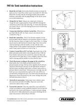
12018
4. Locate the belt tensioner control valve (4,
Figs. 15 & 16). Turn handle counter-
clockwise in order to reverse pressure in
belt tensioner air bellows and release
tension on belts. Remove belts.
5. Exhaust all air from the air system. (if
necessary, refer to Section 12, "BRAKES
& AIR SYSTEM").
FIGURE 16: POWER PLANT ASSEMBLY REMOVAL
01014B
6. Disconnect and remove the engine air
intake duct mounted between air cleaner
housing and turbocharger inlet (3, Fig.
16).
Caution: To avoid damage to turbocharger,
cover the turbocharger inlet opening to
prevent foreign material from entering.

Section 01: Engine
1 - 17
7. Disconnect and remove the air intake
duct mounted between the air cooler
outlet and the intake engine (2, Fig. 16).
FIGURE 17: ELECTRIC FAN CLUTCH CONNECTOR
01031
8. Disconnect and remove the section of
coolant pipe assembly mounted between
the radiator outlet and the water pump
inlet (1, Fig. 16).
9. Disconnect the coolant delivery hose
located inside of engine close to the water
pump.
10. Disconnect the electric fan clutch
connector located next to water pump (1,
Fig. 17).
11. Dismantle the air bellow from the upper
bracket tensioner for the fan drive
assembly. Remove the upper bracket (7,
Fig. 16).
12. If necessary, remove the fan drive system
from the engine compartment by
removing the four retaining bolts, washers
and nuts securing the fan drive to the
radiator floor.
13. Disconnect and remove the air intake
duct mounted between the turbocharger
outlet and the air cooler inlet.
14. Disconnect two vent hoses from the
thermostat housing and from the coolant
pipe assembly.
15. Disconnect and remove the section of
coolant pipe assembly mounted between
the thermostat housings and the radiator
inlet.
16. Disconnect and remove the small hose
connected from the heater line valve to
the water pump.
17. Disconnect the small heater hose located
on the cylinder head at the back of the
engine.
18. Disconnect temperature sensor for the
pyrometer located above the exhaust
pipe, close to the turbocharger (optional).
19. Disconnect and remove the exhaust pipe
mounted between the turbocharger outlet
and the exhaust bellows. If necessary,
refer to Section 4, under heading
"Exhaust System".
Caution: To avoid damage to turbocharger,
cover the turbocharger outlet opening to
prevent foreign material from entering.
20. Disconnect the block heater connector
above the power steering pump (R.H.
side).
21. Disconnect the steel-braided air line from
the A/C compressor air bellows.
22. Disconnect the engine oil pressure steel-
braided hose from the mechanical oil
pressure gauge and the cable of the
gauge water temperature (5 & 6, Fig. 16).
23. Disconnect the oil delivery hose from the
valve located at the reserve tank exit.
24. Disconnect the power steering pump
supply and discharge hoses. Cap hose
openings immediately to limit fluid loss.
Remove retaining clips from cradle.

Section 01: Engine
1 - 18
25. Close engine fuel supply shutoff valve on
primary fuel filter. Disconnect the fuel line
connected to the inlet port. On vehicles
equipped with the optional water
separator fuel filter, disconnect the
connector and remove cable ties from
cradle.
26. Disconnect the air compressor discharge,
governor steel-braided air lines and the
manual filling air lines from compressor.
Remove retaining clips.
27. Disconnect the hose connecting the
compressor head to the septic reservoir.
28. Disconnect ground cables from rear
subframe ground stud, located close to
the starting motor.
29. Disconnect positive cable (red terminal)
from starting motor solenoid.
30. Disconnect the power plant wiring
harness main connectors from EMC and
remove retaining clips from engine
compartment back wall.
31. On vehicles equipped with an automatic
transmission with output retarder,
disconnect steel-braided air line from
pressure regulator output. On XL-40 &
45E vehicles, the pressure regulator is
mounted on the curb side rear wheel
housing, inside the engine compartment.
On XL-45 vehicles, the regulator is
mounted inside R.H. side rear service
compartment (rear L.H. corner).
32. Disconnect fuel return line from bulkhead
fixed on engine cylinder head end.
33. On vehicles equipped with an electrically
operated cold starting aid, disconnect the
delivery hose from the starting aid
cylinder solenoid valve. Remove cable
ties securing hoses.
34. Disconnect turbo boost pressure gauge
air line (if vehicle is so equipped) from
engine air intake.
35. (Only if vehicle is equipped with an output
retarder). Remove the transmission
rubber damper assembly above
transmission by removing: nut, bushing,
rubber damper, rubber damper guide, bolt
and washer. Remove the rubber damper
bracket from transmission
36. Disconnect connectors from transmission
- On left side: four at rear and one close
to yoke - On right side: close to output
retarder's solenoid valve.
37. From under the vehicle, disconnect the
propeller shaft as detailed in Section 09
"PROPELLER SHAFT".
Manual Transmission:
Disconnect gear shift linkage.
Remove clutch slave cylinder from
transmission without disconnecting the
hydraulic hose.
38. Inspect the power plant assembly to
ensure that nothing will interfere when
sliding out the cradle.
39. Remove the six retaining bolts, washers
and nuts securing the power plant cradle
to the vehicle rear subframe (Fig. 19).
Note: Check if any spacer(s) have been
installed between power plant cradle and
vehicle rear subframe, and if so, note position
of each washer for reinstallation purposes.
40. Using a forklift, with a minimum capacity
of 4,000 lbs (1 800 kg), slightly raise the
power plant cradle. Pull engine out slowly
from the engine compartment. Make sure
all lines, wiring and controls are
disconnected and are not tangled.
Caution: Due to the minimum clearance
between the power plant equipment and the
top of the engine compartment, extreme care
should be used to raise the power plant
cradle, just enough to free the cradle.
Clearance between power plant cradle and
mounting rail should range between 1/4" and
1/2" (6-12 mm).
/