
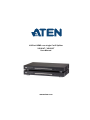
4/8-Port HDMI over single Cat 5 Splitter
VS1814T / VS1818T
User Manual
www.aten.com

VS1814T / VS1818T User Manual
ii
FCC Information
FEDERAL COMMUNICATIONS COMMISSION INTERFERENCE
STATEMENT
This equipment has been tested and found to comply with the limits for a Class A digital
device, pursuant to Part 15 of the FCC Rules. These limits are designed to provide reasonable
protection against harmful interference when the equipment is operated in a commercial
environment. This equipment generates, uses, and can radiate radio frequency energy and, if
not installed and used in accordance with the instruction manual, may cause harmful
interference to radio communications. Operation of this equipment in a residential area is
likely to cause harmful interference in which case the user will be required to correct the
interference at his own expense.
FCC Caution: Any changes or modifications not expressly approved by the party
responsible for compliance could void the user's authority to operate this equipment.
CE Warning:
This is a class A product. In a domestic environment this product may cause radio
interference in which case the user may be required to take adequate measures.
RoHS
This product is RoHS compliant.
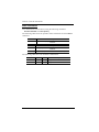
SJ/T 11364-2006
The following contains information that relates to China.

VS1814T / VS1818T User Manual
iii
User Information
Online Registration
Be sure to register your product at our online support center:
Telephone Support
For telephone support, call this number:
User Notice
All information, documentation, and specifications contained in this manual
are subject to change without prior notification by the manufacturer. The
manufacturer makes no representations or warranties, either expressed or
implied, with respect to the contents hereof and specifically disclaims any
warranties as to merchantability or fitness for any particular purpose. Any of
the manufacturer's software described in this manual is sold or licensed as is.
Should the programs prove defective following their purchase, the buyer (and
not the manufacturer, its distributor, or its dealer), assumes the entire cost of all
necessary servicing, repair and any incidental or consequential damages
resulting from any defect in the software.
The manufacturer of this system is not responsible for any radio and/or TV
interference caused by unauthorized modifications to this device. It is the
responsibility of the user to correct such interference.
The manufacturer is not responsible for any damage incurred in the operation
of this system if the correct operational voltage setting was not selected prior
to operation. PLEASE VERIFY THAT THE VOLTAGE SETTING IS
CORRECT BEFORE USE.
International http://eservice.aten.com
International 886-2-8692-6959
China 86-10-5255-0110
Japan 81-3-5615-5811
Korea 82-2-467-6789
North America 1-888-999-ATEN ext 4988
United Kingdom 44-8-4481-58923

VS1814T / VS1818T User Manual
iv
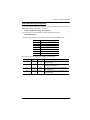
Package Contents
The VS1814T / VS1818T 4/8-Port HDMI over single Cat 5 Splitter package
consists of:
1 VS1814T / VS1818T 4/8-Port HDMI over single Cat 5 Splitter
1Power Cord
1 Mounting Kit
1 User Instructions*
Check to make sure that all the components are present and that nothing got
damaged in shipping. If you encounter a problem, contact your dealer.
Read this manual thoroughly and follow the installation and operation
procedures carefully to prevent any damage to the unit, and/or any of the
devices connected to it.
*Features may have been added to the VS1814T / VS1818T since this manual
was printed. Please visit our website to download the most up-to-date
version.
© Copyright 2014 ATEN® International Co., Ltd.
Manual Date: 2014-10-16
ATEN and the ATEN logo are registered trademarks of ATEN International Co., Ltd. All rights reserved.
All other brand names and trademarks are the registered property of their respective owners.

VS1814T / VS1818T User Manual
v
Contents
FCC Information . . . . . . . . . . . . . . . . . . . . . . . . . . . . . . . . . . . . . . . . . . . . . ii
RoHS. . . . . . . . . . . . . . . . . . . . . . . . . . . . . . . . . . . . . . . . . . . . . . . . . . . . . . ii
SJ/T 11364-2006. . . . . . . . . . . . . . . . . . . . . . . . . . . . . . . . . . . . . . . . . . . . . ii
User Information . . . . . . . . . . . . . . . . . . . . . . . . . . . . . . . . . . . . . . . . . . . . .iii
Online Registration . . . . . . . . . . . . . . . . . . . . . . . . . . . . . . . . . . . . . . . .iii
Telephone Support . . . . . . . . . . . . . . . . . . . . . . . . . . . . . . . . . . . . . . . .iii
User Notice . . . . . . . . . . . . . . . . . . . . . . . . . . . . . . . . . . . . . . . . . . . . . .iii
Package Contents. . . . . . . . . . . . . . . . . . . . . . . . . . . . . . . . . . . . . . . . . . . iv
Contents . . . . . . . . . . . . . . . . . . . . . . . . . . . . . . . . . . . . . . . . . . . . . . . . . . . v
About this Manual . . . . . . . . . . . . . . . . . . . . . . . . . . . . . . . . . . . . . . . . . . . vii
Conventions . . . . . . . . . . . . . . . . . . . . . . . . . . . . . . . . . . . . . . . . . . . . . . .viii
Product Information. . . . . . . . . . . . . . . . . . . . . . . . . . . . . . . . . . . . . . . . . .viii
1. Introduction
Overview . . . . . . . . . . . . . . . . . . . . . . . . . . . . . . . . . . . . . . . . . . . . . . . . . . .1
Features . . . . . . . . . . . . . . . . . . . . . . . . . . . . . . . . . . . . . . . . . . . . . . . . . . .2
Requirements . . . . . . . . . . . . . . . . . . . . . . . . . . . . . . . . . . . . . . . . . . . . . . . 3
Source Device . . . . . . . . . . . . . . . . . . . . . . . . . . . . . . . . . . . . . . . . . . . . 3
Receiving Device. . . . . . . . . . . . . . . . . . . . . . . . . . . . . . . . . . . . . . . . . . 3
Cables . . . . . . . . . . . . . . . . . . . . . . . . . . . . . . . . . . . . . . . . . . . . . . . . . .3
Components . . . . . . . . . . . . . . . . . . . . . . . . . . . . . . . . . . . . . . . . . . . . . . . . 4
Front View . . . . . . . . . . . . . . . . . . . . . . . . . . . . . . . . . . . . . . . . . . . . . .4
Rear View . . . . . . . . . . . . . . . . . . . . . . . . . . . . . . . . . . . . . . . . . . . . . . .5
2. Hardware Setup
Rack Mounting . . . . . . . . . . . . . . . . . . . . . . . . . . . . . . . . . . . . . . . . . . . . . . 7
Grounding . . . . . . . . . . . . . . . . . . . . . . . . . . . . . . . . . . . . . . . . . . . . . . . . . . 9
Installation. . . . . . . . . . . . . . . . . . . . . . . . . . . . . . . . . . . . . . . . . . . . . . . . . 10
3. Operation
Overview . . . . . . . . . . . . . . . . . . . . . . . . . . . . . . . . . . . . . . . . . . . . . . . . . . 11
EDID Learn Pushbutton . . . . . . . . . . . . . . . . . . . . . . . . . . . . . . . . . . . . . . 11
EDID Mode Selection . . . . . . . . . . . . . . . . . . . . . . . . . . . . . . . . . . . . . . . . 12
Installing the RS-232 Controller . . . . . . . . . . . . . . . . . . . . . . . . . . . . . . . . 12
4. RS-232 Commands
Overview . . . . . . . . . . . . . . . . . . . . . . . . . . . . . . . . . . . . . . . . . . . . . . . . . . 13
RS-232 Serial Interface. . . . . . . . . . . . . . . . . . . . . . . . . . . . . . . . . . . . . . . 13
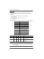
Configuring the Serial Port . . . . . . . . . . . . . . . . . . . . . . . . . . . . . . . . . 13
Switch Port . . . . . . . . . . . . . . . . . . . . . . . . . . . . . . . . . . . . . . . . . . . . . 14
CEC Commands . . . . . . . . . . . . . . . . . . . . . . . . . . . . . . . . . . . . . . . . . 15
Read Commands . . . . . . . . . . . . . . . . . . . . . . . . . . . . . . . . . . . . . . . . 16
Baud Rate Setting Commands . . . . . . . . . . . . . . . . . . . . . . . . . . . . . . 17
Reset Commands . . . . . . . . . . . . . . . . . . . . . . . . . . . . . . . . . . . . . . . .18
Verification. . . . . . . . . . . . . . . . . . . . . . . . . . . . . . . . . . . . . . . . . . . . . .18

VS1814T / VS1818T User Manual
vi
Appendix
Safety Instructions . . . . . . . . . . . . . . . . . . . . . . . . . . . . . . . . . . . . . . . . . . 19
General . . . . . . . . . . . . . . . . . . . . . . . . . . . . . . . . . . . . . . . . . . . . . . . . 19
Rack Mounting . . . . . . . . . . . . . . . . . . . . . . . . . . . . . . . . . . . . . . . . . . 21
Technical Support. . . . . . . . . . . . . . . . . . . . . . . . . . . . . . . . . . . . . . . . . . . 22
International . . . . . . . . . . . . . . . . . . . . . . . . . . . . . . . . . . . . . . . . . . . . 22
North America . . . . . . . . . . . . . . . . . . . . . . . . . . . . . . . . . . . . . . . . . . . 22
Specifications . . . . . . . . . . . . . . . . . . . . . . . . . . . . . . . . . . . . . . . . . . . . . . 23
Limited Warranty. . . . . . . . . . . . . . . . . . . . . . . . . . . . . . . . . . . . . . . . . . . . 24

VS1814T / VS1818T User Manual
vii
About this Manual
This User Manual is provided to help you get the most from your VS1814T /
VS1818T system. It covers all aspects of installation, configuration and
operation. An overview of the information found in the manual is provided
below.
Introduction, introduces you to the VS1814T / VS1818T system. Its
purpose, features and benefits are presented, and its front and back panel
components are described.
Hardware Setup, describes how to set up your VS1814T / VS1818T
installation. The necessary steps are provided.
Operation, explains the fundamental concepts involved in operating the
VS1814T / VS1818T through the RS-232 serial interface.
An Appendix, provides specifications and other technical information
regarding the VS1814T / VS1818T.

VS1814T / VS1818T User Manual
viii
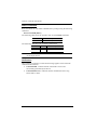
Conventions
This manual uses the following conventions:
Product Information
For information about all ATEN products and how they can help you connect
without limits, visit ATEN on the Web or contact an ATEN Authorized
Reseller. Visit ATEN on the Web for a list of locations and telephone numbers:
Monospaced Indicates text that you should key in.
[ ] Indicates keys you should press. For example, [Enter] means to
press the Enter key. If keys need to be chorded, they appear
together in the same bracket with a plus sign between them:
[Ctrl+Alt].
1. Numbered lists represent procedures with sequential steps.
♦Bullet lists provide information, but do not involve sequential steps.
→Indicates selecting the option (on a menu or dialog box, for
example), that comes next. For example, Start → Run means to
open the Start menu, and then select Run.
Indicates critical information.
International http://www.aten.com
North America http://www.aten-usa.com

1
Chapter 1
Introduction
Overview
The ATEN VS1814T / VS1818T 4/8-Port HDMI over single Cat 5 Splitter is
a fast and efficient way of switching digital high definition video from one
input source to 4/8 displays located up to 100m away. It implements HDBaseT
extension technology to connect the VS1814T / VS1818T to receiver units
over one single Cat 5e cable in order to transmit rich HDMI multimedia content
in real time.
You can connect up to 4 (VS1814T) or 8 (VS1818T) HDMI Receivers (such
as VE812R) to a unit. The built-in RS-232 port on the VS1814T / VS1818T
rear panel allows connected units to be controlled through a high-end controller
or PC.
The VS1814T / VS1818T supports up to 4k2k HDTV resolution, as well as up
to 1920 x 1200 PC resolution. It is equipped with an EDID selection method,
providing constant and reliable EDID data for the HDMI source device to
efficiently optimize video resolution.
The VS1814T / VS1818T HDMI Splitter is HDCP (High Bandwidth Digital
Content Protection) compliant and compatible with a wide range of ATEN
devices (switches, matrix, converters, and so on). It supports all HDMI-
enabled equipment, such as DVD players, satellite set-top boxes and all HDMI
displays, making it an effective solution in broadcasting applications, digital
signage and educational settings.

VS1814T / VS1818T User Manual
2
Features
One HDMI input to 4/8 HDMI outputs via a Cat 5e cable
Offers local HDMI output
Extends displays up to 100 m
Anti-jamming – resists signal interference during high-quality video
transmissions using HDBaseT technology
Implements HDBaseT extension technology using only one Cat 5 cable to
connect the transmitter and receiver
HDMI (3D, Deep color, 4kx2k); HDCP Compatible
Supports Dolby True HD and DTS HD Master Audio
Consumer Electronics Control (CEC) support
Built-in bi-directional RS-232 serial remote port for high-end system
control*
Supports resolutions of up to Ultra HD 4kx2k and 1080p Full HD
Supports up to 340MHz bandwidth for high performance video
Signaling rates up to 3.4 Gbits
EDID mode selection
Rack-mountable
*The VS1814T / VS1818T AP operation instructions can be downloaded
from the ATEN website (www.aten.com).

Chapter 1. Introduction
3
Requirements
The following equipment is required for a complete VS1814T / VS1818T
installation:
Source Device
The following equipment must be installed on any source of HDMI content:
HDMI output connector
Receiving Device
A local display device with an HDMI input connector
An HDMI Receiver (such as VE812R) with an RJ-45 port for each output
port you will be installing
Cables
Standard HDMI cables for the source device and local display device
Cat 5e cables for the HDMI Receivers
Note: 1. No cables are included in this package. We strongly recommend that
you purchase high-quality cables of appropriate lengths since this will
affect the quality of the audio and video display. Contact your dealer
to purchase the correct cable sets.
2. A DVI/HDMI adapter is required when connecting to a DVI source
or display device. If a DVI/HDMI adapter is used. audio is not
supported.
3. If you wish to utilize the VS1814T / VS1818T’s high-end serial
controller function, you will also need to purchase an appropriate RS-
232 cable. See Installing the RS-232 Controller, page 12.

VS1814T / VS1818T User Manual
4
Components
Front View
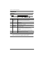
Note: The VS1818T’s front panel is shown on this page. It is similar to the
front panel of VS1814T except for the number of HDBaseT Out port
LEDs – the VS1814T has 4 HDBaseT Out port LEDs.
No. Component Description
1 HDBaseT Out
port LEDs (1~4 /
1~8)
Lights to indicate there is a working connection to the HDMI
receiving device(s) connected to the port(s).
2 HDMI Out LED Lights to indicate there is a working connection to the local
display device.
3 HDMI In LED Lights to indicate that there is a working connection to the
source device (i.e., computer).
4 EDID Learn
Pushbutton
Press and release this button to automatically learn the
active display’s EDID.
5 EDID Learn LED Flashes green to indicate that EDID Learning Mode is in
progress (see EDID Learn Pushbutton, page 11).
Lights green to indicate that EDID learning process is
successful.
Lights red to indicate that EDID learning process failed.
6 Power LED Lights green to indicate that the VS1814T / VS1818T is
receiving power and is up and running.
14
2 3 56

Chapter 1. Introduction
5
Rear View
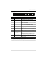
Note: The VS1818T’s rear panel is shown on this page. It is similar to the rear
panel of VS1814T except for the number of HDBaseT Out ports – the
VS1814T has 4 HDBaseT Out ports.
No. Component Function
1Power Socket This is a standard 3-pin AC power socket. The
power cord from an AC source plugs in here.
2Power Switch This is a standard rocker switch that powers the unit
on and off.
3Grounding Terminal The grounding wire attaches here. See Grounding,
page 9, for further details.
4EDID Mode Switch Press this button to cycle through the EDID settings
stored in the unit (see EDID Mode Selection,
page 12).
5HDBaseT Out ports
(1~4 / 1~8)
The Cat 5e cables that connects the HDMI Receiver
Units plug in here.
6HDMI Input port The cable from your HDMI source device plugs in
here.
7HDMI Output port The cable from your HDMI display device plugs in
here.
8Firmware
Upgrade button
This button is for enabling the Firmware Upgrade
Mode.
Note: Contact your product provider for details on
upgrading the firmware of your device.
7RS-232 Serial Port This is the serial remote port for output source
selection and high-end system control, including
firmware upgrade.
1 2 5963 478

VS1814T / VS1818T User Manual
6
This Page Intentionally Left Blank

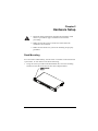
7
Chapter 2
Hardware Setup
Rack Mounting
For convenience and flexibility, the VS1814T / VS1818T can be mounted on
system racks. To rack mount a unit do the following:
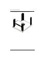
1. Using the screws provided in the Rack Mount Kit, screw the mounting
bracket into the side of the unit as show in the diagram below:
1. Important safety information regarding the placement of this
device is provided on page 19. Please review it before
proceeding.
2. Make sure that the power to all devices connected to the
installation are turned off.
3. Make sure that all devices you will be installing are properly
grounded.
Phillips hex headPhillips hex head
M3 x 6M3 x 6

VS1814T / VS1818T User Manual
8
2. Screw the bracket into any convenient location on the rack.

Chapter 2. Hardware Setup
9
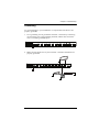
Grounding
To prevent damage to your installation, it is important that all devices are
properly grounded.
1. Use a grounding wire to ground the VS1814T / VS1818T by connecting
one end of the wire to the grounding terminal, and the other end of the
wire to a suitable grounded object.
2. Make sure that all devices in your VS1814T / VS1818T installation are
properly grounded.

VS1814T / VS1818T User Manual
10
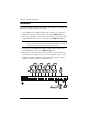
Installation
Refer to the installation diagram (the numbers in the diagram correspond to the
numbers of the steps) and do the following:
1. Use an HDMI Type A Male-to-Male cable to connect your computer or
HDMI source device to the VS1814T / VS1818T’s HDMI Input port.
2. Use up to 4 (VS1814T) / 8 (VS1818T) Cat 5e cables to connect up to four
/ eight HDMI Receiver units (i.e. VE812R) to the HDBaseT Out ports.
Note: The HDMI Receiver unit’s HDMI OUT port connects to the HDMI
IN port on your video display device using an HDMI cable. Refer to
your receiving device’s User Manual for more details.
3. (Optional) Use an HDMI Type A Male-to-Male cable to connect your
local HDMI display device to the HDMI Output port.
4. Plug the power cord that came with the VS1814T / VS1818T into an AC
power source, then plug the power cable into the splitter’s power socket
5. (Optional) To edit the VS1814T / VS1818T system settings, connect a
hardware / software controller to the RS-232 port.
1
3
4
2
5

11
Chapter 3
Operation
Overview
The VS1814T / VS1818T offers easy and flexible EDID learning and mode
selection through pushbuttons located in the unit’s front and rear panels.
EDID Learn Pushbutton
The VS1814T / VS1818T can automatically learn a display’s EDID by
pressing the EDID Learn Pushbutton located on the front panel. Follow these
steps:
1. Attach the video display/monitor that you want to use to the VS1814T /
VS1818T HDMI Output port (See Installation, page 10).
2. To learn the EDID configuration of the video display/monitor, press and
release the EDID Learn Pushbutton.
3. The EDID Learn LED flashes to indicate that the settings are being
captured, then lights steady to indicate that EDID learning process is
successful.
Note: The EDID Learn LED lights red to indicate that EDID learning process
failed.

VS1814T / VS1818T User Manual
12
EDID Mode Selection
The VS1814T / VS1818T offers an easy and flexible EDID Mode selection
method using the rear panel EDID Mode Switch.
Extended Display Identification Data (EDID) is a data format that contains a
display's basic information and is used to communicate with the video source/
system.
Simply press the EDID Mode pushbutton to toggle between the Default and
other EDID Settings (0~7), as follows:
0 (Default) – EDID is set to the ATEN default configuration
1 (Port 1) – Implements the EDID of the connected display to Port 1, and
passes it to the video source
2 (Auto) - Implements the EDID of all connected displays. The VS1814T
/ VS1818T uses the best resolution for all displays
3 (Learn) - Uses the EDID configuration acquired from the EDID
Learning process.
4 ~ 7- Reserved.
You can also select the EDID Mode using RS-232 commands. See RS-232
Commands, page 13 for details.
Installing the RS-232 Controller
In order to use the RS-232 serial interface to attach a high-end controller (such
as a PC) to the VS1814T / VS1818T, use a serial cable such as a modem cable.
The end connecting to the VS1814T / VS1818T should have a 9-pin male
connector. Connect this to the serial interface on the rear of the VS1814T /
VS1818T.
See RS-232 Commands, page 13 for details.
Page is loading ...
Page is loading ...
Page is loading ...
Page is loading ...
Page is loading ...
Page is loading ...
Page is loading ...
Page is loading ...
Page is loading ...
Page is loading ...
Page is loading ...
Page is loading ...
-
 1
1
-
 2
2
-
 3
3
-
 4
4
-
 5
5
-
 6
6
-
 7
7
-
 8
8
-
 9
9
-
 10
10
-
 11
11
-
 12
12
-
 13
13
-
 14
14
-
 15
15
-
 16
16
-
 17
17
-
 18
18
-
 19
19
-
 20
20
-
 21
21
-
 22
22
-
 23
23
-
 24
24
-
 25
25
-
 26
26
-
 27
27
-
 28
28
-
 29
29
-
 30
30
-
 31
31
-
 32
32


