WOLFPACK 3636-Chassis Modular Matrix Switcher WEB GUI User manual
- Type
- User manual
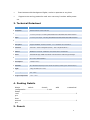
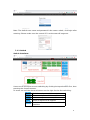
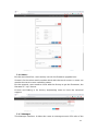
WOLFPACK 3636-Chassis Modular Matrix Switcher WEB GUI is a powerful modular matrix switcher with 9 input slots and 9 output slots, supporting up to 36 inputs and 36 outputs. It offers mixed signal inputs and outputs, including DVI, HDMI, HDBaseT, Fiber Optic, and 3G-SDI, providing versatile connectivity options for various applications. With uncompressed signal transmission, high switching speed (12.5Gbps per channel), and a powerful processing core, it ensures high-fidelity image output and reliable performance.
WOLFPACK 3636-Chassis Modular Matrix Switcher WEB GUI is a powerful modular matrix switcher with 9 input slots and 9 output slots, supporting up to 36 inputs and 36 outputs. It offers mixed signal inputs and outputs, including DVI, HDMI, HDBaseT, Fiber Optic, and 3G-SDI, providing versatile connectivity options for various applications. With uncompressed signal transmission, high switching speed (12.5Gbps per channel), and a powerful processing core, it ensures high-fidelity image output and reliable performance.


-
 1
1
-
 2
2
-
 3
3
-
 4
4
-
 5
5
-
 6
6
-
 7
7
-
 8
8
-
 9
9
-
 10
10
-
 11
11
-
 12
12
-
 13
13
-
 14
14
-
 15
15
-
 16
16
-
 17
17
-
 18
18


WOLFPACK 3636-Chassis Modular Matrix Switcher WEB GUI User manual
- Type
- User manual
WOLFPACK 3636-Chassis Modular Matrix Switcher WEB GUI is a powerful modular matrix switcher with 9 input slots and 9 output slots, supporting up to 36 inputs and 36 outputs. It offers mixed signal inputs and outputs, including DVI, HDMI, HDBaseT, Fiber Optic, and 3G-SDI, providing versatile connectivity options for various applications. With uncompressed signal transmission, high switching speed (12.5Gbps per channel), and a powerful processing core, it ensures high-fidelity image output and reliable performance.
Ask a question and I''ll find the answer in the document
Finding information in a document is now easier with AI

Other documents
-
ANGUSTOS AMVC-0909 User manual
-
BeingHD FIX-MANAGER-400-E User manual
-
KanexPro FLEX-MMX16 User manual
-
PTN FMX12 User manual
-
KanexPro FLEX-MMX32 User manual
-
RTI VFX-124 User manual
-
PureLink Media Axis Matrix Switchers User manual
-
DVDO Modular User manual
-
ATEN VM6809H User manual
-
KanexPro HDMMX3232-4K User manual