

MSBV Installation Instructions
2
DISCLAIMER
Milestone AV Technologies, and its affiliated corporations and
subsidiaries (collectively, “Milestone”), intend to make this
manual accurate and complete. However, Milestone makes no
claim that the information contained herein covers all details,
conditions or variations, nor does it provide for every possible
contingency in connection with the installation or use of this
product. The information contained in this document is subject
to change without notice or obligation of any kind. Milestone
makes no representation of warranty, expressed or implied,
regarding the information contained herein. Milestone assumes
no responsibility for accuracy, completeness or sufficiency of
the information contained in this document.
®Chief is a registered trademark of Milestone AV Technologies.
All rights reserved.
IMPORTANT SAFETY INSTRUCTIONS!
WARNING: A WARNING alerts you to the possibility of
serious injury or death if you do not follow the instructions.
CAUTION: A CAUTION alerts you to the possibility of
damage or destruction of equipment if you do not follow the
corresponding instructions.
WARNING: Failure to read, thoroughly understand, and
follow all instructions can result in serious personal injury,
damage to equipment, or voiding of factory warranty! It is the
installer’s responsibility to make sure all components are
properly assembled and installed using the instructions
provided.
WARNING: Failure to provide adequate structural strength
for this component can result in serious personal injury or
damage to equipment! It is the installer’s responsibility to
make sure the structure to which this component is attached
can support five times the combined weight of all equipment.
Reinforce the structure as required before installing the
component.
WARNING:
Exceeding the weight capacity can result in
serious personal injury or damage to equipment! It is the
installer’s responsibility to make sure the combined weight of
all components attached to the MSBV does not exceed 125 lbs
(56.7 kg).
WARNING: Use this mounting system only for its intended
use as described in these instructions. Do not use
attachments not recommended by the manufacturer.
WARNING: Never operate this mounting system if it is
damaged. Return the mounting system to a service center for
examination and repair.
WARNING: Do not use this product outdoors.
NOTE: The MSBV interface bracket is compatible with the
following VESA patterns:
•100 x 100mm
• 200 x 100mm
• 200 x 200mm
• 300 x 100mm
• 300 x 200mm
• 400 x 200mm
IMPORTANT ! : The MSBV interface brackets are designed
to be mounted to a:
•Listed Chief MCD6000 dual ceiling mount;
•Listed Chief MCS6000 single ceiling mount.
--SAVE THESE INSTRUCTIONS--

Installation Instructions MSBV
3
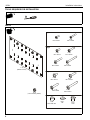
DIMENSIONS
LEGEND
MOUNTING BUTTONS FIT INTO
TEARDROP SLOTS ON MOUNT
300x200
400x200
0.380.75
1.97
0.75
0.38
100x100
200x100
300x100
0.31
0.81
WITH SPACERS
200x200 MOUNTING PATTERNS USE
BUTTONS ATTACHED DIRECTLY TO
THE BACK OF THE DISPLAY
17.00
9.63
0.20
DIMENSIONS: INCHES
Tighten Fastener
Apretar elemento de fijación
Befestigungsteil festziehen
Apertar fixador
Serrare il fissaggio
Bevestiging vastdraaien
Serrez les fixations
Loosen Fastener
Aflojar elemento de fijación
Befestigungsteil lösen
Desapertar fixador
Allentare il fissaggio
Bevestiging losdraaien
Desserrez les fixations
Phillips Screwdriver
Destornillador Phillips
Kreuzschlitzschraubendreher
Chave de fendas Phillips
Cacciavite a stella
Kruiskopschroevendraaier
Tournevis à pointe cruciforme

MSBV Installation Instructions
4
TOOLS REQUIRED FOR INSTALLATION
PARTS
Bag A
Bag B
Bag C
Bag D
A (8)
M4 x 12mm B (8)
M4 x 25mm
C (8)
M5 x 12mm D (8)
M5 x 25mm
E (8)
M5 x 30mm F (8)
M5 x 45mm
G (8)
M6 x 12mm H (8)
M6 x 25mm
J (8)
M6 x 30mm K (8)
M6 x 45mm
L (8)
.750x.344x.500 M (4)
M4 N (4)
7mm
P (1)
[MSBV bracket]
Q (4)
[.242 mounting button]

Installation Instructions MSBV
5
Guidelines for Using Spacers (if required)
If the display has a recessed mounting surface, protrusions or a
power box, a spacer must be placed between the display and
MSBV bracket (A) and longer mounting hardware must be
used. (See Figure 1)
Figure 1
IMPORTANT ! : Proceed to the correct procedure for
installation of MSBV based upon the display’s mounting
pattern.
INSTALLATION
WARNING: IMPROPER INSTALLATION CAN LEAD TO
DISPLAY FALLING CAUSING SERIOUS PERSONAL
INJURY OR DAMAGE TO EQUIPMENT! Using screws of
improper size may damage your display. Properly sized
screws will easily and completely thread into display
mounting holes. If spacers are required, be sure to use longer
screws of the same diameter.
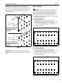
100 x 100mm Pattern
1. Select four properly sized M4 screws from Bag A.
2. Attach the MSBV bracket (A) using the hole pattern on back
of display and holes noted at "X". (See Figure 2)
3. To prevent equipment damage, do not over-tighten the
screws into the display.
Figure 2
200 x 100mm Pattern
1. Select six properly sized M4 screws from Bag A.
2. Attach the MSBV bracket (A) using the hole pattern on back
of display and holes noted at "X". (See Figure 3)
3. To prevent equipment damage, do not over-tighten the
screws into the display.
Figure 3
Attaching to display with
protrusions, recessed
mounting surface, or a
power box.
(L)
Attaching to display with
NO protrusions, recessed
mounting surface, nor a
power box.
Long screw from
Bags A, B or C
Short screw from
Bags A or B
(A)
X
X
X
X
Attach MSBV using fasteners at "X"
X
X
X
X
Attach MSBV using fasteners at "X"
X
X

MSBV Installation Instructions
6
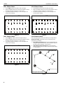
300 x 100mm Pattern
1. Select eight properly sized M4 screws from Bag A.
2. Attach the MSBV bracket (A) using the hole pattern on back
of display and holes noted at "X". (See Figure )
3. To prevent equipment damage, do not over-tighten the
screws into the display.
Figure 4
300 x 200mm Pattern
1. Select eight M5 or M6 screws from Bag B or Bag C.
2. Attach the MSBV bracket (A) using the hole pattern on back
of display and holes noted at "X". (See Figure 5)
3. To prevent equipment damage, do not over-tighten the
screws into the display.
Figure 5
400 x 200mm Pattern
1. Select six M5 or M6 screws from Bag B or Bag C.
2. Attach the MSBV bracket (A) using the hole pattern on back
of display and holes noted at "X". (See Figure 6)
3. To prevent equipment damage, do not over-tighten the
screws into the display.
Figure 6
200 x 200mm Pattern
Select the appropriate method for attaching mounting buttons
directly to display, dependent on size of mounting screw
required for your display.
1. If mounting screw is M4, attach four mounting buttons (Q)
using four shoulder washers (N), four M4 washers (M) and
four M4 screws from Bag A. (See Figure 7)
2. If mounting screw is M5 or M6, attach four mounting
buttons (Q) using four M5 or M6 screws from Bag B or Bag
C. (See Figure 7)
Figure 7
X
X
X
X
Attach MSBV using fasteners at "X"
X
X
X
X
X
X
X
X
Attach MSBV using fasteners at "X"
X
X
X
X
X
X
X
X
Attach MSBV using fasteners at "X"
X
X
(Q)
(N)
(M)
(B)
(D, E, F, H, J or K)
If using M4 screws
If using M5 or M6 screws

Installation Instructions MSBV
7
3. If 200 x 200mm hole pattern is shifted high on the screen,
attach the MSBV bracket (A) vertically with four M5 or M6
screws (Bag B or Bag C). (See Figure 8)
Figure 8
INSTALLING DISPLAY TO MOUNT
1. Install display to UL Listed Chief mount following
instructions included with the mount.
Attach MSBV using fasteners at
"X"
X
XX
X

USA/International A 6436 City West Parkway, Eden Prairie, MN 55344
P800.582.6480 / 952.225.6000
F877.894.6918 / 952.894.6918
Europe A Franklinstraat 14, 6003 DK Weert, Netherlands
P+31 (0) 495 580 852
F+31 (0) 495 580 845
Asia Pacific A Office No. 918 on 9/F, Shatin Galleria
18-24 Shan Mei Street
Fotan, Shatin, Hong Kong
P852 2145 4099
F852 2145 4477
MSBV Installation Instructions
Chief, a products division of
Milestone AV Technologies
8800-002592 Rev02
2014 Milestone AV Technologies
www.chiefmfg.com
05/14
-
 1
1
-
 2
2
-
 3
3
-
 4
4
-
 5
5
-
 6
6
-
 7
7
-
 8
8


Chief MIWRFVB Installation guide
- Category
- Wall & ceiling mounts accessories
- Type
- Installation guide
Ask a question and I''ll find the answer in the document
Finding information in a document is now easier with AI
Related papers
-
Chief PSB2243 Installation guide
-
Chief FHB5028 Installation guide
-
-
-
-
-
-
-
-