Page is loading ...

17, Bharat Industrial Estate, T. J. Road, Sewree (W),
Mumbai-400015. INDIA
Sales Direct: (022)24156638 Tel.:(022) 2412 4540, 2418 1649
Fax: 2414 9659 E-mail : [email protected],
Website : www.kusamelectrical.com; www.kusam-meco.co.in
LIST OF PRODUCTS
* Digital Multimeter * Digital AC & AC/DC Clampmeter
* AC Clamp Adaptor * AC/DC Current Adaptor
* Thermo Anemometer * Thermo Hygrometer
* Distance Meter * Digital Lux Meter
* Network Cable Tester * Power Factor Regulator
* Earth Resistance Tester * Digital Panel Meters
* DC Power Supplies * High Voltage Detector
* Calibrators * Gas Analysers
* Frequency Counter * Function Generator
* Phasing Sticks * Battery Tester
* Waterproof Pen Testers * Solar Power Meter
* EMF Detector
* Wood, Paper & Grain Moisture Meter
* Transistorised Electronic Analog & Digital Insulation
Resistance Testers(upto 10 KV)
* Digital Sound Level Meter & Sound Level Calibrator
* Digital contact & Non-contact Type Tachometer
* Digital Non-contact (infrared) Thermometer
* Maximum Demand Controller/Digital Power Meter
* Digital Hand Held Temperature Indicators
AN ISO 9001:2008 COMPANY
MODEL
KM 061 / KM 062
OPERATION MANUAL

Nearly every electrical engineer has a hand held digital clamp meter
(Tongtester). We sometimes take them for granted, until we damage them
or “burn them out”. If you incorrectly connect your clamp meter to a circuit,
or if you have the clamp meter on wrong setting, you damage the meter
and possibly hurt yourself. You can also get into trouble if you try to
measure the voltage across a charged capacitor.
Clamp meter users frequently burn their meters by trying to measure
current the same way as they measure voltage. Remember, you measure
voltage across a circuit, and current through a circuit. When you use the
current input, your clamp meter becomes a low impedance circuit element.
Even if you correctly insert your clamp meter in to the circuit, you can
still damage your meter. Don’t try to measure current in excess of your
meter’s capacity. Check the current capacity of the Clamp meter.
If you are measuring current in industrial environment to prevent
excess current from flowing through your meter, always disconnect your
test leads from the circuit under test whenever you change Clamp meter
functions. Set your meter to the correct function, say current, and its
highest range for the setting. If the reading is small, change the range to
the next lower range till the reading can be read with the best possible
accuracy. When measuring voltage, connect the test leads before your
apply power to your circuit. To be safe, start by setting your meter to its
highest range first.
TAKE MEASUREMENT CAREFULLY AND YOU’LL SPARE YOUR
METER AND YOURSELF, SOME PAIN
Safety .......................................................................................01
Terms in this Manual ................................................................02
Electrical Symbols ...................................................................03
General Specifications .............................................................04
Electrical Specifications ..........................................................06
Product Discription ...................................................................10
Operation ..................................................................................11
Maintenance ............................................................................ 17
Cleaning & Storage ..................................................................18
Battery Replacement ...............................................................18
Test Certificate .........................................................................19
Warranty ..................................................................................20

-1-
SAFETY
This manual contains information & warnings that must be followed
for operating the instrument safely and maintaining the instrument in a
safe operating condition. If the instrument is used in a manner not
specified by the manufacturer, the protection provided by the
instrument may be impaired.
The meter protection rating, against the users, is double insulation per
IEC61010-1 2nd Ed., EN61010-1 2nd Ed., UL61010-1 2nd Ed., CAN /
CSA C22.2 No. 61010-1, 2nd Ed., IEC61010-2-032, EN61010-2-032,
UL61010B-2-032 & CAN / CSA C22.2 N0.61010-2-032-04 :
Category CAT III 600V AC & DC.
-2-
To reduce the risk of fire or electric shock, do not
expose this product to rain or moisture. The meter is
intended only for indoor use.
To avoid electrical shock hazard, observe the proper safety
precautions when working with voltages above 60 VDC
or 30 VAC rms. These voltage levels pose a potential shock
hazard to the user.

7
7
-3-
2006/95/EC and Electromagnetic compatibility directive 2004/108/EC
-4-
Average sensing (KM 061)
True RMS sensing (KM 062)
Safety : Meets IEC61010-1 2nd Ed., EN61010-1
2nd Ed., UL61010-1 2nd Ed., CAN/CSA
C22.2 No. 61010.1-0.92, IEC61010-2-032,
EN61010-2-032 & UL61010B-2-032 &
CAN/CSA C22.2 No. 61010-2-032-04:
Category III 600 Volts AC & DC.
Transient Protection : 6.5kV (1.2/50mS surge)
Pollution degree : 2

-5-
E.M.C. : Meets EN61326-1:2006 (EN55022,
EN61000-3-2, EN61000-3-3, EN61000-4-2,
EN61000-4-3, EN61000-4-4, EN61000-4-5,
EN61000-4-6, EN61000-4-8, EN61000-4-11)
In anRF field of 3V/m :
Capacitance function is not specified
Other function ranges : Total Accuracy = Specified Accuracy + 50digits
Performance above 3V/m is not specified
Overload Protections :
Clamp-on jaws : DC/AC 400A rms continuous
+ & COM terminals (all functions) : 600V DC / VAC rms
Power Supply : Standard 1.5V AAA size Alkaline battery x 2.
Power Consumption : 11mA typical for ACA / DCA & 2.9 mA typical
for other functions.
APO Timing : Idle for 30 minutes
APO Consumption : typical 10mA (KM 061) & 190mA (KM062)
Dimension : 188(L) x 63(W) x 40(H) mm
Weight : 218gm approx.
Jaw opening & Conductor diameter : 30mm max.
Accessories : Test lead pair, batteries installed,
User’s Manual, Carrying case,
-6-
DC Voltage
Range Resolution Accuracy
400.0 mV
4.000 V
40.00 V
400.0 V
600 V
±(0.3%rdg + 3dgts)
±(0.5%rdg + 3dgts)
±(1.0%rdg + 4dgts)
Input Impedance : 10MW, 30pF nominal (1000MW for 400.0mV range)
AC Voltage
Range Resolution Accuracy
4.000 V
40.00 V
400.0 V
±(1.0%rdg + 4dgts)
50Hz ~ 60Hz
Input Impedance : 10MW, 30pF nominal
Crest Factor : <2:1 at full scale & <4:1 at half scale (Model KM062 only)
For KM062, ACV & ACA Clamp-on accuracies are specified from 5% to
100% of range or otherwise specified.
60Hz ~ 500Hz
4.000 V
40.00 V
400.0 V
±(1.5%rdg + 4dgts)
50Hz ~ 500Hz
600 V ±(2.0%rdg + 4dgts)
100 mV
1 mV
10 mV
100 mV
1 V
1 mV
10 mV
100 mV
1 mV
10 mV
100 mV
1 V

-7-
Resistance (Ohms)
Range Resolution Accuracy
400.0 W
4.000 kW
40.00 kW
400.0 kW
4.000 MW
±(0.8%rdg + 6dgts)
±(0.6%rdg + 4dgts)
±(1.0%rdg + 4dgts)
Open Circuit Voltage : 0.4V DC typical
40.00 MW±(2.0%rdg + 4dgts)
Audible Continuity Tester
Open Circuit Voltage : 0.4V DC typical
Range : 400.0W; Accuracy : 1.5% + 8d
Audible threshold : between 10W & 120W.
Diode Tester
Open Circuit Voltage : < 1.6V DC typical
Test Current : 0.4mA typical
Capacitance
1)
Range Resolution 2) 3)
Accuracy
500.0 nF
5.000mF
50.00 mF
500.0mF
3000 mF
±(3.5%rdg + 6dgts)
1) Additional 50.00nF range accuracy is not specified
2) Accuracies with film capacitor or better
3) Specified with battery voltage above 2.8V (approx. Half full battery).
Accuracy decreases gradually to 12% at low battery warning voltage
of approx. 2.4V
100 mW
1 W
10 W
100 W
1 KW
10 KW
100 pF
1 nF
10 nF
100 nF
1 mF
-8-
DCA Current (Clamp-on)
Range Resolution 1) 2)
Accuracy
400.0 A
0A ~ 50.0A
50.0A ~ 200.0A
200.0A ~ 300.0A
300.0A ~ 400.0A
±(1.5%rdg + 5dgts)
±(2.5%rdg + 5dgts)
1) Induced error from adjacent current-carrying conductor : <0.01A/A
2) Relative Zero mode is applied to offset the non-zero residual
readings, if any
r
±(1.0%rdg + 4dgts)
±(2.0%rdg + 5dgts)
ACA Current (Clamp-on)
Range
400.0 A
40Hz ~ 60Hz @ 0 ~ 50A
1) Induced error from adjacent current-carrying conductor : <0.01A/A
Crest Factor : < 1.8:1 at full scale & < 3.6:1 at half scale
(Model KM 062 only)
60Hz ~ 400Hz @ 0 ~ 50A
40Hz ~ 60Hz @ 50A ~ 200A
60Hz ~ 200Hz @ 50A ~ 200A
40Hz ~ 60Hz @ 200A ~ 300A
40Hz ~ 60Hz @ 300A ~ 400A
1)
Accuracy
±(1.5%rdg + 5dgts)
±(2.0%rdg + 5dgts)
±(1.0%rdg + 6dgts)
±(1.5%rdg + 5dgts)
±(2.0%rdg + 5dgts)
±(2.5%rdg + 5dgts)
100 mA
100 mA
100 mA
100 mA

-9-
Hz Frequency
Function
Display Counts : 5000
Maximum resolution : 0.001Hz
Accuracy : 0.5% + 4d
400.0 mV
4.000 V
40.00 V
400.0 V
Sensitivity (Sine wave) Range
5Hz ~ 20kHz
5Hz ~ 100kHz
10Hz ~ 1kHz
5Hz ~ 100kHz
5Hz ~ 5kHz
600 V
350 mV
3.2 V
25 V
100 V
410 V
DCA / ACA Unspecified
-10-
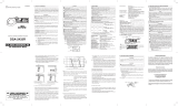
3) PRODUCT DESCRIPTION
Note : Top of the line model is used as representative for illustration
purposes.
1. Hall-effect Clamp Jaw for
AC & DC Current
magnetic field pick up
2. Hand/Finger Barrier to
indicate the limits of safe
access of the meter during
measurement.
3. Push-buttons for special
functions & features
4. Input jack for all functions
EXCEPT non-invasive
ACA & DCA current
functions
5. Common (Ground
reference) input Jack for
all functions EXCEPT non-
invasive ACA & DCA
current functions.
6. Slide-switch Selector to
turn the power ON/OFF
and Select a function.
7. 3¾ digits 4000 counts
LCD display
8. Jaw trigger for opening
the clamp jaw
9. DCA direction for + polarity
as well as Jawcenter
indicator, at where best
ACA & DCA accuracy is
specified.

-12-
Note : DC 400.0mV range is designed with 1000MW high input
impedance for least current drain in measuring small signals, and can
cope better with most commercially available voltage output
transducers / adapters. The non-zero display reading is normal when
the meter inputs are open circuit, which will not affect actual
measurement accuracy. The meter will show close-to-zero readings
when the inputs are shorted. Open input is actually a floating
condition, which is not a zero-volt-input condition.
Press the Hz button momentarily to activate Hz Frequency. The Hz
trigger Level is determined by the selected function-range from
where the Hz function is activated. In ACV function, activating the
Hz function during significant measurements can get the most
appropriate trigger level to avoid electrical noises in most cases.
Electrical noise may cause unstable Hz readings . Activating the Hz
function at AC 4.000V range (before making significant measurements)
can get lower trigger level (higher sensitivity). Hz reading may show
zero when the sensitivity is insufficient.
Set slide-switch to Voltage function position. Inputs are made through
the test leads terminals.
-11-
DC Voltage, AC Voltage, Hz Frequency Functions
CAUTION : Before and after hazardous voltage measurements, test
the Voltage function on a known source such as line
voltage to determine proper meter functioning.
4) OPERATION

-13-
CAUTION (Application and removal of the Clamp-on meter)
Press the jaw trigger and clamp the jaws around only one single
conductor of a circuit for load current measurement. Make sure the
jaws are completely closed, or else it will introduce measurement
errors. Enclosing more than one conductor of a circuit will result in
differential current measurement (like identifying leakage current).
Locate the conductor(s) at the Jaws center as much as possible to get
the best measuring accuracy. The jaw “+” mark indicates current flow
direction on DCA positive readings.
For removal, press the jaw trigger and remove the jaws from the
conductor(s).
Inputs are made through the clamp jaws for non-invasive ACA &
DCA current measurements.
ACA & DCA Current Clamp-on function
-14-
Note : In DCA measurements, hysteresis of the jaws (after measuring
high DC currents) may introduce non-zero residual readings. Relative
Zero mode should be used each time to offset the residual readings,
if any, for more accurate measurements.
r
Adjacent current-carrying devices such as transformers, motors &
conductor wires will affect measurement accuracy. Keep the jaws away
from them as much as possible to minimize influence.

-15-
ON
ON
Select
Inputs are made through the test leads terminals. Slide-switch ON
defaults at W. Press SELECT button momentarily 3 times to select
Capacitance function.
Relative zero mode can be used to zero out the parasitic
capacitance of the leads and the internal protection circuitry of the meter
when measuring low capacitance in the order of Pico Farad (pf).
r
-16-
Display Backlight (KM 062 only)
Press the SELECT button for 1 second or more to toggle the display
backlight on and off.
The Annunciator “ ” turns on. The meter also enters manual ranging
mode where available. The annunciator “ ” turns off.AUTO
The max feature compares and displays the measured maximum
value as fast as 30ms with auto-ranging capability. It allows the
meter to capture INRUSH currents in current functions. Press and hold
the MAX button for 1 second or more to toggle to the max feature.
The annunciators “MAX” and “ ” turn on.
H
H
The Hold feature freezes the display for later viewing. Press the
HOLD button momentarily to toggle to the Hold feature. The
annunciator “ ” turns on.
H
H
When the meter is on, the Auto Power Off (APO) feature will switch the
meter into a sleep mode automatically to extend battery life after
approximately 30 minutes of no slide-switch nor push button operations
to extend battery life. To wake up the meter from APO, press any push
button momentarily or set the slide-switch to the OFF position and then
slide back on again. Always set the slide-switch to the OFF position
manually when the meter is not in use.


ISO 9001
REGISTERED
QC
PASS
KUSAM-MECO
MUMBAI
TEST CERTIFICATE
DIGITAL CLAMPMETER +
MULTIMETER
This Test Certificate warrantees that the product has been
inspected and tested in accordance with the published
specifications.
The instrument has been calibrated by using equipment
which has already been calibrated to standards traceable
to national standards.
MODEL NO. KM 061 / KM 062
SERIAL NO. ___________
DATE: ___________
-19-
WARRANTY
Each “KUSAM-MECO” product is warranted to be free from defects in
material and workmanship under normal use & service. The warranty
period is one year (12 months) and begins from the date of despatch of
goods. In case any defect occurs in functioning of the instrument, under
proper use, within the warranty period, the same will be rectified by us
free of charges, provided the to and fro freight charges are borne by you.
This warranty extends only to the original buyer or end-user customer of a
“KUSAM-MECO” authorized dealer.
This warranty does not apply for damaged Ic’s, fuses, burnt PCB's,
disposable batteries, carrying case, test leads, or to any product which in
“KUSAM-MECO’s” opinion, has been misused, altered, neglected,
contaminated or damaged by accident or abnormal conditions of
operation or handling.
“KUSAM-MECO” authorized dealer shall extend this warranty on new and
unused products to end-user customers only but have no authority to
extend a greater or different warranty on behalf of “KUSAM-MECO”.
“KUSAM-MECO’s” warranty obligation is limited, at option, free of charge
repair, or replacement of a defective product which is returned to a
“KUSAM-MECO” authorized service center within the warranty period.
THIS WARRANTY IS BUYER’S SOLE AND EXCLUSIVE REMEDY AND
IS IN LIEU OF ALL OTHER WARRANTIES, EXPRESS OR IMPLIED,
INCLUDING BUT NOT LIMITED TO ANY IMPLIED WARRANTY OF
MERCHANTABILITY OR FITNESS FOR A PARTICULAR PURPOSE.
“KUSAM-MECO” SHALL NOT BE LIABLE FOR ANY SPECIAL,
INDIRECT, INCIDENTAL OR CONSEQUENTIAL DAMAGES OR
LOSSES, INCLUDING LOSS OF DATA, ARISING FROM ANY CAUSE
WHATSOEVER.
All transaction are subject to Mumbai Jurisdiction.
-20-
/