Lennox Hearth Products LSS-40CN Installation Instructions Manual
- Category
- Fireplaces
- Type
- Installation Instructions Manual
This manual is also suitable for

1
NOTE: DIAGRAMS & ILLUSTRATIONS NOT TO SCALE.
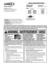
INSTALLATION
INSTRUCTIONS
VENTED GAS FIREPLACE HEATERS - DIRECT VENT MODELS
P/N 850,016M REV. H 08/2007
FOR YOUR SAFETY: Do not store or use gasoline
or other flammable vapors or liquids in the vicin-
ity of this or any other appliance.
FOR YOUR SAFETY: What to do if you smell gas:
• DO NOT light any appliance.
• DO NOT touch any electrical switches.
• DO NOT use any phone in your building.
• Immediately call your gas supplier from a
neighbor’s phone. Follow your gas suppliers
instructions.
• If your gas supplier cannot be reached, call the
fire department.
Installation and service must be performed by a
qualified installer, service agency or the gas
supplier.
MODELS
POUR VOTRE SÉCURITÉ: Ne pas entreposer ni utiliser
d'essence ni d'autre vapeurs ou liquides inflammables
dans le voisinage de cet appareil ou de tout autre
appareil.
POUR VOTRE SÉCURITÉ: Que faire si vous sentez une
odeur de gaz:
•Ne pas tenter d'allumer d'appareil.
•Ne touchez à aucun interrupteur. Ne pas vous servir
des téléphones se trouvant dans le batiment où
vous vous trouvez.
•Evacuez la piéce, le bâtiment ou la zone.
•Appelez immédiatement votre fournisseur de gaz
depuis un voisin. Suivez les instructions du
fournisseur.
•Si vous ne pouvez rejoindre le fournisseur de gaz,
appelez le service dos incendies.
L'installation et service doit être exécuté par un qualifié
installeur, agence de service ou le fournisseur de gaz.
DIRECT VENT
SPECTRA SERIES
This appliance may be installed in an aftermar-
ket permanently located, manufactured home
(USA only) or mobile home, where not prohib-
ited by local codes. This appliance is only for
use with the type of gas indicated on the rating
plate. This appliance is not convertible for use
with other gases, unless a certified kit is used.
LENNOX HEARTH PRODUCTS
OTL Report No. 116-F-02-05
LSS-35CN LSS-40CN
LSS-35CP LSS-40CP
WARNING: IF THE INFORMATION IN THIS MANUAL
IS NOT FOLLOWED EXACTLY, A FIRE OR EXPLO-
SION MAY RESULT CAUSING PROPERTY DAM-
AGE, PERSONAL INJURY OR LOSS OF LIFE.
AVERTISSEMENT: ASSUREZ-VOUS DE BIEN SUIVRE
LES INSTRUCTIONS DONNÉ DANS CETTE NOTICE POUR
RÉDUIRE AU MINIMUM LE RISQUE D'INCENDIE OU
POUR ÉVITER TOUT DOMMAGE MATÉRIEL, TOUTE
BLESSURE OU LA MORT.
A French manual is available upon request. Order Form Number
850,016CF.
Ce manuel d’installation est disponible en francais, simplement en
faire la demande. Numéro de la pièce 850,016CF.
INSTALLER: Leave this manual with the appliance.
CONSUMER: Retain this manual for future reference.

2NOTE: DIAGRAMS & ILLUSTRATIONS NOT TO SCALE.
TABLE OF CONTENTS
Packaging........................................ page 2
Introduction..................................... page 2
General Information......................... page 2
Location .......................................... page 3
Appliance and Vent Clearances....... page 4
Framing Specifications .................... page 5
Facing Requirements....................... page 6
Hearth Requirements....................... page 7
Fireplace Specifications ................... page 8
Vent Termination Clearances ........... page 9
Typical Installation Sequence .......... page 9
Detailed Installation Steps ............... page 9
Step 1. Framing ............................. page 9
Step 2. Routing Gas Line ............... page 11
Step 3. Install the Venting System. page 11
Vertical Termination Systems .......... page 11
Vent Section Length Chart............... page 12
Vertical Vent Tables and Figures...... page 15
Horizontal Termination System........ page 16
Horizontal Vent Tables and Figures . page 18
Venting Using Flexible Vent Pipe ..... page 20
Step 4. Field Wiring ....................... page 21
Step 5. Connecting Gas Line.......... page 21
Comfort Control Valve ..................... page 22
Step 6. Installing Ceramic Panels
And Logs ..................................... page 24
Step 7. Checking Unit Operation ..... page 24
Step 8. Installing Glass Door ......... page 24
Step 9. Burner Adjustments........... page 25
Finishing Requirements................... page 26
Cold Climate Insulation.................... page 26
Installation Accessories................... page 27
Gas Conversion Kits.................. page 28
DO NOT ATTEMPT TO ALTER OR MODIFY
THE CONSTRUCTION OF THE APPLIANCE OR
ITS COMPONENTS. ANY MODIFICATION OR
ALTERATION MAY VOID THE WARRANTY,
CERTIFICATION AND LISTINGS OF THIS UNIT.
INTRODUCTION
These fireplaces are designed, tested and listed
for operation and installation with, and only with,
Secure Vent™ Direct Vent System Components,
Secure Flex™ Flexible Vent Components manu-
factured by Security Chimneys International and
Z-Flex™ Model GA Venting Systems, listed to
UL1777 and ULCS635 manufactured by Flex-
master Canada Limited. These approved vent
system components are labeled for identifica-
tion. DO NOT use any other manufacturer's vent
components with these appliances.
These appliances comply with National Safety
Standards and are tested and listed by Omni-
Test Laboratories (Report No. 116-F-02-5) to
ANSI Z21.88 (in Canada, CSA-2.33), and CAN/
CGA-2.17-M91 in both USA and Canada, as
vented gas fireplace heaters.
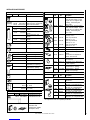
PACKAGING
The assembled Spectra direct vent gas fire-
place heater is packaged with:
1 -one log set located in firebox area.
2 -one envelope containing the literature
package which consists of the homeowner's
manual, installation instructions, log set
supplement and warranty; envelope is lo-
cated in the control area.
3 -one bag of glowing embers located in the
control area.
4 -one ceramic panel set, located on top of
unit.
5 -one hand held remote control, located in
the control area.
6 -an additional one of the following items
required:
1: Cast Iron Face (Classic Arch) and
Grillwork (Black, Gold or Nickel) or
2: Arched Face (Black, Gold or Nickel) or
3: Rectangular Face (Black, Gold or
Brushed Stainless)
Each kit comes with an individual set of
installation instructions.
Note: Installation and repair should be per-
formed by a qualified service person. The appli-
ance should be inspected annually by a quali-
fied professional service technician. More fre-
quent inspections and cleanings may be re-
quired due to excessive lint from carpeting,
bedding material, etc. It is imperative that the
control compartment, burners and circulating
air passage ways of the appliance be kept clean.
S'assurer que le brùleur et le compartiment
des commandes sont propres. Voir les in-
structions d'installation et d'utilisation qui
accompagnent l'appareil.
Provide adequate clearances around air open-
ings and adequate accessibility clearance for
service and proper operation. Never obstruct
the front openings of the appliance.
Please read and understand these
instructions before beginning your
installation.
GENERAL INFORMATION
Note: For combustible material refer to
Figure 48 on page 26.
These appliances are designed to operate on
natural or propane gas only.
This installation manual will help you obtain a
safe, efficient, dependable installation for your
appliance and vent system.
The Installation must conform to local codes
or, in the absence of local codes, with the
National Fuel Gas Code, ANSI Z223.1/NFPA
54
, or the
Natural Gas and Propane Installa-
tion Code, CSA B149.1
. The appliance, when
installed, must be electrically grounded in
accordance with local codes or, in the ab-
sence of local codes, with the
National Elec-
trical Code, ANSI/NFPA 70
, or the
Canadian
Electrical Code, CSA C22.1
.
These appliances are listed by Omni-Test
Laboratories for installation in bedrooms and
mobile homes.
WARNING: 1) FIRE HAZARD: DO NOT
PLACE ANY COMBUSTIBLE MATERIAL
OVER THE FIREPLACE OPENING. 2) DOOR
FRONT ACCESSIBILITY: ANY NON-COM-
BUSTIBLE FINISHING MATERIAL AREAS
THAT PROTRUDE MORE THAN 1" FROM
THE FACING SHOULD MAINTAIN A 9"
CLEARANCE TO THE FIREPLACE OPEN-
ING. SEE FIGURE 7, PAGE 6 FOR DETAILS.

3
NOTE: DIAGRAMS & ILLUSTRATIONS NOT TO SCALE.
Test gage connections are provided on the
front of the gas control valve (identified IN
for the inlet and OUT for the manifold side).
Do not use these appliances if any part has
been under water. Immediately call a quali-
fied, professional service technician to inspect
the appliance and to replace any parts of the
control system and any gas control which
have been under water.
Ne pas se servir de cet appareil s'il a été plongé
dans l'eau, complètement ou en partie. Appeler
un technicien qualifié pour inspecter l'appareil et
remplacer toute partie du système de contrôle et
toute commande qui ont été plongés dans l'eau.
These appliances feature a comfort control
valve which allows remote control of tem-
perature, fan and flame appearance. These
appliances also use a spark ignitor (piezo)
that allows the appliance's pilot gas to be lit
without the use of matches. This system
provides continued service in the event of a
power outage.
These appliances must not be connected to a
chimney or flue serving a separate solid fuel
burning appliance.
Carbon Monoxide Poisoning: Early signs of
carbon monoxide poisoning are similar to
the flu with headaches, dizziness and/or
nausea. If you have these signs, obtain
fresh air immediately. Turn off the gas sup-
ply to the appliance and have it serviced by
a qualified professional, as it may not be
operating correctly.
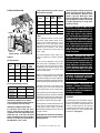
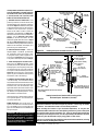
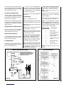
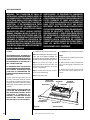
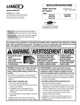
LOCATION
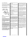
In selecting the location, the aesthetic and func-
tional use of the appliance are primary concerns.
However, vent system routing to the exterior and
access to the fuel supply are also important.
Consideration should be given to traffic ways,
furniture, draperies, etc., due to elevated surface
temperatures (
see Figure 2
).
Figure 1
TYPICAL INSTALLATION
Table 1
Installations at Altitudes of 0 to 4500 ft.-
Units are tested and approved for elevations
of 0 to 4500 feet (0 to 1372 meters).
Installations at Altitudes above 4500 ft.-
For elevations above 4500 feet (1372
meters), install the unit according to the
regulations of the local authorities having
jurisdiction and, in the USA, the latest
edition of the National Fuel Gas Code (ANSI
Z223.1) or, in Canada, the latest edition of
the CAN1-B149.1 and .2 codes.
Gas Inlet And Manifold Pressures
Gas Specifications
Table 1
shows the units' gas orifice size for
the elevations indicated.
ledoMleuF raeR renruB tnorF renruB
NC53-SSLsaG.taN44#05#
PC53-SSLsaGPL55#16#
NC04-SSLsaG.taN24#54#
PC04-SSLsaGPL"450.065#
These appliances must be isolated from the gas
supply piping system (by closing their individual
manual shut-off valve) during any pressure test-
ing of the gas supply piping system at test pres-
sures equal to or less than 1/2 psig (3.5 kPa).
These appliances and their individual shut-off
valves must be disconnected from the gas
supply piping system during any pressure
testing of that system at pressures in excess of
1/2 psig (3.5 kPa).
ledoMleuF mumixaM tupnI )H/UTB(
muminiM tupnI )H/UTB(
NC53-SSLsaG.taN000,33005,32
PC53-SSLsaGPL000,13005,32
NC04-SSLsaG.taN005,14004,82
PC04-SSLsaGPL000,93007,03
larutaN)enaporP(PL
muminiM erusserPtelnI .c.w"0.5.c.w"0.11
mumixaM erusserPtelnI .c.w"0.41.c.w"0.41
dlofinaM erusserP .c.w"5.3.c.w"0.01
The external electrical power (120V) is re-
quired to operate the provided circulating
blower.
Drywall
Mantel
Non-Combustible
Top Of
Fireplace Opening
WARNING: FAILURE TO COMPLY WITH
THE INSTALLATION AND OPERATING IN-
STRUCTIONS PROVIDED IN THIS DOCU-
MENT WILL RESULT IN AN IMPROP-
ERLY INSTALLED AND OPERATING AP-
PLIANCE, VOIDING ITS WARRANTY. ANY
CHANGE TO THIS APPLIANCE AND/OR
ITS OPERATING CONTROLS IS DANGER-
OUS. IMPROPER INSTALLATION OR USE
OF THIS APPLIANCE CAN CAUSE SERI-
OUS INJURY OR DEATH FROM FIRE,
BURNS, EXPLOSION OR CARBON MON-
OXIDE POISONING.
WARNING: CHILDREN AND ADULTS
SHOULD BE ALERTED TO THE HAZARDS
OF HIGH SURFACE TEMPERATURES. USE
CAUTION AROUND THE APPLIANCE TO
AVOID BURNS OR CLOTHING IGNITION.
YOUNG CHILDREN SHOULD BE CARE-
FULLY SUPERVISED WHEN THEY ARE IN
THE SAME ROOM AS THE APPLIANCE.
WARNING: DO NOT PLACE CLOTHING
OR OTHER FLAMMABLE MATERIALS
ON OR NEAR THIS APPLIANCE.
AVERTISSEMENT: SURVEILLER LES
ENFANTS. GARDER LES VÊTEMENTS,
LES MEUBLES, L'ESSENCE OU AUTRES
LIQUIDES À VAPEUR INFLAMMABLES
À COTE DE L'APPAREIL.

4NOTE: DIAGRAMS & ILLUSTRATIONS NOT TO SCALE.
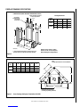
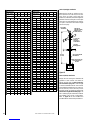
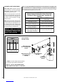
.oNledoM )mm(sehcnithgieHflehS
woblEeergeD09enOhtiw-tneVpoT
tneVeruceSxelFeruceS
53-SSL 2/175)1641(4/195)5051(
04-SSL )9941(95)3451(4/306
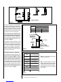
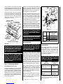
Shelf Height
(see table)
Do not insulate the
space between the
appliance and the
area above it.
Shelf Above Fireplace With Top Venting
12 ¹⁄₄”
(311mm)
*Note: For Secure Vent
A SV4.5L6 6” Section
(Cat. No. 77L70) Is Required.
*See Note
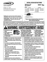
Figure 2
Figure 3
HORIZONTAL VENT VERTICAL VENT
TOP VENT
APPLICATIONS
*Note: 3 in. (75 mm) above any horizontal/
inclined vent component.
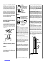
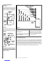
Note: The nailing flange and the cabinet
surfaces directly adjacent to the framing
member attached to the nailing flange, are
exempt from the 1/2" clearance to combus-
tibles defined for the rest of the cabinet
sides and back.
Table 2
KCAB )mm31(.ni2/1 srecaps)mm0(.ni0
SEDIS )mm31(.ni2/1 srecaps)mm0(.ni0
SRECAPSPOT)mm0(.ni0
ROOLF)mm0(.ni0
fomottoBmorF gnilieCottinU )mm6261(.ni46
TNEV*)mm4.52(.ni1
SECNARAELCECIVRES
TNORF)sretem9.0(.teeF3
Typical Locations
The location should also be free of electrical,
plumbing or other heating/air conditioning duct-
ing. These direct vent appliances are uniquely
suited for installations requiring a utility shelf
positioned directly above the fireplace. Utility
shelves like these are commonly used for locat-
ing television sets and decorative plants.
Do not insulate the space between the appli-
ance and the area above it. See
Figure 3
. The
minimum height from the base of the appliance
to the underside of combustible materials used
to construct a utility shelf in this fashion is shown
in the table in
Figure 3
.
The appliance should be mounted on a fully
supported base extending the full width and
depth of the unit. The appliance may be located
on or near conventional construction materi-
als. However, if installed on combustible ma-
terials, such as carpeting, vinyl tile, etc., a
metal or wood barrier covering the entire bot-
tom surface must be used.
APPLIANCE AND VENT CLEARANCES
These appliances are approved with zero clear-
ance from spacers to combustible materials on
all sides (as detailed in
Table 2
), with the
following exception: When the unit is installed
with one side flush with a perpendictular side
wall, the wall perpendicular to the opposite side
of the appliance front face must not extend
more than five inches beyond the front edge of
the unit. In addition, when the unit is recessed,
the side walls surrounding the unit must not
extend more than five inches beyond the front
edge of the unit. Refer to
Figure 2
.

5
NOTE: DIAGRAMS & ILLUSTRATIONS NOT TO SCALE.
Figure 4
Figure 5
Corner Framing with Square Termination (SV4.5HT)
Framing Dimensions
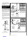
FIREPLACE FRAMING SPECIFICATIONS
A
B
7
(178)
(308)
(
267
)
C
VENT FRAMING -
TOP VENT WITH ONE
6” SECTION AND
ONE 90° ELBOW
Framing should be constructed
of 2x4 or larger lumber.
Inches (mm)
(130)
**FRAMING WITH SQUARE HORIZONTAL TERMINATIONS (SV4.5HT)
** See the horizontal venting Figures 29 and 30 on page 17 for
restrictions on the use of the square termination (SV4.5HT).
NOTE: For Secure Vent A 6” Section
SV4.5L6 (Cat. No. 77L70) Is Required
Before Installing The 90 Degree Elbow.
5-1/8
12-1/8
10-1/2
20-13/16
1/2 A
ledoM .oN ABCD E
53-SSL .ni538/161/5268/1938/16361/1151
mm2983851499819004
04-SSL .ni8/10461/5768/5748/58361/771
mm220101710121189344
C
Back wall of chase/enclosure
(including any finishing materials)
Note-
Venting requirements for corner installations -
D
A
B
E
ledoM .oN ABC
53-SSL .ni538/18/5248/115
mm29838019921
04-SSL .ni8/1048/1448/525
mm220112117331

6NOTE: DIAGRAMS & ILLUSTRATIONS NOT TO SCALE.
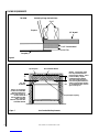
FACING REQUIREMENTS
Figure 6
Figure 7
Non-Combustible Requirements
Unit Nailing Flange (On Both Sides)
Fireplace
TOP VIEW
1/2” Drywall
Faceplate
3/8” Tile
1/2” Concrete Board
2” x 4”
9”
Min.
Requires A Concrete Board
(Or Other Non-Combustible
Material) Extending From
The Top Of The Fireplace To
The Floor And To The
Framing Members On Both
Sides. Do Not Use
Sheetrock, Plywood Or Other
Combustible Material
4 1/2” Min.
(Both Sides)
Top Of Fireplace Non-Combustible Material
Warning: 1) Fire Hazard: Do Not
Place Any Combustible Material
Over The Fireplace Opening. 2) Door
Front Accessibility: Any Non-
Combustible Finishing Material
Areas That Protrude More Than 1”
From The Facing Must Maintain A 9”
Clearance To The Fireplace Opening.
For Combustible Material, Refer To
Figure 48
On Page 26.
Top Of Fireplace Opening
10”

7
NOTE: DIAGRAMS & ILLUSTRATIONS NOT TO SCALE.
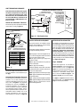
HEARTH REQUIREMENTS
Figure 8
Cement Board
Tile, Marble, Brick, Carpet,
Or Other Non-Combustible
Or Combustible Material
Fireplace
Stand
1”
Min.
Figure 9
RAISED FIREPLACE
Fireplace
Floor Plywood Platform
Face
Thickness Of the Floor Covering
(Carpet, Flooring, Etc.)
1” Min.

8NOTE: DIAGRAMS & ILLUSTRATIONS NOT TO SCALE.
Figure 10
FIREPLACE SPECIFICATIONS
H
ELECTRICAL
INLET
Diminsions In Inches (mm)
*
Includes The 1/2” Spacers
1 (25.4)
3 (76)
11 ¹⁄₄
(286) G
1/2” Spacers
8 ¹¹⁄₃₂
(211)
AE
D
F
B
C
1
(25.4)
3 (76)
GAS INLET
(BOTH SIDES)
*21 ³⁄₈
(543)
6
(152) 8 ¹³⁄₁₆
(225)
2 ⁹⁄₁₆
(65)
3
(76)
FRAMING SPACERS
CONCENTRIC FLUE
Combustion Air - 7 ¹⁄₂ (190)
Flue - 4 ¹⁄₂ (114)
3 (76)
Vent Restrictor
Adjustment Rod
ledoM .oN ABCDEFGH
53-SSL .ni8/38361/1532/1929161/3618/3132/1124/301
mm579198947384114797645372
04-SSL .ni8/79361/1042/1432/10261/3128/7232/1624/131
mm31018101678125835538376733

9
NOTE: DIAGRAMS & ILLUSTRATIONS NOT TO SCALE.
hctiPfooR)teef(H
21/6ottalF0.1
21/7ot21/6revO52.1
21/8ot21/7revO5.1
21/9ot21/8revO0.2
21/01ot21/9revO5.2
21/11ot21/01revO52.3
ot21/11revO 21/21 0.4
12 X
Roof Pitch is X/12
2 FT
MIN.
2 FT MIN. Lowest
Discharge
Opening
H*
*H = MINIMUM HEIGHT FROM ROOF TO
LOWEST DISCHARGE OPENING OF VENT
TERMINATION HEIGHTS FOR VENTS ABOVE
FLAT OR SLOPED ROOFS
Horizontal Overhang
Vertical
Wall
Vent
Termination
Storm Collar
Concentric
Vent Pipe
Flashing
1 inch (25.4 mm) Minimum
Clearance to Combustibles
Figure 11
Figure 12 -
Side Elevation View
3"
(76 mm)
12"
(305 mm)
Termination Kit
Combustible Projection
greater than inches in length
Combustible Projection
2-1/2 inches or less in length
18"
(457 mm)
Ventilated
Soffit Unventilated
Soffit
Horizontal Vent Termination Clearances
2-1/2
Termination Kit
All horizontal terminations
may be located as close
as 6” (152mm) to any
(non-combustible and
combustible) exterior
sidewall. This distance
may be decreased to
2” (51mm) for non-
combustible exterior
sidewalls only, if the
SV4.5HT-2 termination
is used.
Horizontal Vent Termination Clearances
The horizontal vent termination must have a
minimum of 3" (76 mm) clearance to any
overhead combustible projection of 2-1/2" (64
mm) or less. See
Figure 5.
For projections
exceeding 2-1/2" (64 mm), see
Figure 5
. All
horizontal terminations may be located as
close as 6" (152mm) to any (non-combustible
and combustible) exterior sidewall. This dis-
tance may be decreased to 2" (51mm) for non-
combustible exterior sidewalls only, if the
SV4.5HT-2 termination is used. For projec-
tions exceeding 2 ¹⁄₂" (64 mm), see
Figure 12
.
Terminate multiple vent terminations accord-
ing to the installation codes listed at the top of
this page.
Vertical Vent Termination Clearances
VENT TERMINATION CLEARANCES
These instructions should be used as a guide-
line and do not supersede local codes in any
way. Install vent according to local codes,
these instructions, the current National Fuel
Gas Code (ANSI-Z223.1) in the USA or the
current standards of CAN/CGA-B149.1 and -
B149.2 in Canada.
Terminate single vent caps relative to building
components according to
Figure 11
.
TYPICAL INSTALLATION SEQUENCE
The typical sequence of installation follows,
however, each installation is unique resulting in
variations to those described.
See the page numbers references in the follow-
ing steps for detailed procedures.
Step 1. (page 9) Construct the appliance fram-
ing. Position the appliance within the framing
and secure with nailing brackets.
Step 2. (page 11) Route gas supply line to
appliance location.
Step 3. (page 11) Install the vent system and
exterior termination.
Step 4. (page 21) Field Wiring
Install the operating control switch (not factory
provided) and bring in electrical service line for
forced air circulating blower.
Step 5. (page 21) Make connection to gas supply.
Step 6. (page 24) Install the ceramic panel, logs,
and glowing embers.
Step 7. (page 24) Checkout appliance operation.
Step 8. (page 25) Install glass door frame assembly.
Step 9. (page 25) Adjust burner to ensure
proper flame appearance.
DETAILED INSTALLATION STEPS
The appliance is shipped with all gas controls
and components installed and pre-wired. Re-
move the shipping carton, exposing the front
glass door. Remove ceramic panel kit from the
top of the fireplace and set it aside with care.
Remove the cardboard from underneath the
pressure relief plates. Open the two latches
(located under the firebox floor) securing the
glass door. Remove the door by tilting it out-
ward at the bottom and lifting it up. Set the door
aside protecting it from inadvertent damage.
See Figure 46 on page 25.
Step 1. FRAMING
Frame these appliances as illustrated in
Figure 4
on page 5, unless the appliance is
to be installed in a corner. See
Figure 5
on
page 5 for corner framing installations. All
framing details must allow for a minimum
clearance to combustible framing mem-
bers as shown in Table 2 on page 4. See
Figure 6
on page 6 for the facing detail.
See
Figure 7
on page 6 for the Non-Combus-
tible requirements. See
Figures 8 and 9
on
page 7 for Hearth Requirements.

10 NOTE: DIAGRAMS & ILLUSTRATIONS NOT TO SCALE.
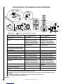
Figure 14
EXTERIOR HORIZONTAL VENT TERMINATION CLEARANCE REQUIREMENTS
V
VV
VV
F
C
Fixed
Closed
Window
Operable
Window
B
B
A
B
H
M
I
= Vent Terminal = Area where Terminal is not Permitted
= Air Supply Inlet
XV
D
V
3 ft.
3 ft.
AA
A
= 9” in U.S.
= 12” in Canada
V
L
B
J
XE
V
A
G
Inside
Corner Detail
*18”
Ventilated Soffit
Horizontal
Termination
Detail D
Exterior Wall Center Line
of Termination
18”
Inside Corner
B
C
C
C
*
See Item D in the Text Below.
*noitallatsnInaidanaC**noitallatsnISU
,hcrop,adnarev,edargevobaecnaraelC=A .ynoclabro,kced *)mc03(sehcni21**)mc03(sehcni21
ebyamtahtroodrowodniwotecnaraelC=B .denepo secnailpparof)mc51(ni6 )mc03(ni21,)Wk3(hutB000,01< dna)Wk3(hutB000,01>secnailpparof )mc19(sehcni63,)Wk03(hutB000,001< *)Wk03(hutB000,001>secnailpparof
secnailpparof)mc51(ni6 )mc32(ni9,)Wk3(hutB000,01< dna)Wk3(hutB000,01>secnailpparof )mc03(sehcni21,)Wk51(hutB000,05< **)Wk51(hutB000,05>secnailpparof
wodniwdesolcyltnenamrepotecnaraelC=C tneverpotdednemmocer)mm503("21 noitasnednocwodniw tneverpotdednemmocer)mm922("9 noitasnednocwodniw
tiffosdetalitnevotecnaraelclacitreV=D latnozirohanihtiwlanimretehtevobadetacol retnecehtmorf)mm854(sehcni81foecnatsid lanimretehtfoenil
)mm854("81)mm854("81
tiffosdetalitnevnuotecnaraelC=E)mm503("21)mm503("21
renrocedistuootecnaraelC=Fmuminim)mc7.21("5muminim)mc7.21("5
renrocedisniotecnaraelC=G •2-TH5.4VS-muminim)mc80.5("2 SSTH5.4VS-muminim)mc2.51("6 •2-TH5.4VS-muminim)mc80.5("2 SSTH5.4VS-muminim)mc2.51("6
enilretnecfoedisnihcaeotecnaraelC=H ylbmessarotaluger/retemevobadednetxe teef51fothgiehanihtiw)mc19(teef3 *ylbmessarotaluger/retemehtevoba teef51fothgiehanihtiw)mc19(teef3 **ylbmessarotaluger/retemehtevoba
teltuotnevrotalugerecivresotecnaraelC=I*)mc19(teef3**)mc19(teef3
telniylppusrialacinahcemnonotecnaraelC=J ynaottelnirianoitsubmocehtrognidliubot ecnailpparehto
secnailpparof)mc51(ni6 )mc03(ni21,)Wk3(hutB000,01< dna)Wk3(hutB000,01>secnailpparof )mc19(sehcni63,)Wk03(hutB000,001< *)Wk03(hutB000,001>secnailpparof
secnailpparof)mc51(ni6 )mc32(ni9,)Wk3(hutB000,01< dna)Wk3(hutB000,01>secnailpparof )mc03(sehcni21,)Wk51(hutB000,05< **)Wk51(hutB000,05>secnailpparof
telniylppusrialacinahcemaotecnaraelC=K*)m38.1(teef6 )m3(teef01nihtiwfievoba)mc19(teef3 **yllatnoziroh
devaproklawedisdevapevobaecnaraelC=L ytreporpcilbupnodetacolyawevid ‡)m31.2(teef7 ‡)m31.2(teef7
rokced,hcrop,adnarevrednuecnaraelC=M ynoclab ‡*)mc03(sehcni21 ‡)mc03(sehcni21
.edoCnoitallatsnIenaporPdnAsaGlanoitaN1.941B-ASCtnerrucehthtiwecnadroccanI* .sedoCsaGleuFlanoitaN45APFN/1.322ZSISNAtnerucehthtiwecnadroccanI** sevresdnasgnillewdylimafelgnisowtneewtebdetacolsihcihwyawevirddevaproklawedisaevobayltceridetanimrettonllahstnevA‡.sgnillewdhtob :roolfehthtaenebsedis2muminimanonepoyllufsiynoclabrokced,hcrop,adnarevfidettimrepylnO‡*.ylnO2-TH5.4VSrofselbitsubmoC-noNotecnaraelC"2•

11
NOTE: DIAGRAMS & ILLUSTRATIONS NOT TO SCALE.
Right Side
Front Corner of
Fireplace Framing
6"
(152 mm)
3"
(76 mm)
Figure 13
Step 3. INSTALL THE VENT SYSTEM
General Information
These instructions should be used as a guide-
line and do not supersede local codes in any
way. Install vent according to local codes,
these instructions, the current National Fuel
Gas Code (ANSI-Z223.1) in the USA or the
current standards of CAN/CGA-B149.1 and -
B149.2 in Canada.
These fireplaces are designed, tested
and listed for operation and installation
with, and only with, Secure Vent™ Direct
Vent System Components, Secure Flex™
Flexible Vent Components manufactured
by Security Chimneys International and
Z-FLEX™ Model GA Venting Systems listed
to UL1777 and ULCS635 manufactured by
Flexmaster Canada Limited.
These approved vent system components
are labeled for identification.
DO NOT
use any other manufacturer's vent
components with these appliances.
Some local jurisdictions may require the gap
between the outer wall of the vent system
and the firestop penetration opening to be
sealed. This is not a requirement of the
listing of this product, however this gap may
be sealed using aluminized tape or similar
non-combustible material.
The vent system may not service multiple appli-
ances, and must never be connected to a flue
serving a solid fuel burning appliance. The vent
pipe is tested to be run inside an enclosing wall
(such as a chase). There is no requirement for
inspection openings in the enclosing wall at any
of the joints in the vent pipe.
Select Venting System - Horizontal or Vertical
With the appliance secured in framing, deter-
mine vent routing and identify the exterior
termination location. The following sections
describe vertical (roof) and horizontal (exte-
rior wall) vent applications. Refer to the sec-
tion relating to your installation. A list of
approved venting components is shown in
the two tables on page 27.
VERTICAL TERMINATION SYSTEMS (ROOF)
Figure 15, and Figures 25 through 27 on
pages 12 and 15
and their associated
Vertical Vent Tables illustrate the various verti-
cal venting configurations that are possible for
use with these appliances. Secure Vent pipe
applications are shown in these figures; Secure
Flex pipe may also be used. A Vertical Vent
Table summarizes each system’s minimum
and maximum vertical and horizontal length
values that can be used to design and install the
vent components in a variety of applications.
Both these vertical vent systems terminate
through the roof. The minimum vent height
above the roof and/or adjacent walls is speci-
fied in ANSI Z223.1-(latest edition) (In Canada,
the current CAN-1 B149 installation code) by
major building codes. Always consult your
local codes for specific requirements. A gen-
eral guide to follow is the Gas Vent Rule (refer
to
Figure 11
on page 9).
Massachusetts And New York City, NY
Requirements
These appliances are approved for installation
in the following USA locations listed in the
following:
Massachusetts:
Installation of these fireplaces are approved
for installation in the US state of Massachu-
setts if the following additional requirements
are met-
• Installation and repair must be done by a
plumber or gas fitter licensed in the Common-
wealth of Massachusetts.
• The flexible gas line connector used shall not
exceed 36 inches (92 centimeters) in length.
• The individual manual shut-off must be a T-
handle type valve.
New York City, NY:
Installation of these fireplaces are approved
for installation in New Your City in the US state
of New York.
Massachusetts Horizontal Vent Requirements
In the Commonwealth of Massachusetts, hori-
zontal terminations installed less than seven
(7) feet above the finished grade must comply
with the following additional requirements:
• A hard wired carbon monoxide detector with
an alarm and battery back-up must be installed
on the floor level where the gas fireplace is
installed. The carbon monoxide detector must
comply with NFPA 720, be ANSI/UL 2034
listed and be ISA certified.
• A metal or plastic identification plate must be
permanently mounted to the exterior of the
building at a minimum height of eight (8) feet
above grade and be directly in line with the
horizontal termination. The sign must read, in
print size no less than one-half (1/2) inch in
size, GAS VENT DIRECTLY BELOW. KEEP
CLEAR OF ALL OBSTRUCTIONS.
These fireplaces must be vented directly
to the outside.
Step 2. ROUTING GAS LINE
Route a 1/2" (13 mm) gas line along the inside
of the right side framing as shown in
Figure 13
.
Gas lines must be routed, constructed and
made of materials that are in strict accordance
with local codes and regulations.
All appliances are factory-equipped with a flex-
ible gas line connector and 1/2" inch shutoff
valve. (See step 5 on page 21).

12 NOTE: DIAGRAMS & ILLUSTRATIONS NOT TO SCALE.
Figure 15
Vertical (Offset) Installation
Analyze the vent routing and determine the
quantities of vent sections and number of
elbows required. Refer to Vertical Vent Fig-
ures and Tables on page 15 to select the type
of vertical installation desired. Vent sections
are available in net lengths of 4-1/2" (114 mm),
10-1/2" (267 mm), 22-1/2" (572 mm), 34-1/2"
(876 mm) and 46-1/2" (1181 mm). Refer to the
Vent Section Length Chart on this page for an
aid in selecting length combinations. Elbows
are available in 90° and 45° configurations.
Refer to
Figure 20
for the SV4.5E45 and
SV4.5E90 elbow dimensional specifications.
TRAHCHTGNELNOITCESTNEV
noitceSlanimoN )sehcni(htgneL 621426384T
O
T
A
L
Q
T
Y
noitceSteN )sehcni(htgneL 2/1-42/1-012/1-222/1-432/1-64
tneVfothgieHsnoitceStneVforebmuN
sehcnitf
44121100034
0515.21010034
5.451578.21110035
5.061573.31020035
5.271573.41000505
77157.41100506
38152.51010506
6815.51000044
5.091578.51100045
5.691573.61010045
5.502521.71011507
70252.71000606
5.112526.71100607
5.712521.81010607
5.922521.91001607
5.232573.91000055
73257.91100056
5.142521.02000707
6425.02100708
25212010708
46222001708
67232000808
97252.32000066
5.082573.32100809
5.382526.32100067
5.982521.42010067
5.103521.52001067
5.013578.52000909
5135.621009001
5.523521.72000077
0335.72100078
63382010078
54357.8200001001
5.943521.9210001011
27313000088
5.673573.13100089
5.973526.1300011011
5.814578.43000099
32452.531000901
56457.8300000101
TRAHCHTGNELNOITCESTNEV
noitceSlanimoN )sehcni(htgneL 621426384T
O
T
A
L
Q
T
Y
noitceSteN )sehcni(htgneL 2/1-42/1-012/1-222/1-432/1-64
tneVfothgieHsnoitceStneVforebmuN
sehcnitf
5.4573.0100001
957.0200002
5.01578.0010001
5152.1110002
5.91526.12100
03
1257.1020002
5.22578.1001001
5.52521.2120003
5.13526.2030003
5.43578.2000101
5.73521.3111003
5.34526.3021003
5457.3002002
5.64578.3000011
5.94521.4102003
1552.4100012
5.55526.4012003
7557.4001102
6652.5022004
5.76526.5003003
9657.5000202
27 6 103004
5.37521.6100203
5.97526.6010203
1857.6000112
095.7021014
5.19526.7002013
3957.7000022
69 8 101204
5.79521.8100023
2015.8200024
5.301526.8000303
801 9 100304
4115.9020024
71157.9105006
5.811578.9110305
6215.01001304
5.031578.01101305
53152.11006006
8315.11000404
5.931526.11000033
5.241578.11100405
Vertical (Straight) Installation
Determine the number of straight vent sec-
tions required. 4-1/2" (114 mm), 10-1/2" (267
mm), 22-1/2" (572 mm), 34-1/2" (876 mm)
and 46-1/2" (1181 mm) net section lengths are
available. Plan the vent lengths so that a joint
does not occur at the intersection of ceiling or
roof joists. Refer to the Vent Section Length
Chart on this page.
SV4.5CGV-1
Termination SV4.5FA OR
SV4.5FB Flashing
AND SV4.5SC
STORM COLLAR
*SV4.5VF
Firestop/Spacer
SV4.5L6/12/24/36/48
Vent Sections
40' Max
(12.2 M)
1" (25.4 mm)
Minimum
Clearance to
Combustibles
*When using Secure Flex,
use Firestop/Spacer
SF4.5VF

13
NOTE: DIAGRAMS & ILLUSTRATIONS NOT TO SCALE.
Figure 19
Support Straps
(Plumber’s tape)
8 feet (2.4 m)
Maximum
Blocking
Figure 18
Figure 17
Figure 16
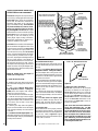
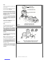
B. Attach vent components to appliance -
Secure Vent SV4.5 direct vent system compo-
nents are unitized concentric pipe components
featuring positive twist lock connections (
see
Figure 17
).
All of the appliances covered in this document are
fitted with collars having locking inclined chan-
nels. The dimpled end of the vent components fit
over the appliance collar to create the positive
twist lock connection.
First Vent
Component
Align the dimple (four places)
with the opening of the locking
incline channel on appliance
collar. Twist vent component
clockwise to engage and seal.
Locking
Incline Channel
Dimple
Appliance collar
Vent / Appliance Collar
Connection
Align the dimple (four places) of the
upper vent section with the opening of
the locking incline channel on the
lower vent section. Twist vent
component clockwise to engage and
seal until arrow and dimple align.
Locking
Incline Channel
Dimple
Arrow
Connected
Vent Sections
Vent / Vent Section
Connection
Arrow
Arrow
To attach a vent component to the appliance
collar, align the dimpled end over the collar,
adjusting the radial alignment until the four
locking dimples are aligned with the inlet of the
four inclined channels on the collar (
refer to
Figure 17
). Push the vent component against
the collar until it fully engages, then twist the
component clockwise, running the dimples
down and along the incline channels until they
seat at the end of the channels.
The unitized design of the Secure Vent com-
ponents will engage and seal both the inner
and outer pipe without the need for sealant or
screws. If desired, a #6 x 1/2" screw may be
used at the joint, but is not required as the pipe
will securely lock when twisted.
C. Attach vent components to each other -
Other vent sections may be added to the previ-
ously installed section in accordance with the
requirements of the vertical vent figures and
tables. To add another vent component to a
length of vent run, align the dimpled end over the
inclined channel end of the previously installed
section, adjusting the radial alignment until the
four locking dimples are aligned with the inlets of
the four incline channels of the previous section.
10¹⁄₂” Min.
(267 mm)
10¹⁄₂” Min.
(267 mm)
Push the vent component against the previous
section until it fully engages, then twist the
component clockwise running the dimples down
and along the incline channels until they seat at
the end of the channels. This seating position
is indicated by the alignment of the arrow and
dimple as shown in
Figure 18.
D. Install firestop/spacer at ceiling - When using
Secure Vent, use SV4.5VF firestop/spacer at ceil-
ing joists; when using Secure Flex, use SF4.5VF
firestop/spacer. If there is living space above the
ceiling level, the firestop/spacer must be installed
on the bottom side of the ceiling. If attic space is
above the ceiling, the firestop/spacer must be
installed on the top side of the joist. Route the vent
sections through the framed opening and secure
the firestop/spacer with 8d nails or other appro-
priate fasteners at each corner.
Remember to maintain 1" (25 mm) clearance
to combustibles, framing members, and attic
or ceiling insulation when running vertical
chimney sections.
E. Support the vertical vent run sections -
Support the vertical portion of the venting sys-
tem every 8 feet (2.4m) above the fireplace vent
outlet using field provided support straps (con-
ventional plumber's tape).
Secure the plumber's
tape to the framing members with nails or screws.
Loop the tape around the vent, securing the
ends of the tape to the framing. If desired,
sheet metal screws #6 x 1/2" length may be
used to secure the support straps to the vent
pipe . See
Figure 19.
Where required, a telescopic vent section
(SV4.5LA) may be used to provide the in-
staller with an option in installing in tight and
confined spaces or where the vent run made
up of fixed length pieces develops a joint in a
undesirable location, or will not build up to the
required length. The SV4.5LA Telescopic Vent
Section has an effective length of from 1-1/2"
(38 mm) to 7-1/2" (191 mm). The SV4.5LA is
fitted with a locking inclined channel end (iden-
tical to a normal vent section component) and
a plain end with 3 pilot holes. Slip the plain end
over the locking channel end of a standard
SV4.5 vent component the required distance
and secure with three screws.
Maintain a minimum 1" (25 mm) clearance to
combustible materials for all vertical elements.
Clearances for all horizontal elements are 3"
(76 mm) on top, 1" (25 mm) on sides and 1"
(25 mm) on the bottom.
A. Frame ceiling opening - Use a plumb line
from the ceiling above the appliance to locate
center of the vertical run. Cut and/or frame an
opening, 10-1/2" x 10-1/2" (267mm x 267mm)
inside dimensions, about this center mark
(
Figure 16
).

14 NOTE: DIAGRAMS & ILLUSTRATIONS NOT TO SCALE.
Figure 21
Figure 22
Figure 24
Figure 23
K. Install the vertical termination - The final
step involves installation of the SV4.5CGV-1
Vertical Termination. Extend the vent sections to
the height as shown in the "Vertical vent termina-
tion section" on page 9. The SV4.5CGV-1 Ver-
tical Termination (
Figure 24
) installs in the exact
same fashion as any other Secure Vent section.
Align the termination over the end of the previ-
ously installed section, adjusting the radial align-
ment until the locking dimples of the termination
are aligned with the inlets of the four incline
channels of the last vent section. Push the
termination down until it fully engages, then
twist the termination clockwise running the
dimples down and along the incline channels
until they seat at the end of the channels.
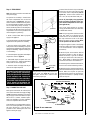
I. Install the roof flashing - Extend the vent
sections through the roof structure. Install the
roof flashing over the vent section and position
such that the vent column rises vertically (use
carpenters level) (
Figure 22
). Nail along perim-
eter to secure flashing or adjust roofing to over-
lap the flashing edges at top and sides only and
trim where necessary. Seal the top and both
sides of the flashing with waterproof caulking.
If the vent system extends more than 5' (1.5 m)
above the roof flashing, stabilizers may be nec-
essary. Additional screws may be used at section
joints for added stability. Guide wires may be
attached to the joint for additional support on
multiple joint configurations.
G. Continue installation of horizontal/inclined
sections - Continue with the installation of the
straight vent sections in horizontal/inclined run
as described in Step C. Install support straps
every 5' (1.52 m) along horizontal/inclined vent
runs using conventional plumber’s tape. It is
very important that the horizontal/inclined
run be maintained in a straight (no dips) and
recommended to be in a slightly elevated
plane, in a direction away from the fireplace
of 1/4" rise per foot (20 mm per meter) which is
ideal, though rise per foot run ratios that are
smaller are acceptable all the way down to at or
near level. Use a carpenter’s level to measure
from a constant surface and adjust the support
straps as necessary.
It is important to maintain the required clear-
ances to combustibles: 1" (25 mm) at all sides
for all vertical runs; and 3" (76 mm) at the top,
1" (25 mm) at sides, and 1" (25 mm) at the
bottom for all horizontal/inclined runs.
H. Frame roof opening - Identify location for
vent at the roof. Cut and/or frame opening per
Roof Framing Chart and
Figure 21
.
J. Install the storm collar - Install the storm
collar, supplied with the flashing, over the
vent/flashing joint. See
Figure 23.
Loosen the
storm collar screw. Slide collar down until it
meets the top of the flashing. Tighten the
adjusting screw. Apply non-combustible caulk-
ing or mastic around the circumference of the
joint to provide a water tight seal.
C
D
Storm
Collar
Figure 20
F. Change vent direction to horizontal/in-
clined run - At transition from or to a horizon-
tal/inclined run, install the SV4.5E45 and
SV4.5E90 elbows in the same manner as the
straight vent sections. The elbows feature a
twist section to allow them to be routed about
the center axis of their initial collar section to
align with the required direction of the next
vent run element. Twist elbow sections in a
clockwise direction only so as to avoid the
possiblity of unlocking any of the previously
connected vent sections. See
Figure 20
.
SV4.5E90
(90° Elbow)
7 ⁵⁄₈"
(194 mm)
Swivel Joint
(360° swivel)
4 ¹³⁄₁₆"
(122 mm)
SV4.5E45
(45° Elbow)
Swivel Joint
(360° swivel)
Framing Dimensions for Roof
Pitch C D
0/12 10-1/2 in. 10-1/2 in.
(267 mm) (267 mm)
6/12 10-1/2 in. 12 in.
(267 mm) (305 mm)
12/12 10-1/2 in. 17-3/4 in.
(267 mm) (451 mm)

15
NOTE: DIAGRAMS & ILLUSTRATIONS NOT TO SCALE.
Figure 25
- Top Vent - STRAIGHT
Figure 26
-
Top Vent - TWO 90 DEGREE ELBOWS
VERTICAL VENT FIGURES/TABLES
Note: Secure Vent (rigid vent pipe) is shown
in the figures; Secure Flex (flexible vent pipe)
may also be used.
Note: It is very important that the horizontal/
inclined run be maintained in a straight (no
dips) and recommended to be in a slightly
elevated plane, in a direction away from the
fireplace of 1/4" rise per foot (20 mm per
meter) which is ideal, though rise per foot run
ratios that are smaller are acceptable all the
way down to at or near level.
Note: SV4.5VF (Secure Vent), SF4.5VF (Se-
cure Flex) firestop/spacer must be used any-
time vent pipe passes through a combustible
floor or ceiling. SV4.5HF (Secure Vent),
SF4.5HF (Secure Flex)firestop/spacer must be
used anytime vent pipe passes through a com-
bustible wall.
Note: Two 45 degree elbows may be used in
place of one 90 degree elbow. The same rise to
run ratios, as shown in the venting figures for
90 elbows, must be followed if 45 degree
elbows are used.
AELBAT
VM
MUMINI
HmumixaM
teef)sretem(teef)sretem(
1*)503.0(5)25.1(
2)016.0(01)1.3(
3)419.0(51)56.4(
4)22.1(02)2.6(
V+V
1
.xaM)m4.21(teef04=H+
H.xaM)m2.6(teef02=
Figure 27 -
Top Vent - THREE ELBOWS
BELBAT
VM
MUMINI
HH+
1
mumixaM
teef)m(teef)m(
1)503.0(5)25.1(
2)016.0(01)1.3(
3)419.0(51)56.4(
4)22.1(02)2.6(
H+H
1
.xaM)m2.6(teef02=V+V
1
H+H+
1
teef04= .xaM)m4.21(
40 feet (12.2 meters)
Maximum
*Ceiling
Firestop/Spacer
(SV4.5VF)
*When using
Secure Flex, use
Firestop/Spacer
SF4.5VF
V
H1
H
V1
*Ceiling
Firestop/Spacer
(SV4.5VF) **Wall
Firestop/Spacer
(SV4.5HF)
*When using Secure Flex,
use Firestop/Spacer
SF4.5VF
**When using Secure
Flex, use Firestop/Spacer
SF4.5HF
WARNING: UNDER NO CIRCUM-
STANCES MAY SEPARATE SECTIONS
OF CONCENTRIC FLEXIBLE VENT PIPE
BE JOINED TOGETHER.
*When developing chimney systems
with horizontal runs (H) that end with
a vertical run (V1), it is allowable to
use an elbow attached directly to the
top collar. Count the elbow attached
to the collar as 1 foot of (V) run.
H
V
V1
*Ceiling
Firestop/Spacer
(SV4.5VF)
**Wall
Firestop/Spacer
(SV4.5HF)
**When using Secure
Flex, use Firestop/Spacer
SF4.5HF
*When using Secure Flex,
use Firestop/Spacer
SF4.5VF

16 NOTE: DIAGRAMS & ILLUSTRATIONS NOT TO SCALE.
Vertical
Rise
SV4.5E90
Elbow
Horizontal / Inclined Run SV4.5 HT
Termination
Firestop/Spacer
SV4.5L6/12/24/36/48
Vent Sections
Support Bracket Spacing
Every 5 ft (1.52 m)
See Figure 19 on page 13 for
vertical vent section support.
SV4.5 HT
Termination
Support
Brackets
Building
Support
Framing
Ceiling
Fireplace
Exterior
Wall
Exterior
Wall
TYPICAL HORIZONTAL VENT INSTALLATION
Figure 28
Secure Vent SV4.5 direct vent system compo-
nents are unitized concentric pipe components
featuring positive twist lock connection, (
refer to
Figure 17
on page 13). All of the appliances
covered in this document are fitted with collars
having locking inclined channels. The dimpled
end of the vent components fit over the appliance
collar to create the positive twist lock connection.
A. Plan the vent run -
Analyze the vent routing and determine the
types and quantities of sections required
4-1/2" (114 mm), 10-1/2" (267 mm), 22-1/2"
(572 mm), 34-1/2" (876 mm) and 46-1/2" (1181
mm) net section lengths are available. Plan the
vent lengths so that a joint does not occur at the
intersection of ceiling or roof joists. Make al-
lowances for elbows as indicated in
Figure 20
on page 13
. Maintain a minimum 1" (25 mm)
clearance to combustibles on the vertical sec-
tions. Clearances for the horizontal runs are; 3" (76
mm) on top, 1" (25 mm) on sides, and 1" (25 mm)
at the bottom.
B. Frame exterior wall opening -
Locate the center of the vent outlet on the
exterior wall according to the dimensions shown
in
Figure 4
on page 5. Cut and/or frame an
opening, 10-1/2" x 12-1/8" (267 mm x 267
mm) inside dimensions, about this center.
C. Frame ceiling opening - If the vertical
route is to penetrate a ceiling, use plumb line
to locate the center above the appliance. Cut
and/or frame an opening, 10-1/2" x 10-1/2"
(267 mm x 267 mm) inside dimensions, about
this center (refer to
Figure 16
on page 12 ).
D. Attach vent components to appliance - To
attach a vent component to the appliance collar,
align the dimpled end over the collar, adjusting the
radial alignment until the four locking dimples are
aligned with the inlets of the four incline channels
on the collar (
refer to Figure 17
on page 13).
G. Support the vertical run sections -
See Section E on page 13.
Push the vent component against the collar until it
fully engages, then twist the component clockwise,
running the dimples down and along the incline
channels until they seat at the end of the channels.
The unitized design of the Secure Vent compo-
nents will engage and seal both the inner and outer
pipe elements with the same procedure. Sealant
and securing screws are not required.
E. Attach vent components to each other -
Other vent sections may be added to the previ-
ously installed section in accordance with the
requirements of the vent tables. To add another
vent component to a length of vent run, align the
dimpled end of the component over the inclined
channel end of the previously installed section,
adjusting the radial alignment until the four lock-
ing dimples are aligned with the inlets of the four
incline channels of the previous section. Push
the vent component against the previous section
until it fully engages, then twist the component
clockwise running the dimples down and along
the incline channels until they seat at the end of
the channels.This seating position is indicated
by the alignment of the arrow and dimple as
shown in
Figure 18 on page 13.
F. Install firestop/spacer at ceiling -
When using Secure Vent, use SV4.5VF firestop/
spacer at ceiling joists; when using Secure Flex, use
SF4.5VF firestop/spacer. If there is living space
above the ceiling level, the firestop/ spacer must be
installed on the bottom side of the ceiling. If attic
space is above the ceiling, the firestop/ spacer must
be installed on the top side of the joist. Route the
vent sections through the framed opening and
secure the firestop/spacer with 8d nails or other
appropriate fasteners at each corner.
I. Continue installation of horizontal/inclined
sections - Continue with the installation of the
straight vent sections in horizontal/inclined run
as described in Step E. Install support straps
every 5 ft. (1.52 m) along horizontal/inclined
vent runs using conventional plumber’s tape.
See
Figure 28.
It is very important that the
horizontal/inclined run be maintained in a
straight (no dips) and recommended to be in
a slightly elevated plane, in a direction away
from the fireplace of 1/4" rise per foot (20 mm
per meter) which is ideal, though rise per foot
run ratios that are smaller are acceptable all the
way down to at or near level. Use a carpenter’s
level to measure from a constant surface and
adjust the support straps as necessary.
Both of these horizontal vent systems terminate
through an outside wall. Building Codes limit or
prohibit terminating in specific areas. Refer to
Figure 14
on page 10 for location guidelines.
Figure 28, and Figures 31 to 33 on pages 16,
18 and 19
and their associated Horizontal Vent
Table illustrate the various horizontal venting
configurations that are possible for use with
these appliances. Secure Vent pipe applica-
tions are shown in these figures; Secure Flex
pipe may also be used. A Horizontal Vent Table
summarizes each system’s minimum and maxi-
mum vertical and horizontal length values that
can be used to design and install the vent
components in a variety of applications.
HORIZONTAL (OUTSIDE WALL)
TERMINATION SYSTEM
H. Change vent direction - At transition from
or to a horizontal/inclined run, install the
SV4.5E45 and SV4.5E90 elbows in the same
manner as the straight vent sections. The
elbows feature a twist section to allow them
to be routed about the center axis of their
initial collar section to align with the re-
quired direction of the next vent run element.
Twist elbow sections in a clockwise direc-
tion only so as to avoid the possiblity of
unlocking any of the previously connected
vent sections. See
Figure 20
.
Remember to maintain 1" (25 mm) clear-
ance to combustibles, framing members,
and attic or ceiling insulation when running
vertical chimney sections.

17
NOTE: DIAGRAMS & ILLUSTRATIONS NOT TO SCALE.
Firestop/Spacer (SV4.5HF) shown
on the exterior side of the wall. It
may also be installed on the
interior side. SV4.5 HT
Termination
10¹⁄₂"
(267mm)
7"
(178)
5¹⁄₈"
(130 mm)
12¹⁄₈"
(308 mm)
Note: Centerline of Vent Piping is
NOT the Same as the Centerline of
the Framed Opening.
6 to 48 inch Vent Section,
Telescopic vent section,
Elbow or Appliance Collar
See Figure 4 on page 5
for Min. Distance to Base
of Appliance.
Base of Appliance
3"
(76 mm)
1"
(25.4 mm)
Adapter
SV4.5RCH
IMPORTANT: The vent termination is hot
while in operation and for a period of time
following use of the fireplace. To prevent
contact with hot surfaces, we recommend
the use of a Termination Guard. This can be
purchased at your local dealer.
Horizontal terminations have been designed to perform in a wide range of weather
conditions. Our terminations meet or exceed industry standards.
When selecting the locations of your horizontal terminations, do not place the
termination where water from eaves and adjoining rooflines may create a heavy flow
of cascading water onto the termination cap. If the cap must be placed where the
possibility of cascading water exists, it is the responsibility of the builder to direct the
water away from the termination cap by using gutters or other means.
Take care to carefully follow the installation instructions for the termination, including
the use of silicone caulking where required.
Figure 29
Figure 30
Siding
Stucco 1¹⁄₄" Maximum Recess of
Either Square Termination into
Exterior Finishing Material
Exterior Surface of
Framing
5 in. to 9 ¹₄ in.
(127 to 235 mm)
Exterior Surface of Siding
Minimum wall thickness
5 in. (127 mm)
Interior Surface of
Finished Wall
Maximum wall thickness
9¹₄ in.(235 mm)
SV4.5HT
Square
Termination
Maximum Extent of
Vent Run Sections
Relative to Exterior
Surface of Framing
Last Vent Section. Use
Telescopic Vent
Section (SV4.5LA), If
Necessary
Adapter
SV4.5RCH
(Provided With The
Termination)
SV4.5HT
Square Termination
Venting Connection and Exterior Wall Recessing of the
Horizontal Square Termination (SV4.5HT).
Note: Venting terminals shall not be recessed into
a wall or siding.
It is important to maintain the required clear-
ances to combustibles: 1" (25 mm) at all sides
for all vertical runs; and 3" (76 mm) at the top,
1" (25 mm) at sides, and 1" (25 mm) at the
bottom for all horizontal/inclined runs
J. Assemble vent run to exterior wall - If not
previously measured, locate the center of the
vent at the exterior wall. Prepare an opening as
described in Step B. Assemble the vent system
to point where the terminus of the last section
is within 5 in. (127 mm) to 9-1/4 in. (235 mm)
inboard of the exterior surface to which the
termination is to be attached, see
Figure 30
. If
the terminus of the last section is not within this
distance, use the telescopic vent section
SV4.5LA, as the last vent section. For wall
thicknesses greater than that shown in
Figure
30
, refer to
Table 3 on page 18
. This table lists
the additional venting components needed (in
addition to the termination and adapter) for a
particular range of wall thicknesses.
K. Attach termination adapter - Attach the
adapter (adapter - SV4.5RCH - provided with
the termination) to the vent section or tele-
scoping vent section), elbow or appliance col-
lar as shown in
Figure 29
in the same manner
as any SV4.5 vent component (refer to Step E).
L. Install Firestop/Spacer at exterior wall -
When using the square termination, install
SV4.5HF (Secure Vent), SF4.5HF (Secure Flex)
Firestop/Spacer over the opening at the exte-
rior side of the framing, long side up, with the
3 inch spacer clearance at the top as shown in
Figure 29
, and nail into place. (The Firestop/
Spacer may also be installed over the opening
at the interior side of the framing).
1. Install the square termination (SV4.5HT-2)
- For the last step , from outside the exterior
wall, slide the collars of the termination onto the
adapter (the outer over the outer and the inner
inside the inner) until the termination seats
against the exterior wall surface to which it will
be attached. Orient the housing of the termina-
tion with the arrow pointed upwards. Secure
the termination to the exterior wall.
Orient the housing of the termination with the
arrow pointed upwards. Secure the termina-
tion to the exterior wall.
SFHRK Snorkel Cap –The snorkel cap is de-
signed to be fitted into a basement window
box. The SFHRK cap is for use with flex vent
pipe. The SV4.5HRK14 and SV4.5HRK36 are
for rigid vent pipe.
Installing the Square Horizontal Termination (SV4.5HT-2).

18 NOTE: DIAGRAMS & ILLUSTRATIONS NOT TO SCALE.
H
V
**Wall Firestop/Spacer
(SV4.5HF)
**When using Secure
Flex, use Firestop/Spacer
SF4.5VF
*Ceiling
Firestop/Spacer
(SV4.5VF)
*When using Secure Flex,
use Firestop/Spacer
SF4.5HF
3ELBAT llaWroiretxEsuoiraVrofderiuqeRstnenopmoCgnitneV tiKnoitanimreTerauqSehTgnisUnehW,sessenkcihT )TH5.4VS(
deriuqeRstnenopmoCgnitneV sessenkcihTllaWroiretxE mm(sehcni )
ylnOtiKnoitanimreT4/19ot5)532ot721(
tnev.ni6dnatiKnoitanimreT )6L5.4VS(noitces )943ot532(4/331ot4/19
tnev.ni21dnatiKnoitanimreT )21L5.4VS(noitces )205ot004(4/391ot4/351
cipocseleTdnatiKnoitanimreT .ni6dna)AL5.4VS(noitces )6L5.4VS(noitcestnev )725ot372(4/302ot4/301
Figure 31
-
Top Vent - ONE 90 DEGREE ELBOW -
ELBOW CONNECTION NOT DIRECTLY AT APPLIANCE
See
Table 3
as an aid in venting component selection
for a particular range of exterior wall thicknesses.
HORIZONTAL VENT FIGURES/TABLES
Note: Secure Vent components (rigid vent
pipe and terminal) are shown in the figures;
Secure Flex components (flexible vent pipe
and terminal) may also be used.
Note: Two 45 degree elbows may be used in
place of one 90 degree elbow. The same rise to
run ratios, as shown in the venting figures for
90 elbows, must be followed if 45 degree
elbows are used.
Note: It is very important that the horizontal/inclined run be maintained in a straight (no dips)
and recommended to be in a slightly elevated plane, in a direction away from the fireplace of
1/4" rise per foot (20 mm per meter) which is ideal, though rise per foot run ratios that are smaller
are acceptable all the way down to at or near level.
Square termination
(SV4.5HT-2) shown.
Note: SV4.5VF (Secure Vent), SF4.5VF (Secure
Flex) firestop/spacer must be used anytime vent
pipe passes through a combustible floor or ceil-
ing. SV4.5HF (Secure Vent), SF4.5HF (Secure
Flex) firestop/spacer must be used anytime vent
pipe passes through a combustible wall.
ELBATC
muminiMVmumixaMH
teef)m(teef)m(
1)503.0(4/13)86.1(
2)16.0(01)1.3(
3)419.0(51)56.4(
4)22.1(02)2.6( .xaM)m4.21(teef04=H+V .xaM)m2.6(teef02=H
WARNING: UNDER NO CIRCUM-
STANCES MAY SEPARATE SECTIONS
OF CONCENTRIC FLEXIBLE VENT
PIPE BE JOINED TOGETHER.

19
NOTE: DIAGRAMS & ILLUSTRATIONS NOT TO SCALE.
V
H
H1
*Wall Firestop/Spacer
(SV4.5HF)
*Wall Firestop/Spacer
(SV4.5HF)
*When using Secure Flex,
use Firestop/Spacer
SF4.5HF
**Ceiling
Firestop/Spacer
(SV4.5VF)
**Note - When using
Secure Flex, use
Firestop/Spacer SF4.5VF
DELBAT
VM MUMINI H+H
1
mumixaM
teef)m(teef)m(
1)503.0(4/13)86.1(
2)016.0(01)1.3(
3)419.0(51)56.4(
4)22.1(02)2.6(
H+H+V
1
.xaM)m4.21(teef04=
H+H
1
.xaM)m2.6(teef02=
EELBAT
VM
MUMINI
HmumixaM
teef)m(teef)m(
1)503.0(4/13)86.1(
2)016.0(01)1.3(
3)419.0(51)56.4(
4)22.1(02)2.6(
V+V
1
H+H+
1
)m4.21(teef04= .xaM
H+H
1
.xaM)m2.6(teef02=
V
H
H1
V1
**Wall Firestop/Spacer
(SV4.5HF)
*Ceiling
Firestop/Spacer
(SV4.5VF)
*When using Secure Flex,
use Firestop/Spacer
SF4.5VF
**When using Secure
Flex, use Firestop/Spacer
SF4.5HF
**Wall Firestop/Spacer
(SV4.5HF)
Figure 32
-
Top Vent - TWO 90 DEGREE ELBOWS
Figure 33
-
Top Vent - THREE 90 DEGREE ELBOWS
See
Table 3 on page 18
as an aid in venting component selection for a particular range of exterior wall thicknesses.
HORIZONTAL VENT FIGURES/TABLES
(continued)
Square termination (SV4.5HT-2) shown.
See
Table 3 on page 18
as an aid in venting component selection for a particular range of exterior wall thicknesses.
Square termination (SV4.5HT-2) shown.

20 NOTE: DIAGRAMS & ILLUSTRATIONS NOT TO SCALE.
5" (127 mm)
Radius Minimum
SF-12 or SF-18 Flexible Vent Section
GEAR
CLAMPS
Adapter
(SV4.5RF)
Apply ONLY MIL-PAC BLACK HIGH
TEMPERATURE SEALANT (Catalog No.
10K81) to the outside surface of both
collars of the adapter (be especially
careful to fill the grooves of the outer
collar to be covered by the flexible
pipe) and slide flexible pipe over
inner and outer adapter collars.
NOTE: OUTER PIPE IS PULLED AWAY TO
SHOW THE DETAIL OF THE INNER PIPE
FLEX VENT
1³⁄₄ in. (44 mm)
Flexible Pipe and
Adapter Outer
Collar Overlap 1³⁄₄ in. (44 mm)
Flexible Pipe and
Adapter Inner
Collar Overlap
SECURING SCREW
(3 PLACES EQUIDISTANT
JUST BELOW GEAR CLAMP)
Attach Adapter to Appliance
Collar, or Secure Vent Sections
SECURING SCREW
(3 PLACES EQUIDISTANT
JUST BELOW GEAR CLAMP)
Figure 35
Figure 34
VERTICAL OR HORIZONTAL VENTING USING
SECURE FLEX
KITS AND COMPONENTS
Secure Flex venting kits and components may
be used in any venting application where rigid
Secure Vent (SV4.5) direct vent components
can be used. All restrictions, clearances and
allowances that pertain to the rigid piping
apply to the flexible venting.
Secure Flex
kits
may not be modified; also, under no circum-
stances may separate sections of flex pipe
be joined together. Secure Flex kits may be
added to the end of a vent run made up of rigid
Secure Vent (SV4.5) vent sections provided
that doing so does not violate any of the
venting length, height, routing, horizontal to
vertical ratio requirements or clearance con-
siderations detailed in this manual.
Secure Flex kits come with an included adapter
that can be fitted to the appliance collar or the
inclined channel end of the last Secure Vent
(SV4.5) vent section in a rigid system in the
exact same fashion as any other Secure Vent
section. Align the dimpled end of the adapter
over the previously installed section or appli-
ance collar, adjusting the radial alignment until
the four locking dimples of the adapter are
aligned with the inlets of the four incline chan-
nels of the last vent section or collar. Push on
the adapter until it fully engages, then twist the
adapter clockwise running the dimples down
and along the incline channels until they seat at
the end of the channels.
Attach the flexible vent to the adapter as
follows (
also see
Figure 34
):
A. Install the Inner Flex Pipe -
1. Install the small gear clamp loosely around
the inner flexible vent pipe, push it back out of
the way.
2. Apply a bead of Mill-Pac Black (700°F)
high temperature sealant - Catalog No.
10K81) to the inner adapter collar, approxi-
mately 1/2 inches from the end.
3. Pull and extend the inner flexible vent pipe.
4. Slide the inner flex pipe over the adapter
collar. Ensure the flexible vent pipe completely
engages the adapter collar to a distance of 1³⁄₄
inch from the end, and that it is free from
damage or tears.
5. Slide the gear clamp down and tighten it
fully to secure the flexible vent to the adapter
inner collar approximately ³⁄₄ inch from the end
of the flex.
6. Install three screws 120 degrees apart through
the flexible vent pipe and into the adapter collar
just below the gear clamp to provide additional
security to the connection.
B. Install the Outer Flex Pipe -
1. Install the large gear clamp loosely around
the outer flexible vent pipe, push it back out of
the way.
2. Apply a bead of Mill-Pac Black (700°F) high
temperature sealant - Catalog No. 10K81) to
the outer adapter collar; to the grooves of the
collar which extend approximately 1 inch from
the end and to the flat surface, approximately
1³⁄₈ inches from the end.
3. Pull and extend the outer flexible vent pipe.
4. Slide the outer flex pipe over the adapter
collar. Ensure the flexible vent pipe completely
engages the adapter collar to a distance of 1³⁄₄
inches from the end, and that it is free from
damage or tears.
5. Slide the gear clamp down and tighten it
fully to secure the flexible vent to the adapter
outer collar approximately ³⁄₄ inch from the end
of the flex.
6. Install three screws 120 degrees apart
through the flexible vent pipe and into the
adapter collar just below the gear clamp to
provide additional security to the connection.
C. Route Flex Vent -
Ensure that the flex vent is properly routed to
provide the required clearance. Do Not allow
the flexible vent to bend in a radius tighter than
5" (127 mm). Refer to
Figure 35
. Support
horizontal sections of flex with metal straps at
2 foot (0.61 m) intervals.
Note:
Secure Flex
vent must be attached to
Secure Flex
terminations only. DO NOT
substitute
Secure Vent
terminations or the
Secure Vent
adapter for
Secure Flex
compo-
nents. The collars of
Secure Flex
termina-
tions and adapters have a different circum-
ference than that used with the
Secure Vent
pipe. Additionally,
Secure Flex
components
have an extended length center tube for use
in attaching the flexible vent.
D. Attach Flex Vent to Termination -
Secure Flex components can be purchased
separately and attached to bulk lengths of
Secure Flex flexible tubing cut to size at the
job site. When using this method connect the
flex vent only to Flex Vent terminations, not
Secure Vent terminations. Secure the flexible
vent to the Secure Flex terminations in the
same manner (see
Figure 34)
as it was at-
tached to the adapter.
Page is loading ...
Page is loading ...
Page is loading ...
Page is loading ...
Page is loading ...
Page is loading ...
Page is loading ...
Page is loading ...
Page is loading ...
Page is loading ...
Page is loading ...
Page is loading ...
-
 1
1
-
 2
2
-
 3
3
-
 4
4
-
 5
5
-
 6
6
-
 7
7
-
 8
8
-
 9
9
-
 10
10
-
 11
11
-
 12
12
-
 13
13
-
 14
14
-
 15
15
-
 16
16
-
 17
17
-
 18
18
-
 19
19
-
 20
20
-
 21
21
-
 22
22
-
 23
23
-
 24
24
-
 25
25
-
 26
26
-
 27
27
-
 28
28
-
 29
29
-
 30
30
-
 31
31
-
 32
32


Lennox Hearth Products LSS-40CN Installation Instructions Manual
- Category
- Fireplaces
- Type
- Installation Instructions Manual
- This manual is also suitable for
Ask a question and I''ll find the answer in the document
Finding information in a document is now easier with AI
Related papers


Other documents
-
Superior CDST-CMN User manual
-
Lennox 2-MP53-VDLPM User manual
-
Lennox 2-MP53-VDLPM User manual
-
 Lennox Hearth MPD-45 Series User manual
-
 TOA Electronics SSDVR-3328CNE User manual
-
 Lennox Hearth EDVCLNE-B User manual
-
 Lennox Hearth ADAGIO-MN User manual
-
Lennox EDV4540CPM-B Installation Instructions Manual
-
-
 Lennox Hearth MPDR-3328CPE-B User manual


