Page is loading ...

MEGA PAR PROFILE EP
User Manual

2
©2023 Eliminator Lighting all rights reserved. Information, specications, diagrams, images, and in-
structions herein are subject to change without notice. Eliminator logo and identifying product names
and numbers herein are trademarks of Eliminator Lighting. Copyright protection claimed includes all
forms and matters of copyrightable materials and information now allowed by statutory or judicial law
or hereinafter granted. Product names used in this document may be trademarks or registered trade-
marks of their respective companies and are hereby acknowledged. All non-Eliminator brands and
product names are trademarks or registered trademarks of their respective companies.
Eliminator Lighting and all afliated companies hereby disclaim any and all liabilities for property,
equipment, building, and electrical damages, injuries to any persons, and direct or indirect economic
loss associated with the use or reliance of any information contained within this document, and/or as a
result of the improper, unsafe, insufcient and negligent assembly, installation, rigging, and opera-tion
of this product.
Eliminator Lighting
6122 S. Eastern Ave. Los Angeles, CA. 90040
323-582-2650 | Fax 323-532-2941 | www.adj.com | [email protected]
ADJ SUPPLY Europe B.V
Junostraat 2 6468 EW Kerkrade, The Netherlands
+31 (0)45 546 85 00 | Fax +31 45 546 85 99
www.adj.eu | [email protected]
ADJ PRODUCTS GROUP Mexico
AV Santa Ana 30 Parque Industrial Lerma, Lerma, Mexico 52000
+52 (728) 282-7070
Due to additional product features and/or enhancements, an updated version of this
document may be available online.
Please check www.adj.com for the latest revision/update of this manual before
beginning installation and/or programming.
DOCUMENT VERSION
Date Document
Version
Software
Version > DMX Channel Mode Notes
09/12/23 1.0 1.07 4 / 5 / 6 / 9 / 10 Ch Initial release

CONTENTS
3
General Information 4
Limited Warranty (USA Only) 5
Warranty Registration | Features | Installation 6
Safety Guidelines 7
Overview 9
System Menu 10
Operation Instructions 11
Primary-Secondary Conguration 14
ADJ LED RC2 15
DMX Setup 17
DMX Traits 20
Color Macros Chart 23
Photometric Chart | Dimmer Curve Chart 25
Power Cord Daisy Chain | Fuse Replacement | Cleaning 26
Trouble Shooting 27
Specications 28

4
GENERAL INFORMATION
UNPACKING
Thank you for purchasing the Mega Par Prole Plus by Eliminator Lighting. Every unit has been
thoroughly tested and has been shipped in perfect operating condition. Carefully check the shipping
carton for damage that may have occurred during shipping. If the carton appears to be damaged,
carefully inspect your xture for any damage and be sure all accessories necessary to operate the unit
has arrived intact. In the event that damage is been found or parts are missing, please contact our toll
free customer support number for further instructions. Do not return this unit to your dealer without rst
contacting customer support.
INTRODUCTION
This device is a DMX intelligent, high powered LED par xture, and can be used in stand alone mode
or connected in a primary-secondary conguration. This wash has ve operating modes: Sound Active
mode, Auto mode, RGB + UV Dimmer mode, Static Color mode, and DMX control mode. To optimize
the performance of this product, please read these operating instructions carefully to familiarize yourself
with the basic operations of this unit. These instructions contain important safety information regarding
the use and maintenance of this unit. Please keep this manual with the unit for future reference.
CUSTOMER SUPPORT
Tel: (323) 213-4592 | Fax: (323) 582-2941
www.adj.com | [email protected]
Warning! To prevent or reduce the risk of electrical shock or re, do not expose this unit to rain or moisture.
Caution! There are no user serviceable parts inside this unit. Do not attempt any repairs yourself, as doing
so will void your manufacturer’s warranty. In the event that your unit requires service, please contact Elimi-
nator Lighting for assistance.
PLEASE recycle the shipping carton when ever possible.

5
LIMITED WARRANTY (USA ONLY)
A. Eliminator Lighting, an ADJ Products, LLC brand, hereby warrants, to the original purchaser, Eliminator
Lighting products to be free of manufacturing defects in material and workmanship for a prescribed
period from the date of purchase (see specic warranty period on reverse). This warranty shall be
valid only if the product is purchased within the United States of America, including possessions and
territories. It is the owner’s responsibility to establish the date and place of purchase by acceptable
evidence, at the time service is sought.
B. For warranty service, you must obtain a Return Authorization number (RA#) before sending back the
product-please contact ADJ Products, LLC Service Department at 800-322-6337. Send the product
only to the Eliminator Lighting factory. All shipping charges must be pre-paid. If the requested repairs
or service (including parts replacement) are within the terms of this warranty, Eliminator Lighting
will pay return shipping charges only to a designated point within the United States. If the entire
instrument is sent, it must be shipped in its original package. No accessories should be shipped
with the product. If any accessories are shipped with the product, Eliminator Lighting shall have no
liability whatsoever for loss of or damage to any such accessories, or for the safe return thereof.
C. This warranty is void of the serial number has been altered or removed; if the product is modied
in any manner which Eliminator Lighting concludes, after inspection, affects the reliability of the
product, if the product has been repaired or service by anyone other than ADJ Products, LLC factory
unless prior written authorization was issued to purchaser by Eliminator Lighting; if the product is
damaged because not properly maintained as set forth in the instruction manual.
D. This is not a service contact, and this warranty does not include maintenance, cleaning or periodic
check up. During the period specied above, Eliminator Lighting will replace defective parts at
its expense with new or refurbished parts, and will absorb all expenses for warrant service and
repair labor by reason of defects in material or workmanship. The sole responsibility of Eliminator
Lighting under this warranty shall be limited to the repair of the product, or replacement thereof,
including parts, at the sole discretion of Eliminator Lighting. All products covered by this warranty
were manufactured after August 15, 2012, and bear identifying marks to that effect.
E. Eliminator Lighting reserves the right to make changes in design and/or improvements upon its
products without any obligation to include these changes in any products theretofore manufactured.
F. No warranty, whether expressed or implied, is given or made with respect to any accessory supplied
with products described above. Except to the extent prohibited by applicable law, all implied warranties
made by Eliminator Lighting in connection with this product, including warranties of merchantability
or tness, are limited in duration to the warranty period set forth above. And no warranties, whether
expressed or implied, including warranties of merchantability or tness, shall apply to this product
after said period has expired. The consumer’s and/or Dealer’s sole remedy shall be such repair or
replacement as is expressly provided above; and under no circumstances shall Eliminator Lighting
be liable for any loss or damage, direct or consequential, arising out of the use of, or inability to use,
this product.
G. This warranty is the only written warranty applicable to Eliminator Lighting products and supersedes
all prior warranties and written descriptions of warranty terms and conditions heretofore published.
LIMITED WARRANTY PERIODS
• All Eliminator Lighting products (except laser diodes) = 1-year (365 days) Limited Warranty
(Such as: Special Effect Lighting, Intelligent Lighting, UV lighting, Strobes, Fog Machines, Bubble
Machines, Mirror Balls, Par Cans, Trussing, Lighting Stands etc. excluding LED and lamps)
• Laser Products = 1 Year (365 Days) Limited Warranty (excludes laser diodes which have 6
month limited warranty)
• Batteries = 180 Day Limited Warranty (excluding batteries which have a 180 day limited warranty)

6
FEATURES
• Five Operating Modes
• Electronic Dimming 0-100%
• 5 Selectable Dimming Curves
• 64 Color Macros
• Built in Microphone
• DMX-512 protocol
• 3-Pin DMX Connection
• 5 DMX Modes: 4 Channel Mode, 5 Channel Mode, 6 Channel Mode, 9 Channel Mode, & 10
Channel Mode.
• ADJ LED RC2 compatiable (Not Included)
• Power Cord Daisy Chain (see Power Cord Daisy Chain section of this manual)
WARRANTY REGISTRATION
This device carries a 2 year limited warranty. Please fill out the enclosed warranty card to validate
your purchase. All returned service items, whether under warranty or not, must be freight pre-paid and
accompanied by a return authorization (R.A.) number. The R.A. number must be clearly written on the
outside of the return package. A brief description of the problem as well as the R.A. number must also
be written down on a piece of paper included in the shipping carton. If the unit is under warranty, you
must provide a copy of your proof of purchase invoice. You may obtain a R.A. number by contacting
our customer support team on our customer support number. All packages returned to the service
department not displaying a R.A. number on the outside of the package will be returned to the shipper.
INSTALLATION
This unit should be mounted using a mounting clamp (not provided) and affixing it to the mounting
bracket that is provided with the unit. Always ensure that the unit is firmly fixed in order to avoid vibra-
tion and slipping during operation. Always ensure that the structure to which you are attaching the unit
is secure and is able to support at least 10 times the unit’s weight. Also, always use a safety cable that
can support at least 12 times the weight of the unit when installing the fixture. The equipment must be
installed by a professional, and it must be installed in a place where it is out of the reach of the general
public.

SAFETY GUIDELINES
RISK GROUP 3 - RISK OF EXPOSURE TO ULTRAVIOLET UV RADIATION!
FIXTURE EMITS HIGH INTENSITY WAVELENGTH OF ULTRAVIOLET UV LIGHT FROM THE UV
COLOR FILTER.
WEAR PROPER EYE AND SKIN PROTECTION. AVOID PROLONGED PERIODS OF EXPOSURE
TO UV COLOR FILTER.
AVOID WEARING WHITE COLOR CLOTHING AND/OR USING UV PAINTS ON SKIN. AVOID
DIRECT EYE AND/OR SKIN EXPOSURE AT DISTANCES LESS THAN 11 feet (3.3m).
DO NOT OPERATE FIXTURE WITH DAMAGED/MISSING EXTERNAL COVERS.
DO NOT LOOK DIRECTLY INTO THE UV LIGHT AND/OR VIEW UV LIGHT DIRECTLY WITH
OPTICAL INSTRUMENTS THAT MAY CONCENTRATE THE LIGHT/RADIATION OUTPUT.
INDIVIDUALS SUFFERING FROM A RANGE OF EYE CONDITIONS, SUNLIGHT EXPOSURE
DISORDERS, OR INDIVIDUALS USING PHOTOSENSITIVE MEDICATION, MAY EXPERIENCE
DISCOMFORT IF EXPOSED TO THE ULTRAVIOLET UV LIGHT EMITTED FROM THE UV LED.
7

SAFETY GUIDELINES
• To reduce the risk of electrical shock or fire, do not expose this unit to rain or moisture
• Do not spill water or other liquids into or on to your unit.
• Do not attempt to operate this unit if the power cord has been frayed or broken.
• Do not attempt to remove or break off the ground prong from the electrical cord. This prong is
used to reduce the risk of electrical shock and fire in case of an internal short.
• Disconnect from main power before making any type of connection.
• Do not remove the cover for any reason. There are no user serviceable parts inside.
• Never operate this unit with the cover removed.
• Never plug this unit in to a dimmer pack.
• Always be sure to mount this unit in an area that will allow proper ventilation. Allow about 6”
(15cm) between this device and a wall.
• Do not attempt to operate this unit if it has been damaged in any way.
• This unit is intended for indoor use only, and use of this product outdoors voids all warranties.
• During long periods of non-use, disconnect the unit from main power.
• Always mount this unit in safe and stable matter.
• Power-supply cords should be routed so that they are not likely to be walked on or pinched by
items placed upon or against them, paying particular attention to the point at which they exit from
the unit.
• Cleaning - The fixture should be cleaned only as recommended by the manufacturer. See the
Cleaning section of this manual for details.
• Heat - The appliance should be situated away from heat sources such as radiators, heat registers,
stoves, or other appliances (including ampifiers) that produce heat.
• The fixture should be serviced by qualified service personnel when:
A. The power-supply cord or the plug has been damaged.
B. Objects have fallen onto, or liquid has been spilled into, the appliance.
C. The appliance has been exposed to rain or water.
D. The appliance does not appear to operate normally or exhibits a marked change in
performance.
8

9
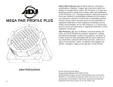
OVERVIEW
DMX
Out
Power
Out
Display
Screen
DMX
In
Mode
Button
Setup
Button
Up
Button
Down
Button
Power
In

10
SYSTEM MENU
MODE SETUP UP / DOWN DESCRIPTION
DMX Mode
dxxx d001 - d512 Set DMX address
Chxx
Ch04 4-channel DMX mode
Ch05 5-channel DMX mode
Ch06 6-channel DMX mode
Ch09 9-channel DMX mode
Ch10 10-channel DMX mode
blAc / LAst /
ProG
blAc Unit blacks out and switches all LEDs off if
DMX signal lost/interrupted
LAst Unit holds last state before signal was lost if
DMX signal lost/interrupted
ProG Unit runs internal programs if DMX signal
lost/interrupted
dr-x dr-0 ~ dr-4 Select dimmer curve
Dimmer
Mode
r.xxx r.000 ~ r.255 Adjust red intensity
G.xxx G.000 ~ G.255 Adjust green intensity
b.xxx b.000 ~ b.255 Adjust blue intensity
u.xxx u.000 ~ u.255 Adjust UV intensity
FS.xx FS.00 ~ FS.15 Adjust ash speed (FS.00 is off, FS.01 is
slowest, FS.15 is fastest)
Sound Mode
So.xx So.01 ~ So.16 Select from 16 built in sound modes
SJ-x SJ-1 ~ SJ-8 Adjust sensitivity of sound mode (SJ-1 is
least sensitive, SJ-8 is most sensitive)
Auto Run
Mode
AF.xx AF.01 ~ AF.16 Select from 16 dreaming modes
AJ.xx AJ.01 ~ AJ.16 Select from 16 jumping modes
A-JF
Select dreaming-jumping mode, in which the
unit will switch between the two modes in a
continuous cycle
SP.xx SP.01 ~ SP.16 Adjust the auto run speed
Static Color
Select Mode
CL.xx CL.00 ~ CL.64 Select static color (refer to Color Macros
Chart section of this manual for details)
FS.xx FS.00 ~ FS.15 Adjust ash speed (FS.00 is off, FS.01 is
slowest, FS.15 is fastest)
Other Mode
d.xxx don Display always on
doFF Display off
Ir.xx IRon IR remote function switched on
IRoF IR remote function switched off
Stnd / rEv Stnd Normal display orientation
rEv Inverted display orientation
dEFA Revert unit to factory default settings

11
OPERATING INSTRUCTIONS
System Menu: The display will lock after 30 seconds, press the MODE button for 3 seconds to
unlock.
Operating Modes:
The Mega Par Prole Plus has ve operating modes:
• Sound-Active mode - The unit will react to sound, chasing through the built in programs. There are
16 selectable sound active modes.
• Color Macro Mode - Choose from 64 color options.
• Auto Mode - Choose from 3 Auto Modes.
• RGB+UV Dimmer Mode - Choose one of the four colors to remain static or adjust the intensity of
each color to make your desired color.
• DMX control mode - This function will allow you to control each individual DMX traits using a stan-
dard DMX 512 controller.
DMX Mode:
Operating through a DMX controller gives the user the freedom to create custom programs tailored
to their own individual needs. This function also allows you to use your xtures as spot lights. 5 DMX
modes are available: 4 channel mode, 5 channel mode, 6 channel mode, 9 channel mode, and a 10
channel mode. Refer to the DMX Traits section of this manual for detailed information.
1. To run your xture in DMX mode, press the MODE button until “d.XXX” is displayed, where “XXX”
represents the currently selected DMX address. Use the UP or DOWN buttons to select your de-
sired DMX address, then press the SETUP button to select your DMX Channel mode.
2. Use the UP or DOWN buttons to scroll through the DMX Channel modes. The Channel modes are
listed below:
• “Ch04” = 4 Channel DMX Mode.
• “Ch05” = 5 Channel DMX Mode.
• “Ch06” = 6 Channel DMX Mode.
• “Ch09” = 9 Channel DMX Mode.
• “Ch10” = 10 Channel DMX Mode.
Plug in the xture via the XLR connections to any standard DMX controller.
No DMX State:
This setting denes the way the xture will behave in the event that the DMX signal is lost or inter-
rupted, or which operating mode the unit will return to when power is applied.
1. Plug the xture in and press the MODE button until “d.XXX” is displayed. “XXX” represents the
currently selected DMX address.
2. Press the SET UP button so that “nodn” is displayed. Use the UP and DOWN buttons to scroll
through the DMX states.
• “bLAC” (Blackout) - If the DMX signal is lost or interrupted, the unit will automatically go into
stand by mode.
• “LASt” (Last State) - If the DMX signal is lost or interrupted, the xture will stay in the last DMX
set up.
• “ProG” (Auto Run) - If the DMX signal is lost or interrupted, the unit will automatically go into
Auto Run mode.
3. Use the UP and DOWN buttons to nd your desired DMX state and press SET UP to conrm and
exit.

12
OPERATING INSTRUCTIONS
Dimmer Curve:
This is used to set the dimming curve used with DMX mode. Please refer to the Dimmer Curve
Chart section of this manual for detailed information.
1. Plug the xture in and press the MODE button until “DMX MODE” is displayed.
2. Press the SET UP button until “dr-X” is displayed. “X” represents the displayed dimmer curve (0-
4).
• 0 - Standard
• 1 - Stage
• 2 - TV
• 3 - Architectural
• 4 - Theatre
3. Press the UP or DOWN buttons to scroll through and select your desired dimming curve.
RGB+UV Dimmer Mode:
1. Plug the xture in and press the MODE button until the desired color mode is shown on the dis-
play. Options are as follows:
• “r.XXX” = Red dimming mode.
• “G.XXX” = Green dimming mode.
• “b.XXX” = Blue dimming mode.
• “u.XXX” = UV dimming mode.
2. Once the desired color option is shown on the display, press the UP and DOWN buttons to adjust
intensity.
3. Activate strobing by pressing the SET UP button to enter the Flash (strobe) mode. “FS.XX” will be
displayed, indicating that the unit is in Flash mode. The Flash can be adjusted between “FS.00”
(ash off) to “FS.15” (fastest ash).
Sound Mode:
When this mode is activated, the xture will react to sound and chase through the different colors.
1. Plug the xture in and press the MODE button until “SoXX” is displayed. “XX” represents the
sound active mode (1-16) that is currently selected. The xture will now change in response to
sound inputs.
2. Press the SET UP button to adjust the sound sensitivity. “SJ-X” should be displayed. Use the UP
or DOWN buttons to adjust the sensitivity. “SJ-1” is the lowest sensitivity, and “SJ-8” is the highest.
Auto Run Mode:
There are 3 Auto Run Modes to choose from: Color Fade, Color Change, and both modes running
together. The running speed is adjustable in all 3 modes.
1. Plug the xture in and press the MODE button until either “AFXX”, “AJXX”, or “A-JF” is displayed.
• AFXX = Color Fade mode, with 16 Color Fade modes to choose from. Use the UP or DOWN
buttons to scroll through the different modes.
• AJXX = Color Change mode, with 16 Color Change modes to choose from. Use the UP or
DOWN buttons to scroll through the different modes.
• A-JF = Both Color Fade and Color Change modes running.
2. After you have chosen your desired running mode, press the SET UP button until “SP.XX” is
displayed. Use the UP and DOWN buttons to set the running speed of the selected program, with
selectable values ranging from “SP.01” (slowest) to “SP.16” (fastest). Press the SET UP button to
return to your desired AutoRun Mode.

13
OPERATING INSTRUCTIONS
Static Color Mode:
1. Plug the xture in and press the MODE button until “CLXX” is displayed.
2. There are 64 colors to choose from. Select your desired color by pressing the UP and DOWN
buttons.
Activate strobing by pressing the SET UP button to enter the Flash (strobe) mode. “FS.XX” will be
displayed, indicating that the unit is in ash mode. The Flash can be adjusted between “FS.00” (ash
off) to “FS.15” (fastest ash).
LED Display On/Off:
To set the LED display to turn off after 10 seconds, press the MODE button until “don” is displayed,
then press the UP button to display “doff”. The display will turn off after 10s. The display can be
turned back on by pressing any button. To set the display press the MODE button until “dXX” is dis-
played. Use the UP or DOWN buttons to select either:
• “don” = LED display on at all times.
• “doFF” = LED display shuts off after 10 seconds.
ADJ LED RC2:
This function is used to activate or deactivate the ADJ LED RC2 (Remote Control). When this function
is activated, you can control the xture using the ADJ LED RC2. Refer to the ADJ LED RC2 section
of this manual for detailed infomation about controls and functions.
1. Plug the xture in and press the MODE button until “dXX” is displayed. “XX” represents either “on”
or “oFF”.
2. Press the SET UP button until “IrXX” is displayed. “XX” represents either “on” or “oF”.
3. Press the UP or DOWN buttons to either activate the remote function (On) or deactivate it (Off).
LED Display Inversion:
Flip the display 180° so that the display can be read when the unit is upside down.
1. Plug the xture in and press the MODE button until “dXX” is displayed. “XX” represents either “on”
or “oFF”.
2. Press the SET UP button until “Stnd” is displayed.
3. Press the UP or DOWN buttons to reverse the display 180°.
Default Running Mode:
When activated, all xture settings will return to their default factory values.
1. Plug the xture in and press the MODE button until “dXX” is displayed. “XX” represents either “on”
or “oFF”.
2. Press the SET UP button until “dEFA” is displayed.
3. Press the UP and DOWN buttons simultaneously, then press the MODE button to exit.

14
PRIMARY SECONDARY CONFIGURATION
This function will allows you to link units together to run in a Primary-Secondary set-up, in which one
unit will act as the controlling unit, and the others will react to the controlling unit’s built-in programs.
Any unit can act as a primary or as a secondary, but only one unit in a given system can be pro-
grammed to act as the primary.
Connections and Settings:
1. Daisy chain your units via the XLR connectors on the rear panel of each unit. Use standard XLR
data cables to link your units together. Remember that the male XLR connector is the input and
the female XLR connector is the ouput. The rst unit in the chain (primary) will use the female XLR
connector only, and the last unit in the chain will use the male XLR connector only.
2. Connect the rst secondary unit to the primary.
3. Set the primary unit to your desired mode of operation, then set the secondary unit(s) to the DMX
address setting. The secondary unit(s) will now follow the primary.

ADJ LED RC2
The ADJ LED RC2 infrared remote (sold seperately) controls many different functions and gives the
user complete control of this device. The controller must be aimed at the front of the xture, and max-
imum range is 30 feet. To use the ADJ LED RC2, the xture’s infrared receiver must rst be activated,
as explained in the Operation Instructions section of this manual. Please note that the unit will only
respond to remote inputs when the unit is in primary mode.
BLACKOUT - Press this button to blackout the xture.
PROGRAM SELECTION - This button will let you access color change mode, color fade mode, auto
run mode, or static color mode. Each press of this button will cycle to the next mode in sequence.
Once the desired mode has been selected, use the “+” or “-” buttons to scroll through the programs
or static colors. When using the auto run, color fade, or color change, press the Speed button, then
use the “+” or “-” to adjust the running speed. The unit’s LEDs will ash different colors to indicate the
selected mode, as follows:
• Red LEDs ash = Color Fade Mode.
• Green LEDs ash = Color Change Mode.
• Blue LEDs ash = Auto Run Mode.
• UV LED ashes = Static Color Mode.
FLASH - This button activates the strobe effect. You can control the ash rate by pressing the “+” and
“-” buttons. Press this button again to exit strobe mode.
SPEED - Press this button and use the “+” & “-” buttons to adjust the speed of the auto run, color
change, and color fade, or adjust the sound sensitivity in sound active mode.
DMX MODE - Press this button to scroll through DMX addressing, DMX Channel mode, DMX last
state setting, and dimming curves. When your desired menu/submenu is found, use the “+” & “-” but-
tons to scroll through the settings. Refer to the DMX Traits section of this manual for detailed infor-
mation.
SECD/SA (SOUND ACTIVE) - Use this button to toggle between sound active mode and secondary
mode. In sound active mode, use the “+” and “-” buttons to scroll through the 16 sound active pro-
grams. Press the Speed button to and use the “+” and “-” buttons to adjust the sound sensitivity. This
designates the xture as a secondary xture in a primary/secondary conguration.
SET ADDRESS - Press this button to set the DMX address, then use the number keys to enter in a
3-digit value for the DMX address. For example, to set the unit to a DMX address of 1, press the SET
ADDRESS button, then key in “0 - 0 - 1” using the number keys.
R G B A - Press the button representing the desired color, then press the “+” or “-” to adjust the
brightness. Please note that “A” selects UV dimmer mode.
“+” and “-” - Use these buttons to adjust the ash rate, speed of the built-in programs, sound sensi-
tivity, and program selection.
15

ADJ LED RC2
DMX MODE:
Operating through an DMX controller gives the user the freedom to create custom programs tailored
to their own individual needs. Follow the directions below to set your DMX channel mode and ad-
dress.
1. Before connecting to a DMX controller, please select your desired mode by pressing the DMX
Mode button, then using the “+” or “-” buttons to scroll through and select your desired DMX
Channel Mode. Set the mode before you address the xture.
2. After you have selected your mode, set the DMX address for the xture by pressing the “S” button.
The LEDs will ash 2-3 times and all the red LED’s will illuminate. Use the number buttons key in
a 3-digit DMX address. Please note that when setting the DMX address, an LED will glow each
time a number is pressed, then all LEDs will ash 2-3 times when you have set the DMX address
correctly.
3. Now you may connect the xture to any standard DMX controller via the XLR connections.
• All LEDs ash = 4-channel mode.
• Red LEDs ash = 5-channel mode.
• Green LEDs ash = 6-channel mode.
• Blue LEDs ash = 9-channel mode.
• UV LED ashes = 10-channel mode.
16

17
DMX SETUP
DMX-512: DMX is short for Digital Multiplex. This is a universal protocol used as a form of communication
between intelligent xtures and controllers. A DMX controller sends DMX data instructions from the
controller to the xture. DMX data is sent as serial data that travels from xture to xture via the DATA
“IN” and DATA “OUT” XLR terminals located on all DMX xtures (most controllers only have a DATA
“OUT” terminal).
DMX Linking: DMX is a language allowing all makes and models of different manufacturers to be
linked together and operate from a single controller, as long as all xtures and the controller are DMX
compliant. To ensure proper DMX data transmission, try to use the shortest cable path possible when
linking several DMX xtures. The order in which xtures are connected in a DMX line does not inuence
the DMX addressing. For example, a xture assigned a DMX address of 1 may be placed anywhere in
a DMX line: at the beginning, at the end, or anywhere in the middle. When a xture is assigned a DMX
address of 1, the DMX controller knows to send DATA assigned to address 1 to that unit, no matter
where it is located in the DMX chain.
Data Cable (DMX Cable) Requirements (For DMX Operation): This unit can be controlled via DMX-
512 protocol and features 5 selectable DMX modes. Please refer to the DMX Traits section of this
manual for detailed information. The DMX address can be set using the controls on the rear panel of
the unit. Your unit and your DMX controller require a 3-pin XLR connector for data input/output. We
recommend Accu-Cable DMX cables. If you are making your own cables, be sure to use standard 110-
120 Ohm shielded cable (This cable may be purchased at almost all pro lighting stores). Your cables
should be made with a male XLR connector on one end and a female XLR connector on the other. Also
remember that DMX cable must be daisy chained and cannot be split.

18
DMX SETUP
Special Note: Line Termination. When longer runs of cable are used, you may need to use a terminator
on the last unit to avoid erratic behavior. A terminator is a 110-120 ohm 1/4 watt resistor which is con-
nected between pins 2 and 3 of a male XLR connector (DATA + and DATA -). This unit is inserted in the
female XLR connector of the last unit in your daisy chain to terminate the line. Using a cable terminator
(ADJ part number Z-DMX/T) will decrease the possibilities of erratic behavior.
5-Pin XLR DMX Connectors: Some manufacturers use 5-pin DMX-512 data cables for DATA trans-
mission in place of 3-pin. 5-pin DMX xtures may be integrated into a 3-pin DMX line with a 5-pin to
3-pin adapter cable. These adapters are readily available at most electronics stores. Follow the chart
below for a proper conversion.
Notice: Be sure to the gures below when making your own cables. Do not use the ground lug on
the XLR connector. Do not connect the cable’s shield conductor to the ground lug or allow the shield
conductor to come in contact with the XLR’s outer casing. Grounding the shield could cause a short
circuit and erratic behavior.

19
DMX SETUP
DMX Addressing:
All xtures should be given a DMX starting address when using a DMX controller, in order to ensure
that the correct xture responds to the correct control signal. This digital starting address is the channel
number from which the xture starts to “listen” to the digital control signal sent out from the DMX
controller. The assignment of this starting DMX address is achieved by setting the correct DMX address
on the digital control display on the xture.
You can set the same starting address for all xtures or a group of xtures, or set different addresses for
each individual xture. Setting all xtures to the same DMX address will cause all xtures to react in the
same way; in other words, changing the settings of one channel will affect all the xtures simultaneously.
If you set each xture to a different DMX address, each unit will start to “listen” to the channel number
you have set, based on the quantity of DMX channels of each xture. That means changing the settings
of one channel will only affect the selected xture. For instance, when this unit is set to 6 Channel
mode, you should set the starting DMX address of the rst unit to 1, the second unit to 7 (1 + 6), the
third unit to 13 (1 + 6 + 6), the fourth unit to 19 (1 + 6 + 6 + 6), etc...
Channel Mode Unit 1 Address Unit 2 Address Unit 3 Address Unit 4 Address
4Ch 1 5 9 13
5Ch 1 6 11 16
6Ch 1 7 13 19
9Ch 1 10 19 28
10Ch 1 11 21 31

20
DMX TRAITS
CHANNEL DMX
VALUES FUNCTION
4Ch 5Ch 6Ch 9Ch 10Ch
11111000 - 255 Red, 0% to 100%
22222000 - 255 Green, 0% to 100%
33333000 - 255 Blue, 0% to 100%
44444000 - 255 UV, 0% to 100%
555
Shutter / Strobe
000 - 031 LED Off
032 - 063 LED On
064 - 095 Strobing, slow to fast
096 - 127 LED On
128 - 159 Strobe Pulse, slow to fast
160 - 191 LED On
192 - 223 Random Strobe, slow to fast
224 - 255 LED On
5666000 - 255 Master Dimmer, 0% to 100%
7 7
Program Selection Mode
000 - 051 Dimming Mode
052 - 102 Color Macro Mode
103 - 153 Color Change Mode
154 - 204 Color Fade Mode
205 - 255 Sound Active Mode
8 8
Color Macros / Programs / Sound Activity
000 - 255 Color Macro Mode, see Color Macro Chart section of this
manual
Color Change Program Mode
000 - 015 Color Change 1
016 - 031 Color Change 2
032 - 047 Color Change 3
048 - 063 Color Change 4
064 - 079 Color Change 5
080 - 095 Color Change 6
096 - 111 Color Change 7
112 - 127 Color Change 8
128 - 143 Color Change 9
144 - 159 Color Change 10
160 - 175 Color Change 11
176 - 191 Color Change 12
192 - 207 Color Change 13
208 - 223 Color Change 14
224 - 239 Color Change 15
240 - 255 Color Change 16
CONTINUED ON NEXT PAGE
/