

P
a
g
e 2
SAFETY
WARNING SYMBOLS AND DEFINITIONS
This is the sa
f
ety alert symbol. It is used to alert you to potential
personal injury hazards.
O
bey all sa
f
ety messages that
follow this s
y
mbol to avoid possible in
j
ur
y
or death.
I
ndicates a hazardous situation which, if not avoided,
will result in death or serious injury
.
I
ndicates a hazardous situation which, i
f
not avo
id
e
d
,
c
ou
ld
resu
l
t
i
n
d
eat
h
or ser
i
ous
i
n
j
ury
.
I
ndicates a hazardous situation which
,
i
f
not avoided
,
could
r
esul
t
i
n m
i
n
o
r
o
r m
ode
r
a
t
e
i
n
j
ur
y.
Add
resses pract
i
ces not re
l
ate
d
to persona
l
i
n
j
ury
.
IMPORTANT SAFETY INFORMATION
G
eneral Tool
S
a
f
ety Warning
s
Read all sa
f
ety warnings and instructions.
F
ailure to
f
ollow the warnings and instructions may result in electric shock,
f
ire and
/
or serious injury.
Save all warnings and instructions for future reference.
1
. KEEP GUARDS IN PLACE and in working order
.
2
. REM
O
VE ADJU
S
TIN
G
KEY
S
AND
W
REN
C
HE
S
. Form habit o
f
checking to
s
ee that keys and adjusting wrenches are
r
emoved from tool before turning it on
.
3. KEEP WORK AREA CLEAN.
Cluttere
d
a
r
eas
a
n
d
be
n
c
h
es
invit
e
acc
i
de
nt
s
.
4
.D
O
N’T U
S
E IN DAN
G
ER
O
U
S
ENVIR
O
NMENT.
Don’t use power tools in damp or wet locations,
or
e
xpose t
h
em to ra
i
n.
K
eep wor
k
area we
ll
li
g
h
te
d
.
5
. KEEP CHILDREN AWAY. All visitors should
be kept sa
f
e distance
f
rom work area
.
6
.
MAKE W
O
RK
S
H
O
P KID PR
OO
F with padlocks,
master switches, or by removing starter keys
.
7.
D
O
N’T F
O
R
C
E T
OO
L. It will do the job bette
r
and safer at the rate for which it was designed
.
8
. USE RIGHT TOOL. Don’t force tool or attachment
t
o do a job
f
or which it was not designed.

Pa
g
e
3
T
a
ble
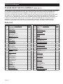
A
:
RE
C
O
MMENDED MINIMUM WIRE
G
AU
G
E
F
O
R EXTEN
S
I
O
N
C
O
RD
S
(
120 VOLT
)
NAME
P
LATE
AM
P
E
RE
S
(
at full load)
EXTENSION C
O
RD
LEN
G
T
H
0
– 6
1
8
1
61
6
1
4
6
.
1
–
10
18
16
14
12
10
.
1
–
12
16
16
14
12
12
.
1
–
16
1
4
12
D
o not use.
9
.
US
E PR
O
PER EXTEN
S
I
O
N
CO
RD. Mak
e
s
ure
y
our
extension cord is in good condition. When using
a
n extension cord, be sure to use one heavy
enou
g
h to carr
y
the current
y
our product will
d
r
a
w.
An
undersized cord will cause a dro
p
in line volta
g
e
resultin
g
in loss of power and overheatin
g
.
T
ab
l
e
A
shows the correct size to use dependin
g
on cord len
g
th and nameplate ampere
r
atin
g
.
If
i
n
d
oubt, use the next heavier
g
au
g
e.
The
s
maller the gauge number, the heavier the cord
.
1
0
. WEAR PR
O
PER APPAREL. Do not wea
r
l
oose clothin
g
,
gloves, neckties, rings, bracelets,
or other
j
ewelr
y
which ma
y
g
et cau
g
ht in movin
g
p
arts. Nonsli
p
footwear is recommended.
W
ea
r
p
rotective hair covering to contain long hair
.
11.
A
LWAY
S
US
E
S
AFETY
G
LA
SS
E
S
. Also use
face or dust mask if cuttin
g
operation is dust
y
.
Ever
y
da
y
e
y
e
g
lasses onl
y
have impact resistant
lenses, the
y
are NOT safet
y
g
lasses
.
12.
SECURE WORK. Use clam
p
s or a vise to
h
o
ld
work when practical. It’s safer than usin
g
y
ou
r
h
and and it
f
rees both hands to o
p
erate tool.
13
.
DO
N’T
O
VERREA
C
H.
Keep proper
f
ooting and balance at all times.
1
4.
M
AINTAIN T
OO
L
S
WITH
C
ARE. Keep
t
ools shar
p
and clean for best and safest
p
erformance. Follow instructions fo
r
lubricating and changing accessories.
1
5
.
D
ISCONNECT TOOLS before servicin
g
;
when changing accessories, such as
blades, bits, cutters, and the like.
16.
R
EDUCE THE RISK OF UNINTENTIONA
L
S
TARTING. Make sure switch is in
o
ff position before plu
gg
in
g
in
.
17.
US
E RE
CO
MMENDED A
CC
E
SSO
RIE
S
.
C
onsult the owner’s manual for recommended
accessories. The use o
f
im
p
ro
p
er accessories
ma
y
cause risk of in
j
ur
y
to persons
.
18.
N
EVER
S
TAND
O
N T
OO
L.
Serious in
j
ur
y
could occur if the tool is tipped o
r
i
f the cuttin
g
tool is unintentionall
y
contacted.
19
.
C
HE
C
K DAMA
G
ED PART
S
. Be
f
ore
f
urther use
of the tool, a
g
uard or other part that is dama
g
ed
should be care
f
ull
y
checked to determine that
it will operate properly and per
f
orm its intended
function – check for alignment of moving parts,
bindin
g
o
f
movin
g
parts, breaka
g
e o
f
parts,
mounting, and any other conditions that may
affect its operation. A
g
uard or other part that is
d
ama
g
e
d
s
h
ou
ld
b
e proper
ly
repa
i
re
d
or rep
l
ace
d.
20
.
D
IRE
C
TI
O
N
O
F FEED.
Feed work into a blade or cutter a
g
ainst the
direction o
f
rotation o
f
the blade or cutter only
.
21.
NEVER LEAVE T
OO
L R
U
NNIN
G
U
NATTENDED.
TU
RN P
O
WER
O
FF
.
D
o
n
’
t l
ea
v
e
t
oo
l
unt
il
i
t comes to a com
pl
ete sto
p
.

P
a
g
e 4
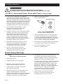
Grounding Instructions
T
O
P
R
EVENT ELEC
T
RIC SH
O
C
K AND DEATH FROM I
N
C
ORR
E
C
T
G
ROUNDING WIRE CONNE
C
TION READ AND FOLLOW THESE INSTR
U
CTIONS:
1
10-120 V~ Grounded Tools: Tools with Three
P
rong
P
lugs
1
.
I
n the event o
f
a mal
f
unction or breakdown,
grounding provides a path o
f
least resistance
f
o
r
electric current to reduce the risk of electric shock.
Thi
s too
l
i
s equ
i
ppe
d
w
i
t
h
an e
l
ectr
i
c cor
d
h
av
i
ng an
equ
i
pment-groun
di
ng con
d
uctor an
d
a groun
di
ng
pl
ug.
Th
e p
l
ug must
b
e p
l
ugge
d
i
nto a matc
hi
ng
o
ut
l
et t
h
at
i
s proper
l
y
i
nsta
ll
e
d
an
d
groun
d
e
d
i
n
accor
d
ance w
i
t
h
a
ll
l
oca
l
co
d
es an
d
or
di
nances.
2
. Do not modif
y
the plu
g
provided – if it will
n
ot
f
it the outlet, have the proper outlet
i
nstalled b
y
a qualified electrician.
3
.
I
mproper connection of the equipment-
g
roundin
g
conductor can result in a risk of electric shock.
The conductor with insulation having an oute
r
s
urface that is
g
reen with or without
y
ellow
s
tripes is the equipment-
g
roundin
g
conductor.
If
repair or replacement o
f
the electric cord o
r
p
lu
g
is necessar
y
, do not connect the equipment
-
g
roundin
g
conductor to a live terminal.
4
.
C
heck with a quali
f
ied electrician or service
p
ersonnel i
f
the grounding instructions are
n
ot completely understood, or i
f
in doubt as
to whether the tool is properly grounded.
5
. Use onl
y
3-wire extension cords that
h
ave 3-prong grounding plugs and 3-pole
r
eceptacles that accept the tool
’
s plug
.
6
.
Repair or replace damaged o
r
worn cor
d
i
mme
di
ate
l
y
.
Grounding
P
i
n
12
5
V
~
3
-
P
rong
P
lug
a
n
d
O
utle
t
(
for up to 125 V~ and up to 15 A)
7.
This tool is intended
f
or use on a circuit that has
a
n
ou
t
le
t t
ha
t
looks
like
t
he
o
n
e
illus
tr
a
t
ed
abo
v
e
in 12
5
V
~
3-
P
r
on
g
P
l
u
g
a
n
d
Out
l
et
. Th
e
too
l h
as
a groun
di
ng p
l
ug t
h
at
l
oo
k
s
lik
e t
h
e p
l
ug
ill
ustrate
d
abo
v
e
i
n12
5
V~
3
-
P
r
on
g
P
l
ug an
d
Out
l
et
.
8
.
Th
e out
l
et must
b
e proper
l
y
i
nsta
ll
e
d
an
d
groun
d
e
d
i
n
acco
r
da
n
ce
w
i
t
h
all
codes
a
n
d
o
r
di
n
a
n
ces.
9
.
D
o not use an a
d
a
p
ter to connect
t
hi
s
t
oo
l t
o
a
d
iff
e
r
e
nt
ou
tl
e
t
.
Sa
n
de
r Safety Warning
s
Fo
r
Y
our Own Safety Read Instruction
Y
Y
Manual Be
f
ore
O
peratin
g
S
ander
1
.
W
ear e
y
e protection
.
2
. Support workpiece with miter
g
au
g
e,
backstop, or
worktable.
r
3. Maintain 1/16 inch maximum clearance
b
etween ta
bl
e an
d
san
di
n
g
b
e
l
t or
di
sc.
4
.
A
void kickback by sanding in accordance
w
i
t
h
t
h
e
di
rect
i
ona
l
arrows.
5
. The backstop is a fence near the surface that
h
elps the operator maintain control o
f
the
workpiece and prevents the workpiece from bein
g
p
ulled into the machine. For
s
afet
y
, it must be
adjusted very close to the sanding sur
f
ace.
6
.
The worktable is the surface mounted close to
the sanding sur
f
ace that the operator rests the
workpiece a
g
ainst to prevent it from bein
g
pulled
ad
j
usted ver
y
close to the sandin
g
surface.
7.
Th
e san
di
ng
b
e
l
t
i
s
d
es
i
gne
d
to rotate
d
own towar
d
s
the table while the disc rotates both up
f
rom the
t
able and down towards the
t
able. Sand on the
belt with the workpiece in
f
ront o
f
the backstop
and/or table.
S
an
d
on
l
y on t
h
e
d
ownwar
d
mov
i
ng
s
urface of the disc - sandin
g
on the upward
moving sur
f
ace may result in the workpiece
b
e
i
ng t
h
rown up an
d
towar
d
s t
h
e operator
.
8
.
R
emove Safet
y
Ke
y
when the Switch is
t
urned o
ff
. Do not leave the
S
a
f
ety Key in
t
he Switch when the tool is not in use
.

Pa
g
e
5
9
.D
O
N
O
T
O
P
ERATE WITH AN
Y
GUARD
Y
DI
S
ABLED, DAMA
G
ED,
O
R REM
O
VED
.
M
ov
i
ng
g
uards must move freely and close instantly
.
1
0
.Th
e
use
o
f
accesso
ri
es
o
r
a
tt
ac
hm
e
nt
s
n
o
t
recommended by the manufacturer may
result in a risk of injury to persons.
11. When servicin
g
use onl
y
identical replacement parts
.
12.
Only use safety equipment that has been approved
b
y
an appropriate standards a
g
enc
y
. Unapproved
s
afet
y
equipment ma
y
not provide adequate
p
rotection. Eye protection must be ANSI-approved
a
nd breathin
g
protection must be NIOSH-approved
for the s
p
ecific hazards in the work area.
13. Stay alert, watch what you are doing and use
common sense when operatin
g
a power tool.
D
o
not use a power tool while
y
ou are tired or
under the influence of dru
g
s, alcohol or medication.
A
m
oment of inattention while operating power
tools ma
y
result in serious personal in
j
ur
y.
14.
I
ndustrial applications must
f
ollow
OS
HA guidelines
.
1
5
.
M
a
i
nta
i
n
l
a
b
e
l
s an
d
name
pl
ates on
t
h
e
t
ool.
These carr
y
important safet
y
information.
If
u
nreadable or missing, contact
Harbor Freight Tools for a replacement
.
16
.
A
void unintentional starting.
Prepare to be
g
in work before turnin
g
on the tool
.
1
7.
P
eo
pl
e w
i
t
h
p
acema
k
ers s
h
ou
ld
consu
l
t t
h
e
i
r
p
h
y
sician
(
s
)
be
f
ore use. Electroma
g
netic
f
ields in
c
l
ose prox
i
m
i
ty to
h
eart pacema
k
er cou
ld
cause
p
acemaker inter
f
erence or
p
acemaker
f
ailure.
18
.
W
ARNIN
G
:
S
ome dust created by powe
r
san
di
ng, saw
i
ng, gr
i
n
di
ng,
d
r
illi
ng, an
d
ot
h
e
r
c
onstruct
i
on act
i
v
i
t
i
es, conta
i
ns c
h
em
i
ca
l
s
k
nown [to the
S
tate o
f
C
ali
f
ornia] to cause
c
ancer, birth de
f
ects or other reproductive harm.
S
ome exam
p
les o
f
t
h
ese
c
h
e
mi
ca
l
s
a
r
e
:
or other masonry product
s
Arsenic and chromium from
chemicall
y
tr
ea
t
ed
lu
m
be
r
1
9
. Your risk from these ex
p
osures varies,
d
ependin
g
on how o
f
ten
y
ou do this
ty
pe
of
work.
To
reduce
y
ou
r
e
x
p
osure to these chemicals:
work
i
n
a
well ventilated area, and
work with approved safet
y
equipment, such
as those dust masks that are specially
desi
g
ned to filter out microscopic particles.
(C
ali
f
ornia Health
&
S
a
f
ety
C
ode
§
25249.5, e
t
se
q.
)
20
.
W
ARNING: Handlin
g
the cord on this product will
e
xpose
y
ou to lead, a chemical known to the State
o
f
C
ali
f
ornia to cause cancer
,
and birth de
f
ects o
r
other reproductive harm. Wash hands a
f
ter handling.
(California Health & Safety Code § 25249.5, e
t
se
q.
)
21
.
T
he warnings, precautions, and instructions
d
iscussed in this instruction manual cannot cover all
possible conditions and situations that ma
y
occur.
It must be understood by the operator that
co
mm
o
n
se
n
se
a
n
d
cau
ti
o
n
a
r
e
f
ac
t
o
r
s
w
hi
c
h
cannot
b
e
b
u
il
t
i
nto t
hi
s
p
ro
d
uct,
b
ut must
b
e supp
li
e
d
b
y t
h
e operator
.
Vibration Safet
y
This tool vibrates during use. Repeated o
r
lon
g
-term exposure to vibration ma
y
cause
temporar
y
or permanent ph
y
sical in
j
ur
y
,
p
articularly to the hands, arms and shoulders. To
reduce the risk of vibration-related in
j
ur
y:
1.
A
n
y
one usin
g
vibratin
g
tools re
g
ularl
y
or for an
extended period should first be examined b
y
a
doctor and then have regular medical check
-
up
s
to ensure medical problems are not bein
g
caused
or worsened from use. Pregnant women o
r
p
eo
p
le who have im
p
aired blood circulation to
the hand, past hand in
j
uries, nervous s
y
stem
disorders, diabetes, or Raynaud
’
s Disease should
n
ot use this tool. If you feel any medical or
ph
y
sical s
y
mptoms related to vibration
(
such as
tin
g
lin
g
, numbness, and white or blue fin
g
ers
)
,
s
eek medical advice as soon as possible.
2.
D
o not smoke during use. Nicotine reduces
t
he blood suppl
y
to the hands and fin
g
ers,
increasin
g
the risk of vibration-related in
j
ur
y.
3
.
U
se tools with the lowest vibration when there
i
s a choice between di
ff
erent processes
.
4.
Include vibration-free periods each da
y
of work
.
5
.
G
rip tool as lightly as possible (while still keeping
6.
To reduce vibration
,
maintain the tool as
e
xplained in this manual. If any abnormal
vibration occurs, stop use immediatel
y.
S
AVE THE
S
E IN
S
TR
U
C
TI
O
N
S.

P
a
g
e 6
Specifications
El
ectr
i
ca
l
R
at
i
n
g
12
0
V
~
/
60
Hz
/
3
.
5A
Belt Siz
e
4" W x
36
" L
Disc
S
iz
e
6"
Max. Speed 1819 RPM (Disc
)
1185 FPM (Belt)
Setup - Before Use:
Read
t
h
e
E
NTIRE
I
M
P
O
RTANT
S
AFE
T
Y
INFORMATION
Y
section at the be
g
innin
g
of this
manual includin
g
all text under subheadin
g
s therein before set up or use of this product.
TO
P
REVENT SERIOUS INJUR
Y
R
R
FROM A
Y
C
C
I
DENTA
L
O
P
E
RATI
O
N:
Tu
rn
t
h
e
P
o
w
e
r
S
wi
tc
h
o
f
t
h
e
too
l
o
f
f
and unplug the tool from its
f
e
l
ect
ri
cal
out
l
et
b
e
f
ore per
f
ormin
g
an
y
procedure in this section.
N
ote
:
For additional information regarding the parts listed in the following pages,
r
e
f
er to the Assembl
y
Dia
g
ram near the end o
f
this manual
.
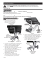
Assembly/Mountin
g
Feet
P
l
acement
1
.
C
are
f
ully set the Belt
/
Disc
S
ander on its side
.
2
. Press Rubber Feet
(
28
)
over the fou
r
corner li
p
s o
f
the Base.
S
ee Figur
e
A.
Rubber Feet
(
28
)
Fi
g
ur
e
A
Mounting Backing Disc
gg
1.
S
et the Belt
/
Disc
S
ander on its
f
ee
t
.
2.
Slide the Backin
g
Disc
(
5
)
onto the Drive Axle
(
54
)
.
The
S
et
S
crew
(
6
)
must
f
ace the
f
lat sur
f
ace
of
the Drive Axle
(
54
)
.
S
ee Fi
g
ur
e
B
.
Figur
e
B
D
rive Axle
(
54
)
Backin
g
Disc
(
5
)
3
. Tighten the
S
et
S
crew
(
6
)
securely
.
227541

P
a
g
e 7
Mounting Fence
g
1
. The Fence
(
63
)
f
its across the top o
f
the
s
andin
g
belt to prevent workpiece from
m
ov
i
ng to t
h
e rear w
h
en san
di
ng.
2
.
A
lign two Tabs on the Fence (63) with two
Holes on the top of the Bel
t
E
n
d
Guar
d
(58).
Pl
ace
Fe
n
ce
t
abs
u
n
de
rn
ea
th th
e
Belt En
d
G
uar
d
(58). Insert
t
wo Machine
S
crews
through Flat
W
ashers and into Holes. Thread
Machine Screws into the Tabs on the Fenc
e
(
63
)
.
Note: Us
e
Flat Washer
s
b
etween screw heads
a
nd Bel
t
En
d
Guard
(
58
)
. See Fi
g
ur
e
C
.
3
. Bolt the Fence
(
63
)
to the
Belt
S
u
pp
or
t
H
ousin
g
(52) using Bolt (32),
Flat
W
ashe
r
(
26
)
, and Lock Washer
(
27
).
Figur
e
C
Fence
(
63
)
T
abs (not shown) are underneath Bel
t
E
n
d
G
uard (58)
where Machine
S
crews are shown.
M
achine Screws
F
unct
i
on
s
S
wi
tc
h wi
t
h
S
afet
y
Ke
y
Supportin
g
S
h
a
f
t
An
g
le Ad
j
ustin
g
Kn
ob
Tabl
e
M
iter Gaug
e
Sanding Belt
Sanding
Di
s
c
F
enc
e
Be
l
t
T
e
n
s
i
o
n
H
an
dle
B
e
l
t
A
lignment
K
no
b
Fig
ur
e
D
Safety Switch
y
I
nsert the Safety Key into the Switch. This “Key” is a safety precaution and should remain in the Switch during use
and be removed after Switch
(
31
)
is turned off and/or an
y
time the Belt/Disc Sander is left unattended or in stora
g
e
.

P
a
g
e 8
Operating Instructions
R
ea
d
t
h
e
ENTIRE
IM
P
O
RTANT
S
AFE
T
Y
INFORMATION
Y
section at the beginning o
f
this
m
anual including all text under subheadings therein be
f
ore set up or use o
f
this product.
Tool Set U
p
TO
P
REVENT SERIOUS INJUR
Y
R
R
FROM A
Y
C
C
I
DENTA
L
O
P
E
RATI
O
N:
T
urn the
P
ower Switch of the tool of
f
and unplug the tool from its
f
e
lectrica
l
outle
t
b
efore performin
g
an
y
procedure in this section.
TO
P
REVENT SERIOUS INJUR
Y
R
R
:
DO NOT O
P
E
RATE WITH AN
Y
GUARD DISABLED, DAMAGED, OR
Y
REMOVED
.
Mounting Table for Use as Disc Sander
g
N
O
TE: The Table
(
69
)
may be used as support
f
or both horizontal and vertical applications.
1
.
I
nsert the end of Table Bar (72)
with Pivot Indicato
r
(
70
)
into the
Bar
H
older
(
74
)
.
S
ee Figur
e
E
.
T
able
(
69
)
B
ar Holder
(
74
)
P
ivot
Indicator
(
70
)
A
n
g
le
Ad
j
ustin
g
K
nob
(
75
)
Flat Washer
(
26
)
Tighten two
S
et
Screws (6)
Table Bar (72)
)
)
)
)
F
i
g
ur
e
E
2
.
I
nsert free end of Table Bar
(
72
)
into two Mountin
g
S
upports on bottom o
f
Table
(
69
)
. Tighten the
two Set Screws. See Fi
g
ur
e
E on pa
g
e 8.
3. Mount the Pivot Indicator (70) tab to the
Tabl
e
(
69
)
usin
g
a Hex Bolt
(
71
)
, Flat Washe
r
(
26
)
and Lock Washer
(
27
)
. See Fi
g
ur
e
F
.
4
. Mount Pivot Indicator
(
70
)
to the Bar H
o
l
der
(
74
)
usin
g
the An
g
le Ad
j
ustin
g
Kno
b
(
75
)
and Flat Washe
r
(
26
)
. Fin
g
er ti
g
hten.
See Fi
g
ur
e
E
a
n
d
Fi
g
ur
e
F
.
5. Ti
g
hten all fasteners. Make sure the
Piv
ot
Indicator
(
70
)
operates smoothl
y
when
the An
g
le Ad
j
ustin
g
Knob
(
75
)
is loosened
.
)
,
r
(
26
)
ck
2
7
)
Figure
F
6.
Slide the Supportin
g
Shaft
(
76
)
into Bar Holde
r
(
74
)
.
A
lign the
f
lat
f
ace o
f
the
S
upporting
S
ha
f
t with
S
e
t
S
crews and tighten securely.
S
ee Figur
e
G
.
7.
Slide the Supportin
g
Shaft
(
76
)
into the hole
o
n side o
f
Machine Body
(
33
)
and tighten
Bolt
(
32
)
. See Fi
g
ur
e
D
on pa
g
e 7
.
S
upporting
S
ha
f
t
F
lat
S
ide (76)
B
ar Holder
(
74
)
Fi
gure
G

P
a
g
e
9
Mounting Table for Use as Belt Sander
g
N
O
TE: The Table
(
69
)
may be used
f
or both
h
or
i
zonta
l
an
d
vert
i
ca
l
operat
i
ons.
1
. Remove Table
f
rom Machine Body
(
33
)
by loosening
Bolt (32) and sliding Supporting Shaft (76) out.
Fi
gur
e
H
Supporting
R
od (23)
Outer
P
ull
ey
C
over (9)
Di
sc
C
over
(
8
)
Nut (22
)
2.
S
et Belt
/
Disc
S
ander in vertical position by
loosening both Nuts (22). Raise the Belt Support
Housing
(
52
)
. When it is vertical, wrench tighten
both Nuts (22) securely to prevent the Belt Support
Housing (52) from slipping. See Figur
e
H
.
3
.
I
nsert Supportin
g
Shaft
(
76
)
into the hole facin
g
t
he belts and tighten Bolt (32) against flat side
o
f Supporting Shaft (76). See Figur
e
I
.
F
igure
I
Table (69)
Belt Sander
(
62
)
Leveling the Table
g
N
O
TE: For these instructions and
“G
eneral
O
perating Instructions” on
f
ollowing pages, re
f
er
t
o
Fi
gur
e
C
on page
7
o
f
this manual.
1
. Loosen the Angle Adjusting Knob
(
75
)
on the
Pivot Indicator
(
70
)
. Place a combination
s
quare
(
not supplied
)
on the Table
(
69
)
so that
t
h
e com
bi
nat
i
on square touc
h
es t
h
e san
di
ng
disc. I
f
the Table is 90
°
to the sanding disc,
t
h
e ta
bl
e
i
s
l
eve
l
.
Al
ways ma
i
nta
i
n a max
i
mum
o
f
1
/
16" clearance between the Table and
t
h
e
S
andin
g
Di
sc.
Ti
g
h
ten t
h
e
A
ng
l
e
Adj
ust
i
ng
K
no
b.
2.
If
the Table is not 90
°
to the sanding disc pad,
l
oosen t
h
e
A
ng
l
e
Adj
ust
i
ng
K
no
b
an
d
t
il
t t
h
e
T
a
bl
e unt
il
i
t
i
s square w
i
t
h
t
h
e san
di
n
g
di
sc.
Ti
g
h
ten t
h
e
A
ng
l
e
Adj
ust
i
ng
K
no
b.
3
. Loosen
S
crew
(
29
)
holding the Angle Pointer
(
73
)
and adjust it to point to 90
°
. Tighten the
S
crew
.
Adjusting the Sanding Belt Tracking
jg g g
1
. With the Belt
/
Disc
S
ander turned o
ff
,
manually move the
S
anding Belt.
2.
If
the belt starts moving to the side o
f
ei
t
h
er ro
ll
er,
i
t nee
d
s to
b
e a
dj
uste
d.

P
a
g
e 10
3
. Turn the Belt Adjustment Knob
(
49
)
until
the belt rides the center o
f
the Rear
Roller
(
56
)
and the Front Roller
(
44
).
4.
Move the
S
anding Belt manually a
f
ter
a
dj
ustment to assure proper a
li
gnment
.
Mounting Sanding Discs
gg
NOTE: Before usin
g
the Sandin
g
Disc the first
t
ime, wipe down the Backing Disc with denatured
a
lcohol (shellac thinner). This will clean the surface,
l
eave no res
id
ue an
d
assure a secure
b
on
d
.
1
. Remove the Table
(
69
)
if it is mounted
i
n front of the Sandin
g
Disc.
2.
Peel off old Sandin
g
Disc
.
3
.
A
li
g
n perimeter of new Sandin
g
Disc
o
ver the Backing Disc (5) and press
firml
y
onto the Backin
g
Disc.
Workpiece and Work Area
S
et U
p
1
. Designate a work area that is clean and well
li
t.
Th
e wor
k
area must not a
ll
ow access
b
y
children or pets to prevent distraction and injury
.
2
. Route the power cord along a sa
f
e route to reach
t
h
e wor
k
area w
i
t
h
out creat
i
n
g
a tr
i
pp
i
n
g
h
azar
d
o
r
exposin
g
the power cord to possible dama
g
e. The
p
ower cord must reach the work area with enough
extra len
g
th to allow
f
ree movement while workin
g.
3
.
S
ecure loose workpieces using a vise or clamps
(
not included
)
to prevent movement while working
.
4
.
T
here must not be ob
j
ects, such as utilit
y
lines,
nearby that will present a hazard while working
.
G
eneral
O
perating Instructions
1
. Make sure that the
S
witch is
in
th
e
off
-
f
f
p
osition,
t
h
en p
l
u
g
i
n t
h
e too
l
.
2
.
I
nsert Safet
y
Ke
y
into Switch
.
3
. Make sure nothin
g
is contactin
g
the Sandin
g
Disc or Belt
,
then turn on the Switch.
4.
W
hen usin
g
the Disc Sander, onl
y
use the LEFT
s
ide of the Sandin
g
Disc
(
as
y
ou face it
)
to sand.
The Sandin
g
Disc turns counterclockwise and
usin
g
the ri
g
ht side could cause kickback.
5
.
U
se two hands and hold workpiece securel
y
against the fence/table at all times. Press the
workpiece a
g
ainst the belt/disc to start sandin
g
.
Keep the workpiece movin
g
for a better finish.
6.
A
fter use
,
turn off the tool
,
remove the
Safet
y
Ke
y
from the Switch, and disconnect
from the power suppl
y
. Clean and store the
t
oo
l in
doo
r
s
ou
t
o
f
c
hil
d
r
e
n'
s
r
eac
h
.

Pa
g
e 1
1
Maintenance and Servicing
P
r
ocedures not speci
f
ically explained in this manual must
b
e per
f
ormed only by a quali
f
ied technician.
TO
P
REVENT SERIOUS INJUR
Y
R
R
FROM A
Y
C
C
IDENTAL
O
P
E
RATI
O
N:
T
urn t
h
e
P
ower
S
witch o
f
the tool o
ff
and unplug the tool from its
f
el
ectr
i
ca
l
out
l
e
t
b
e
f
ore per
f
orming any procedure in this section.
TO
P
REVENT SERIOUS INJUR
Y
R
R
FROM
Y
T
OOL
FAI
L
URE:
D
o not use
d
amage
d
equ
i
pment.
If
ab
norma
l
no
i
se or v
ib
rat
i
on
o
ccurs, have the problem corrected be
f
ore
f
urther use
.
C
l
eaning, Maintenance, and Lubrication
1. BEF
O
RE E
A
C
H U
S
E
,
inspect the general
condition o
f
the tool.
C
heck
f
or:
loose hardware,
m
isali
g
nment or bindin
g
of movin
g
parts,
cracked or broken parts,
d
ama
g
ed electrical wirin
g
, and
any other condition that may
a
ff
ect its sa
fe
o
peration.
2
.AFTER U
S
E, turn o
ff
the tool, remove the
S
a
f
et
y
Ke
y
f
rom the
S
witch, and disconnect
i
ts power supply. Then, wipe external
s
urfaces of the tool with clean cloth.
3
.
A
Dust Port
(
59
)
is located on the bottom o
f
the
Lower
G
uard Plate
(
60
)
. It is held in place with a
Screw (61) and can be removed for vacuuming
c
ollected dust and sanding residue. Replace the
D
ust Port a
f
ter cleaning and tighten
S
crew
.
4.
A
pply a light coat of paste wax to the Table
t
o make feedin
g
material easier
.
5
.
U
se compressed air to blow dust and
debris from the
S
ander and Motor
.
6.
The Bearin
g
s on this Sander are sealed
an
d
d
o not requ
i
re
l
u
b
r
i
cat
i
on.
7.
W
ARNIN
G
! I
f
the supply cord o
f
this
p
ower too
l
i
s
d
amage
d
,
i
t must
b
e rep
l
ace
d
o
nl
y
b
y
a quali
f
ied service technician
.

P
a
g
e 12
S
anding Belt Replacemen
t
1
. Push the Belt Tension Handle (50)
f
orward to loosen the belt.
2
. Remove Upper Guard Plate (58) by
unscrewing four Screws (7).
3. Remove the Lower Guard Plate (60) by
unscrewing the four Screws (7) that hold
i
t to the Belt Support Housin
g
(
52
)
.
4.
S
lide the old
S
andin
g
Belt o
ff
the
R
ear
R
oller
(
56
)
and Front Roller
(
44
).
5. Replace with a 4" X 36" Sandin
g
Belt with the
correct grit
f
or the project you are working on.
N
ote:
Th
e
l
ar
g
er t
h
e
g
r
i
t num
b
er, t
h
e sma
ll
e
r
the
g
rain. Use small numbered
g
rits for cuttin
g
and lar
g
er for smoothin
g
and finishin
g
.
6
.
Slide a new Sanding Belt onto
F
ront an
d
R
ear
R
o
ll
ers
.
7.
R
eplace the Lower Guard Plate and
t
ighten the four Screws securely
.
8
.
R
eplace the Upper Guard Plate
and tighten the four Screws
.
9
. Push the Belt Tension Handle to
t
he rear to ti
g
hten the belt.
10. Before usin
g
, manuall
y
check the new
belt for ali
g
nment. See instructions in the
“G
eneral
O
perating” section o
f
this manual
.
V-Belt Replacemen
t
1
. Remove Set Screws
(
6
)
and
p
ull
off
Backing Disc
(
5
).
2
. Remove
f
our
S
crews
(
11
)
and Washer
s
(
10
)
f
rom
O
uter Pulley
C
over
(
9
)
.
3
.
O
nce the
O
uter Pulley
C
over is removed,
the V-Belt
(
12
)
is accessible
.
4
. Remove the V-Belt using a
f
lat screwdrive
r
(
not supplied
)
. Place the tip of the screwdrive
r
b
etween the Motor Pulley
(
13
)
and the V-Belt
w
hil
e turn
i
n
g
t
h
e
V
-
B
e
l
t
by
h
an
d
.
As
i
t turns,
the V-Belt will ride u
p
and out of the Moto
r
Pulley groove.
O
nce o
ff
the Motor Pulley, li
f
t
the V-Belt off of the Spindle Pulle
y
(
14
).
5
. Place the new V-Belt
(
12
)
onto the Spindle
Pulley, by using a
f
lat screwdriver
(
no
t
supplied
)
as a wed
g
e. Turn the
S
pindle Pulle
y
and
ride the new V-Belt onto the Motor Pulle
y.
6.
R
eplace Outer Pulle
y
Cover.
T
ighten
S
crews and Washers
.
WARNIN
G
!If the supply cord of this
power tool is dama
g
ed, it must be replaced
o
nl
y
b
y
a qualified service technician.
V
-
B
e
l
t
T
ens
i
on
i
n
g
1
. Remove
S
et
S
crews
(
6
)
and
p
u
ll
off
Backing Disc
(
5
).
2
. Remove
f
our
S
crews
(
11
)
and Washer
s
(
10
)
f
rom
O
uter Pulle
y
C
over
(
9
)
.
3. Loosen four motor mount Nuts
(
22
)
and slide the
Motor
(
40
)
f
urther
f
orward towards Front Roller
(
44
)
,
makin
g
sure to pull evenl
y
on the motor.
W
hile holdin
g
the Motor in its current
p
osition, ti
g
hten the Nuts.
4.
Place a straight edge on the
f
aces o
f
th
e two pu
ll
eys to ascerta
i
n a
li
gnment.
C
ontact
s
ur
f
aces o
f
t
h
e pu
ll
eys an
d
t
h
e stra
i
g
h
t
edge must
f
ully touch. Fully tighten the Nuts
.
5
.
R
eplace Outer Pulle
y
Cover and
t
i
g
hten Screws and Washers.
R
eplace
B
ackin
g
Dis
c
a
nd
t
i
g
hten
S
et
S
crews
.

Pa
g
e 1
3
T
rou
bl
es
h
oot
i
n
g
P
r
ob
l
em
P
oss
i
b
l
e
C
auses
Likel
y
Solution
s
Belt
/
Disc
S
ande
r
does not turn o
n
1.
N
ot plugged in.
2
.
N
o power at outlet.
3.
S
afety Key not inserted into Switch
.
4
.
S
witch is not turned “ON”.
1.
P
lug in
S
ander
.
2
. Check power at outlet and/or circuit breaker
.
3.
I
nsert Safety Key into Switch
.
4
. Turn on the Switch
.
M
otor s
l
ows
when sandin
g
1
.
V
-
B
e
l
t too t
i
g
h
t
.
2
.
A
ppl
y
in
g
too much pressure
while sandin
g
1
. Have the V-Belt adjusted by a quali
f
ied technician
.
2
. Use less
p
ressure.
Wood burns
w
hil
e san
di
n
g
1
.
S
anding disc or belt may be
l
oa
d
e
d
w
i
t
h
di
rt or
d
e
b
r
i
s.
2
.
T
oo much pressure
.
1
. Clean or replace disc or belt using
i
nstruct
i
ons
i
n t
hi
s manua
l
.
2
. Use less pressure.
F
ollow all sa
f
ety precautions whenever diagnosing or servicing
the tool. Disconnect power supply be
f
ore service.

P
a
g
e 14
P
a
r
t
Descri
p
tion
p
Q
t
y
y
1
Screw M4 X 12
9
2
Flat Washe
r
27
3
Front
C
ove
r
1
4
S
andin
g
Disc
g
1
5
B
ackin
g
Disc
g
1
6
S
crew M
8
X
8
6
7
S
et
S
crew M4 X
8
14
8
Disc
C
ove
r
1
9
O
uter Pulle
y
C
ove
r
y
1
1
0
W
as
h
er
1
6
11
S
crew M4 X
8
6
12
V
-
B
e
lt
1
1
3
M
otor
P
u
ll
e
y
y
1
14 S
p
indle Pulle
y
py
1
1
5
S
crew M
8
X
6
2
1
6
B
olt M
6
X 12
6
17
L
oc
k
W
as
h
e
r
7
18 Fl
a
t W
as
h
er
7
19
S
crew M
5
X 2
0
3
20
Inner Pulle
y
C
ove
r
y
1
2
1
Sp
acer
p
1
22
Nut
8
6
2
3
S
u
pp
ortin
g
Ro
d
pp g
1
2
4
Nu
t
1
2
5
Base
1
2
6 Flat Washer
8
9
2
7 Lock Washer
8
8
2
8
R
u
bb
er
F
oo
t
4
29
S
crew M
5
X 12
5
30
Fl
at
W
as
h
er
5
5
31
S
witch
1
3
2 Bolt M
8
X 1
6
8
33
Housin
g
g
1
34 R
ubbe
r P
ad
1
35
S
teel Plate 1
36 Holdin
g
Plat
e
g
1
3
7
C
able Fixin
g
Plat
e
g
1
38 Gromme
t
1
P
a
r
t
Descri
p
tio
n
p
Qt
y
y
39 Power Cord
1
4
0
Motor
1
4
1
W
as
h
er
5
4
4
2
Retainin
g
Rin
g
1
2
gg
2
4
3
Ball Bearin
g
g
4
4
4
Fr
o
nt R
o
ll
e
r
1
4
5
A
d
j
ustin
g
Bracke
t
jg
1
4
6
S
p
rin
g
pg
1
4
7
S
ha
ft
1
4
8
Sp
rin
g
pg
1
4
9
B
elt Ad
j
ustment Kno
b
j
1
50
B
e
l
t
T
ens
i
on
H
an
dle
1
5
1
S
crew M
6
X 12
1
52
Belt Su
pp
ort Housin
g
pp g
1
53
C
arria
g
e Bolt M8 X 35
g
2
54
D
r
i
ve
A
x
le
1
55
B
ear
i
n
g
H
ous
i
n
g
gg
1
5
6
R
ea
r R
o
ll
e
r
1
57
Left Bearin
g
Housin
g
gg
1
5
8
B
e
lt
E
n
d
G
uard
1
59
D
us
t P
o
r
t
1
60
Lower
G
uard Plat
e
1
6
1
S
cre
w
3
62
Sandin
g
Bel
t
g
1
6
3
Fe
n
ce
1
6
4
Knob M5 X 1
6
1
6
5
Miter
G
au
g
e
g
1
6
6
Screw M5 X 6
1
67
Mit
e
r P
o
int
e
r
1
68
S
lidin
g
Ba
r
g
1
69
T
a
ble
1
70
Pi
v
o
t
I
n
dica
t
o
r
1
71
Hex Bolt M
8
X
10
1
72
T
ab
l
e
B
ar
1
73
A
n
g
le Pointer
g
1
74
B
a
r H
o
l
de
r
1
75
A
n
gl
e
Adj
ust
i
n
g
K
no
b
gjg
1
76
Su
pp
ortin
g
Shaf
t
pp g
1
Parts List and Diagram
P
LEA
S
E READ THE F
O
LL
O
WIN
G
C
AREFULL
Y
L
L
T
HE MANUFACTURER AND/OR DISTRIBUTOR HAS PROVIDED THE PARTS LIST AND ASSEMBLY DIAGRAM
IN THIS MANUAL AS A REFERENCE TOOL ONLY. NEITHER THE MANUFACTURER OR DISTRIBUTOR
M
AKES ANY REPRESENTATION OR WARRANTY OF ANY KIND TO THE BUYER THAT HE OR SHE IS
Q
UALIFIED T
O
MAKE ANY REPAIR
S
T
O
THE PR
O
DU
C
T,
O
R THAT HE
O
R
S
HE I
S
Q
UALIFIED T
O
REPLA
C
E
A
NY PARTS OF THE PRODUCT. IN FACT
,
THE MANUFACTURER AND/OR DISTRIBUTOR EXPRESSL
Y
STATES THAT ALL REPAIRS AND PARTS REPLACEMENTS SHOULD BE UNDERTAKEN BY CERTIFIED AND
LI
C
EN
S
ED TE
C
HNI
C
IAN
S
, AND N
O
T BY THE BUYER. THE BUYER A
SS
UME
S
ALL RI
S
K AND LIABILIT
Y
A
RI
S
IN
G
O
UT
O
F HI
S
O
R HER REPAIR
S
T
O
THE
O
RI
G
INAL PR
O
DU
C
T
O
R REPLA
C
EMENT PART
S
T
HERETO, OR ARISING OUT OF HIS OR HER INSTALLATION OF REPLACEMENT PARTS THERETO
.
P
a
rts List

Pa
g
e 1
5
A
ssem
bl
y
Di
agram
-
 1
1
-
 2
2
-
 3
3
-
 4
4
-
 5
5
-
 6
6
-
 7
7
-
 8
8
-
 9
9
-
 10
10
-
 11
11
-
 12
12
-
 13
13
-
 14
14
-
 15
15


Ask a question and I''ll find the answer in the document
Finding information in a document is now easier with AI
Related papers

Other documents
-
Central Machinery 97181 Owner's manual
-
 South bend SB1093 Owner's manual
-
Harbor Freight Tools 6 in. x 9 in. Combination Belt and Disc Sander User manual
-
Grizzly G0787 Owner's manual
-
-
Rikon Power Tools 50-122 User manual
-
Craftsman 113225941 Owner's manual
-
Wen 6502 User guide
-
-
