Page is loading ...

All disclosures, notices and warranty conditions are being written on the back of the box. Released on 25
th
of July, 2011.
Installation and mounting manual for EK-Supreme HF water block
This product is intended for installation only by expert users. Please consult with a qualified technician for installation. Improper installation may result in damage to your equipment. EK Water Blocks assumes no liability
whatsoever, expressed or implied, for the use of these products, nor their installation. The following instructions are subject to change without notice. Please visit our web site at www.ekwaterblocks.com for updates. Before
installation of this product please read important notice, disclosure and warranty conditions printed on the back of the box.
The barb hose fittings require only a small amount of force to screw them in; otherwise the high flow fittings might break. These fittings do not need to be tightened with much force because the
liquid seal is made using o-rings. The use of an algaecide and corrosion inhibitors is always recommended for any liquid cooling system.
STEP 1: GENERAL INFORMATION
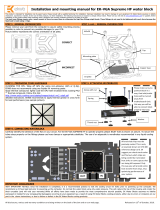
STEP 2: THE DESIGN OF YOUR WATER BLOCK
Please remove your motherboard from the computer to assure safest mounting
process in order to prevent any possible damages to your CPU and/or motherboard’s
circuit board (PCB). Sample picture bellow represents the correct orientation of block
and its flow path.
STEP 2.1 (optional): INSTALLING AMD MOUNTING PLATE
1) Place water block on an even surface and remove the four M3x12 DIN7991 screws attaching the top to the copper base using the enclosed 2mm allen key.
2) Place the AMD mounting plate on it.
3) Insert smaller gasket (28.3x1.78mm) into the milled groove and install larger gasket (54x2mm) into the gap between the mounting plate and copper top
4) Carefully rotate the top/mounting plate assembly with both hands and align it on top of the copper base with installed jet plate. Make sure gaskets stay in place!
5) Repeat step #3 and #4 if necassery. Using both hands press the waterblock assembly firmly together, rotate it and place it on it's back.
6) Screw in all four (4) M3x12 DIN7991 screws using the enclosed 2mm allen key.
STEP 3: INSTALLING BACKPLATE AND EASY MOUNT ASSEMBLY
STEP 3a: Intel LGA-775 and AMD socket motherboard:
1) Place motherboard on an even surface with front side facing down.
2) Install metal backplate together with EPDM rubber washer to the back of the
motherboard PCB and insert two (2) or four (4) M4x14 screw through all openings,
depending on the type of your motherboard
(see figure 1 and 2)
3) Carefully rotate motherboard assembly with one hand while holding the screws
and backplate with the other.
4) Install the rest of mounting system as shown
(see STEP 4)
STEP 3b: Intel LGA-1155/1156 socket motherboard:
1) Place motherboard on an even surface with front side facing down.
2) Install metal backplate together with 2mm plastic standoffs to the back
of the motherboard PCB and insert four (4) M4x14 screw through all four (4)
openings. Align the metal backplate to fit three LGA-115x ILM BP screws as the
metal backplate must sit on the LGA-115x ILM backplate
(see figure 1 and 2)
3) Carefully rotate motherboard assembly with one hand while holding the
screws and backplate with the other.
4) Install the rest of mounting system as shown
(see STEP 4)
CORRECT
INCORRECT
Gasket 54x2 mm
Gasket 28.3x1.78
EPDM rubber
M4x14 screw
Metal backplate
Motherboard
PCB
figure 1
figure 2: Isometric view of backplate assembly using EPM rubber washer – valid for
Intel LGA-775- and AMD socket motherboard. Picture is for reference only!
figure 1
figure 2: Isometric view of backplate assembly for LGA-1155 & -1156
Step #2 and #3:
Step #4:
Step #5 and #6:
Metal backplate
Motherboard
PCB
M4x14 screw
2mm standoff
M3x12
Copper base
Jet plate
Copper Top
Intel LGA socket
mounting plate

All disclosures, notices and warranty conditions are being written on the back of the box. Released on 25
th
of July, 2011.
STEP 3: INSTALLING BACKPLATE AND EASY MOUNT ASSEMBLY
STEP 4: INSTALLING THE MOUNTING SYSTEM
STEP 3c: Intel LGA-1366 socket motherboard:
1) Place motherboard on an even surface with front facing down.
2) Install metal backplate together with 2.5mm plastic standoffs to the back of the
motherboard PCB and insert four (4) M4x14 screw through all four (4) openings.
Metal backplate must sit on the LGA-1366 ILM backplate
(see figure 1 &2)
3) Carefully rotate motherboard assembly with one hand while holding the screws
and backplate with the other.
4) Install the rest of mounting system as shown
(see STEP 4)
Install the remaining components of the mounting system onto your
motherboard. It is mandatory to put 0.7mm plastic washer underneath each of
the M4 threaded stubs. Once the stubs are installed tighen them with the
philips head screwdriver.
STEP 5: PREPARING YOUR CPU; APPLYING THE THERMAL GREASE
STEP 6: INSTALLING THE WATER BLOCK
Cleaning the CPU: Once mounting mechanism is attached install the CPU into
the socket. Wipe the CPU’s contact surface (by using non–abrasive cloth or
Q-tip
,
as shown on sample photo).
Applying thermal compound: EK recommends blob or line method of applying
the enclosed Arctic Cooling MX-4™ thermal compound to the CPU heatspreader
(IHS) - see sample photo on right. The quantity of about two rice grains is just
about right. There is no need to cover the whole HIS. Applying too much thermal
grease will have negative impact on the cooling performance!
Install the waterblock on your CPU.
Place an enclosed compression
spring and thumb nut over each
threaded stub. Start fastening two
thumb nuts at a time, preferably in
cross pattern and do not tighten
them fully until all of them are
partially screwed in. Then - using
your fingers only - screw in all four
thumb nuts until you reach the end
of the thread.
STEP 10: CONNECTING WATER BLOCK TO THE COOLING CIRCUIT
IMPORTANT DISCLOSURES:
Carefully identify the direction of the flow in your circuit. For the EK-Supreme HF
series water block to operate properly the G1/4 port nearest to the center of the
water block MUST BE USED AS THE INLET PORT. EK recommends the use of
EK-PSC fittings. When using fittings other than EK-PSC series please use hose
clamps or appropriate substitute to secure the tubing to the barb. The use of
biocide containing and corrosion inhibiting coolant is always recommended for any
liquid cooling system.
VERY IMPORTANT NOTICE: Once the installation is completed, it is a recommended practice to test the
cooling circuit for leaks prior to powering up the computer. We recommend a 24 hour leak test prior to
powering up the computer. Do not test the water block using tap water pressure. This will rupture the top of
the housing and render the block unusable (and will void your warranty).While all efforts have been made to
provide the most comprehensive tutorial possible, EK Water Blocks assumes no liability expressed or implied
for any consequential damage(s) occurring to your equipment as a result of using EK Water Blocks cooling
products, either due to errors or omissions on our part in the above instructions, or due to failure or defect
in the EK Water Blocks cooling products.
WARRANTY:Our products are warranted against defects in materials or workmanship for a period of 24
months beginning from the date of delivery to the final user. During this period, products will be repaired or
have parts replaced at our discretion provided that: (I) the product is returned to the agent from whom it
was purchased; (II) the product has been purchased by an end user and has not used for commercial
purposes; (III) the product has not been misused, handled carelessly, or used in a manner other than in
accordance with the instructions provided describing its installation and proper use. This warranty does not
confer rights other than those expressly set out above and does not cover any claims for consequential loss
or damage. This warranty is offered as an extra benefit and does not affect your statutory rights as a
consumer. This warranty is voided if the product comes in contact with aggressive UV additives or other
improper liquids.
EK blocks are sealed with warranty void circular label, which proves that the block has withstood a pressure
leak test. Removing it will void only leaking issues. Any other RMA issues can be reported to
support@ekwaterblocks.com for further analysis.
REQUIRED TOOLS
philips screwdriver allen key 2mm
0.7mm plastic
washer
M4x14 screw
2.5mm standoff
figure 1
figure 2: Isometric view of backplate assembly for LGA-1366
Metal backplate
Motherboard
PCB
M4x14 screw
M4 double side
threaded stub
M4 threaded
thumb nut
Compression spring
INLET
OUTLET
/