Page is loading ...

Page 1
This appliance may be installed in
an aftermarket, permanently located,
manufactured home (USA only) or mobile
home, where not prohibited by state or
local codes.
This appliance is only for use with the type
of gas indicated on the rating plate. This
appliance is not convertible for use with
other gases, unless a certied kit is used.
NOTE: Barrier required, but may be sold separately.
HOT GLASS
DO NOT TOUCH
NEVER
WILL
CAUSE BURNS.
GLASS
UNTIL COOLED.
ALLOW CHILDREN
TO TOUCH GLASS.
WARNING
A barrier designed to reduce the risk of burns from the
hot viewing glass is provided with this appliance and shall
be installed for the protection of children and other at-risk
individuals.
INSTALLATION INSTRUCTIONS
AND OWNER’S MANUAL
WARNING
FIRE OR EXPLOSION HAZARD
If the information in this manual is not
followed exactly, a re or explosion may
result causing property damage, personal
injury or loss of life.
— Do not store or use gasoline or other
ammable vapors and liquids in the
vicinity of this or any other appliance.
— WHAT TO DO IF YOU SMELL GAS
• Do not try to light any appliance.
• Do not touch any electrical switch; do
not use any phone in your building.
• Leave the building immediately.
• Immediately call your gas supplier
from a neighbor’s phone. Follow the
gas supplier’s instructions.
• If you cannot reach your gas supplier,
call the re department.
— Installation and service must be
performed by a qualied installer,
service agency or the gas supplier.
INSTALLER:
Leave this manual with the appliance.
CONSUMER:
Retain this manual for future reference.
DIRECT VENT
ZERO CLEARANCE GAS
FIREPLACE HEATER SERIES:
MILLIVOLT (MV)
DVCD(32,36,42)FP30(N,P)-1
DIRECT IGNITION (DI)
DVCD(32,36,42)FP50N-1
INTERMITTENT PILOT (IP)
DVCD(32,36,42)FP7(0,1)(N,P)-1
UL FILE NO. MH30033
GAS-FIRED
WARNING
If not installed, operated and maintained
in accordance with the manufacturer’s
instructions, this product could expose you
to substances in fuel or from fuel combustion
which can cause death or serious illness.
CARTON CONTENTS
Accessory Sheet Rockwool
Hardware Pack Registration Card
AA Battery (4) (IP only) Power Adaptor (IP only)
Junction Box Cover Receptical
Logs Decorative Rocks

31509-13-0416Page 2
TABLE OF CONTENTS
IMPORTANT SAFETY INFORMATION ........................................................................................................................ 3
SAFETY INFORMATION FOR USERS OF LP GAS.................................................................................................... 4
REQUIREMENTS FOR MASSACHUSETTS ............................................................................................................... 5
INTRODUCTION .......................................................................................................................................................... 6
SPECIFICATIONS ........................................................................................................................................................ 7
VENT SYSTEM IDENTIFICATION ............................................................................................................................... 8
SPECIAL VENT SYSTEMS ......................................................................................................................................... 8
FIREPLACE DIMENSIONS ......................................................................................................................................... 9
CLEARANCES ........................................................................................................................................................... 10
LOCATING FIREPLACE .............................................................................................................................................11
GAS SUPPLY ............................................................................................................................................................. 12
INSTALLATION ..................................................................................................................................................... 13-17
VENTING FIREPLACE - TOP ............................................................................................................................... 18-20
EXAMPLES - TOP VENT RUN .................................................................................................................................. 21
VENTING FIREPLACE - REAR ................................................................................................................................. 22
EXAMPLES - REAR VENT RUN ............................................................................................................................... 23
REAR VENT CONVERSION ...................................................................................................................................... 24
VENT CLEARANCES ................................................................................................................................................ 25
FRAMING AND FINISHING .................................................................................................................................. 26-27
TERMINATION CLEARANCES ................................................................................................................................. 28
HORIZONTAL TERMINATION ................................................................................................................................... 29
VERTICAL TERMINATION ................................................................................................................................... 30-31
DVVK-4F FLEX VENT INSTRUCTIONS .................................................................................................................... 32
DVVK-4RE VENT KIT INSTALLATION INSTRUCTIONS ..................................................................................... 33-35
DVCD32 LOG IDENTIFICATION ............................................................................................................................... 36
LOG PLACEMENT - 32” FIREPLACES ................................................................................................................ 37-45
DVCD36 LOG IDENTIFICATION ............................................................................................................................... 46
LOG PLACEMENT - 36” FIREPLACES ................................................................................................................ 47-54
DVCD42 LOG IDENTIFICATION ............................................................................................................................... 55
LOG PLACEMENT - 42” FIREPLACES ................................................................................................................ 56-64
MILLIVOLT OPERATING INSTRUCTIONS (FP3 SERIES) .................................................................................. 65-66
MILLIVOLT STANDING PILOT WIRING DIAGRAM (FP3 SERIES) .......................................................................... 67
MILLIVOLT STANDING PILOT LIGHTING INSTRUCTIONS (FP3 SERIES) ............................................................ 68
MILLIVOLT STANDING PILOT TROUBLESHOOTING (FP3 SERIES) ..................................................................... 69
DIRECT IGNITION LIGHTING INSTRUCTIONS (FP5 SERIES) ............................................................................... 70
DIRECT IGNITION WIRING DIAGRAM (FP5 SERIES) ............................................................................................. 71
OPTIONAL REMOTE CONTROL .............................................................................................................................. 72
INITIAL START UP GAS LINE PURGE (FP5 SERIES) ............................................................................................. 72
DIRECT IGNITION TROUBLESHOOTING ................................................................................................................ 72
DIRECT IGNITION PROPANE/LP GAS CONVERSION (FP5 SERIES) ................................................................... 73
PROPANE/LP GAS CONVERSION (FP5 SERIES) ................................................................................................... 74
IPI ELECTRONIC SYSTEM OPERATING INSTRUCTIONS (FP7 SERIES) ............................................................. 75
IPI ELECTRONIC SYSTEM WIRING DIAGRAM (FP7 SERIES)............................................................................... 76
INTERMITTENT PILOT LIGHTING INSTRUCTIONS (FP7 SERIES) ....................................................................... 77
INTERMITTENT PILOT CONTROL SYSTEM TROUBLESHOOTING (FP7 SERIES) ......................................... 78-80
MAINTENANCE AND SERVICE ................................................................................................................................ 81
DVCD32FP(3,5,7) PARTS LIST ................................................................................................................................. 82
DVCD32FP(3,5,7) PARTS VIEW ............................................................................................................................... 83
DVCD36FP(3,5,7) PARTS LIST ................................................................................................................................. 84
DVCD36FP(3,5,7) PARTS VIEW ............................................................................................................................... 85
DVCD42FP(3,5,7) PARTS LIST ................................................................................................................................. 86
DVCD42FP(3,5,7) PARTS VIEW ............................................................................................................................... 87
FBB4 OPTIONAL VARIABLE SPEED BLOWER INSTALLATION ........................................................................ 88-89
MASTER PARTS DISTRIBUTOR LIST ...................................................................................................................... 90
HOW TO ORDER REPAIR PARTS ............................................................................................................................ 90
JUNCTION BOX WIRING INSTALLATION INSTRUCTIONS .................................................................................... 91
OPTIONAL BRICK LINER INSTALLATION INSTRUCTIONS .................................................................................... 92
ACCESSORIES ......................................................................................................................................................... 92
DECORATIVE ACCESORIES .................................................................................................................................... 93
WARRANTY ............................................................................................................................................................... 94
APPLIANCE SERVICE HISTORY .............................................................................................................................. 95
SECTION PAGE

31509-13-0416 Page 3
DO NOT OPERATE THIS APPLIANCE WITHOUT GLASS FRONT PANEL INSTALLED
Before enclosing the vent pipe assembly, operate the appliance to ensure it is venting properly.
• Due to high temperatures the appliance should be
located out of trafc and away from furniture and
draperies.
• The glass front or any part removed for servicing
the appliance must be replaced prior to operating
the appliance. Work should be done by a qualied
service person.
• Keep burner and control compartment clean.
• Vent cap is hot while replace is in operation.
• Installation and repair should be done by a
QUALIFIED SERVICE PERSON. The appliance
should be inspected before use and at least annually
by a qualified service person. More frequent
cleaning may be required due to excessive lint from
carpeting, bedding materials, etc. It is imperative
that control compartments, burners and circulating
air passageways of the appliance be kept clean.
• DO NOT put anything around the replace that will
obstruct the ow of ventilation air.
• Clearance in accordance with local installation
codes and the requirements of the gas supplier.
• DO keep the appliance area clear and free from
combustible material, gasoline and other ammable
vapors and liquids.
• DO examine venting system periodically and replace
damaged parts.
• DO make a periodic visual check of pilot and burners.
Clean and replace damaged parts.
• CAUTION: The glass used in your replace is
tempered glass. If the glass is cracked or damaged in
any way, it should be replaced only with a complete
glass frame assembly from Empire. See parts list
on Pages 56 - 61 for ordering.
• DO NOT use this replace if any part has been under
water. Immediately call a qualied service technician
to inspect the heater and to replace any part of the
control system and any gas control which has been
under water.
• Any safety screen or guard removed for servicing
an appliance must be replaced prior to operating
the appliance.
• If this appliance is installed directly on carpeting,
tile or other combustible material other than wood
ooring the appliance shall be installed on a metal
or wood panel extending the full width and depth
of the appliance.
The base referred to above does not mean the
fireproof base as used on wood stoves. The
protection is for rugs that are extremely thick and
light colored tile.
• Children and adults should be alerted to the hazards
of high surface temperatures and should stay away
to avoid burns or clothing ignition.
• Young children should be carefully supervised when
they are in the same room as the appliance.
• Clothing or other ammable material should not be
placed on or near the appliance.
• Adequate accessibility clearances for servicing and
proper operation.
• This appliance must not share or be connected to a
ue serving a separate solid-fuel burning appliance.
• Keep the area around your appliance clear of
combustible materials, gasoline and other ammable
vapor and liquids.
• Under no circumstances should any solid fuels
(wood, coal, paper or cardboard etc.) be used in
this appliance.
• The ow of combustion and ventilation air must not
be obstructed in any way.
• Young children should be carefully supervised
when they are in the same room as the appliance.
Toddlers, young children, and others may be sus-
ceptible to accidental contact burns. A physical
barrier is recommended if there are at-risk individ-
uals in the house. To restrict access to a replace
or stove, install an adjustable safety gate to keep
toddlers young children, and other at-risk individ-
uals out of the room and away from hot surfaces.
• A barrier designed to reduce the risk of burns from
the hot viewing glass is provided with this appli-
ance and shall be installed for the protection of
children and other at-risk individuals. Barrier re-
quired, but may be sold separately.
• If the barrier becomes damaged, the barrier shall
be replaced with the manufacturer’s barrier for
this appliance.
• Any safety screen, guard, or barrier removed for
servicing an appliance must be replaced prior to
operating the appliance.
IMPORTANT SAFETY INFORMATION

31509-13-0416Page 4
SAFETY INFORMATION FOR USERS OF LP GAS
Propane (LP-Gas) is a ammable gas which can cause
res and explosions. In its natural state, propane is
odorless and colorless. You may not know all the fol-
lowing safety precautions which can protect both you
and your family from an accident. Read them carefully
now, then review them point by point with the mem-
bers of your household. Someday when there may not
be a minute to lose, everyone’s safety will depend on
knowing exactly what to do. If, after reading the follow-
ing information, you feel you still need more informa-
tion, please contact your gas supplier.
LP-GAS WARNING ODOR
If a gas leak happens, you should be able to smell the
gas because of the odorant put in the LP-Gas. That’s
your signal to go into immediate action!
• Donotoperateelectricswitches,lightmatches,use
yourphone.Donotdoanythingthatcouldignitethe
gas.
• Geteveryoneoutofthebuilding,vehicle,trailer,or
area.DothatIMMEDIATELY.
• Closeallgastankorcylindersupplyvalves.
• LP-Gasisheavierthanairandmaysettleinlowareas
suchasbasements.Whenyouhavereasontosuspect
agasleak,keepoutofbasementsandotherlowar-
eas.Stayoutuntilreghtersdeclarethemtobesafe.
• Useyourneighbor’sphoneandcallatrainedLP-Gas
servicepersonandtheredepartment.Eventhough
youmaynotcontinuetosmellgas,donotturnonthe
gasagain.Donotre-enterthebuilding,vehicle,trailer,
or area.
• Finally,lettheservicemanandreghterscheckfor
escapedgas.Havethemairouttheareabeforeyou
return.ProperlytrainedLP-Gasservicepeopleshould
repairtheleak,thencheckandrelightthegasappli-
anceforyou.
NO ODOR DETECTED - ODOR FADE
Some people cannot smell well. Some people cannot
smell the odor of the chemical put into the gas. You
must nd out if you can smell the odorant in propane.
Smokingcandecreaseyourabilitytosmell.Beingaround
anodorforatimecanaffectyoursensitivityorabilityto
detectthatodor.Sometimesotherodorsintheareamask
thegasodor.Peoplemaynotsmellthegasodorortheir
mindsareonsomethingelse.Thinkingaboutsmellinga
gasodorcanmakeiteasiertosmell.
The odorant in LP-Gas is colorless, and it can fade
under some circumstances.Forexample,ifthereisan
undergroundleak,themovementofthegasthroughsoil
canltertheodorant.OdorantsinLP-Gasalsoaresubject
tooxidation.Thisfadingcanoccurifthereisrustinsidethe
storagetankorinirongaspipes.
Theodorantinescapedgascanadsorborabsorbonto
orintowalls,masonryandothermaterialsandfabricsin
aroom.Thatwilltakesomeoftheodorantoutofthegas,
reducingitsodorintensity.
LP-Gasmaystratifyinaclosedarea,andtheodorintensi-
tycouldvaryatdifferentlevels.Sinceitisheavierthanair,
theremaybemoreodoratlowerlevels.Alwaysbesensi-
tivetotheslightestgasodor.Ifyoudetectanyodor,treatit
asaseriousleak.Immediatelygointoactionasinstructed
earlier.
SOME POINTS TO REMEMBER
• Learn to recognize the odor of LP-Gas.Yourlocal
LP-GasDealercangiveyoua“ScratchandSniff”
pamphlet.Useittondoutwhatthepropaneodor
smellslike.IfyoususpectthatyourLP-Gashasa
weakorabnormalodor,callyourLP-GasDealer.
• Ifyouarenotqualied,donotlightpilotlights,perform
service,ormakeadjustmentstoappliancesonthe
LP-Gassystem.Ifyouarequalied,consciouslythink
abouttheodorofLP-Gaspriortoandwhilelightingpi-
lotlightsorperformingserviceormakingadjustments.
• Sometimesabasementoraclosed-uphousehasa
mustysmellthatcancoveruptheLP-Gasodor.Donot
trytolightpilotlights,performservice,ormakeadjust-
mentsinanareawheretheconditionsaresuchthat
youmaynotdetecttheodoriftherehasbeenaleakof
LP-Gas.
• Odorfade,duetooxidationbyrustoradsorptionon
wallsofnewcylindersandtanks,ispossible.There-
fore,peopleshouldbeparticularlyalertandcareful
whennewtanksorcylindersareplacedinservice.
Odorfadecanoccurinnewtanks,orreinstalledold
tanks,iftheyarelledandallowedtosettoolongbe-
forerelling.Cylindersandtankswhichhavebeenout
ofserviceforatimemaydevelopinternalrustwhich
willcauseodorfade.Ifsuchconditionsaresuspected
toexist,aperiodicsnifftestofthegasisadvisable.
If you have any question about the gas odor, call
your LP-Gas dealer. A periodic sniff test of the LP-
Gas is a good safety measure under any condition.
• If,atanytime,youdonotsmelltheLP-Gasodorant
andyouthinkyoushould,assumeyouhavealeak.
Thentakethesameimmediateactionrecommended
abovefortheoccasionwhenyoudodetecttheodor-
ized LP-Gas.
• Ifyouexperienceacomplete“gasout,”(thecontainer
isundernovaporpressure),turnthetankvalveoff
immediately.Ifthecontainervalveislefton,thecon-
tainermaydrawinsomeairthroughopeningssuch
aspilotlightorices.Ifthisoccurs,somenewinternal
rustingcouldoccur.Ifthevalveisleftopen,thentreat
thecontainerasanewtank.Alwaysbesureyourcon-
tainerisundervaporpressurebyturningitoffatthe
containerbeforeitgoescompletelyemptyorhavingit
relledbeforeitiscompletelyempty.

31509-13-0416 Page 5
REQUIREMENTS FOR MASSACHUSETTS
Forallsidewallhorizontallyventedgasfueledequipment
installedineverydwelling,buildingorstructureusedin
wholeorinpartforresidentialpurposes,includingthose
ownedoroperatedbytheCommonwealthandwherethe
sidewallexhaustventterminationislessthansevenfeet
abovenishedgradeintheareaoftheventing,including
butnotlimitedtodecksandporches,thefollowing
requirementsshallbesatised:
1. INSTALLATION OF CARBON MONOXIDE
DETECTORS.Atthetimeofinstallationoftheside
wallhorizontalventedgasfueledequipment,the
installingplumberorgasttershallobservethatahard
wiredcarbonmonoxidedetectorwithanalarmand
batteryback-upisinstalledontheoorlevelwhere
thegasequipmentistobeinstalled.Inaddition,
theinstallingplumberorgasttershallobservethat
abatteryoperatedorhardwiredcarbonmonoxide
detectorwithanalarmisinstalledoneachadditional
levelofthedwelling,buildingorstructureservedby
thesidewallhorizontalventedgasfueledequipment.
Itshallbetheresponsibilityofthepropertyownerto
securetheservicesofqualiedlicensedprofessionals
fortheinstallationofhardwiredcarbonmonoxide
detectors
a. Intheeventthatthesidewallhorizontallyvented
gasfueledequipmentisinstalledinacrawlspace
oranattic,thehardwiredcarbonmonoxide
detectorwithalarmandbatteryback-upmaybe
installedonthenextadjacentoorlevel.
b. Intheeventthattherequirementsofthis
subdivisioncannotbemetatthetimeof
completionofinstallation,theownershallhave
aperiodofthirtydaystocomplywiththeabove
requirements;provided,however,thatduring
saidthirtydayperiod,abatteryoperatedcarbon
monoxidedetectorwithanalarmshallbeinstalled.
2. APPROVED CARBON MONOXIDE DETECTORS.
Eachcarbonmonoxidedetectorasrequiredin
accordancewiththeaboveprovisionsshallcomply
withNFPA720andbeANSI/UL2034listedandIAS
certied.
3. SIGNAGE.Ametalorplasticidenticationplate
shallbepermanentlymountedtotheexteriorofthe
buildingataminimumheightofeightfeetabove
gradedirectlyinlinewiththeexhaustventterminalfor
thehorizontallyventedgasfueledheatingappliance
orequipment.Thesignshallread,inprintsizeno
lessthan1/2inchinsize,“GAS VENT DIRECTLY
BELOW. KEEP CLEAR OF ALL OBSTRUCTIONS”.
4. INSPECTION.Thestateorlocalgasinspectorofthe
sidewallhorizontallyventedgasfueledequipment
shallnotapprovetheinstallationunless,upon
inspection,theinspectorobservescarbonmonoxide
detectorsandsignageinstalledinaccordancewiththe
provisionsof248CMR5.08(2)(a)1through4.
(b) EXEMPTIONS:Thefollowingequipmentisexempt
from248CMR5.08(2)(a)1through4:
1. TheequipmentlistedinChapter10entitled
“EquipmentNotRequiredToBeVented”inthe
mostcurrenteditionofNFPA54asadoptedby
theBoard;and
2. ProductApprovedsidewallhorizontallyvented
gasfueledequipmentinstalledinaroomor
structureseparatefromthedwelling,building
orstructureusedinwholeorinpartfor
residentialpurposes.
(d) MANUFACTURER REQUIREMENTS - GAS
EQUIPMENT VENTING SYSTEM NOT
PROVIDED.WhenthemanufacturerofaProduct
Approvedsidewallhorizontallyventedgasfueled
equipmentdoesnotprovidethepartsforventing
theuegases,butidenties“specialventing
systems”,thefollowingrequirementsshallbe
satisedbythemanufacturer:
1. Thereferenced“specialventingsystem”
instructionsshallbeincludedwiththe
applianceorequipmentinstallation
instructions;and
2. The“specialventingsystems”shallbeProduct
ApprovedbytheBoard,andtheinstructions
forthatsystemshallincludeapartslistand
detailedinstallationinstruction.
(e) AcopyofallinstallationinstructionsforallProduct
Approvedsidewallhorizontallyventedgasfueled
equipment,allventinginstructions,allpartslists
forventinginstructions,and/orallventingdesign
instructionsshallremainwiththeapplianceor
equipmentatthecompletionoftheinstallation.

31509-13-0416Page 6
Instructions to Installer
1. Installermustleaveinstructionmanualwithowner
afterinstallation.
2. Installermusthaveownerlloutandmailwarranty
cardsuppliedwiththereplace.
3. Installershouldshowownerhowtostartandoperate
thereplace.
Thisdirectventgasreplaceheaterisdesignedtooperate
withallcombustionairbeingsiphonedfromtheoutsideof
thebuildingandallexhaustgasesexpelledtotheoutside
ofthebuilding.Theinformationcontainedinthismanual
pertainstoallmodelsandgascontrolsystemsunless
otherwisenoted.
Appliance Certication
WARNING: This unit is not for use with solid fuels.
Thisreplaceisdesigncertiedinaccordancewith
AmericanNationalStandard/CSAStandardANSIZ21.88/
CSA2.33andbyUnderwritersLaboratoriesasaDirect
VentGasFireplaceHeaterandshallbeinstalledaccording
totheseinstructions.
Consultyourlocalbuildingcodeagency,priorto
installation,toensurecompliancewithlocalcodes-
includingpermitsandinspections.
Thereplace,wheninstalled,mustbeelectrically
groundedinaccordancewithlocalcodesor,inabsenceof
localcodes,withtheNational Electric Code ANSI/NFPA
70orCanadianElectriccode,CSAC22.1,ifanexternal
electricalsourceisutilized.
Thesemodelsmaybeinstalledinabedroomorbed-sitting
roomintheU.S.A.andCanada.
Qualied Installing Agency
Installationandreplacementofgaspiping,gasutilization
equipmentoraccessoriesandrepairandservicingof
equipmentshallbeperformedonlybyaqualiedagency.
Theterm“qualiedagency”meansanyindividual,
rm,corporationorcompanywhicheitherinpersonor
througharepresentativeisengagedinandisresponsible
for(a)theinstallationorreplacementofgaspipingor
(b)theconnection,installation,repairorservicingof
equipment,whoisexperiencedinsuchwork,familiarwith
allprecautionsrequiredandhascompliedwithallthe
requirementsoftheauthorityhavingjurisdiction.
Commonwealth of Massachusetts: Theinstallation
mustbemadebyalicensedplumberorgastterinthe
CommonwealthofMassachusetts.
WARNING:ANYCHANGETOTHISFIREPLACEOR
ITS CONTROLS CAN BE DANGEROUS.
Improperinstallationoruseofthereplacecancause
seriousinjuryordeathfromre,burns,explosions,or
carbonmonoxidepoisoning.
Theinstallationmustconformwithlocalcodesor,in
theabsenceoflocalcodes,withtheNational Fuel Gas
Code ANSI Z223.1/NFPA 54* Natural Gas and Propane
Installation Code, or CSA B149.1 in Canada. *Available from
the American National Standards Institute, Inc. 11 West 42nd St., New
York, N.Y. 10036.
Any alteration of the original design, installed other
than as shown in these instructions or use with
a type of gas not shown on the rating plate is the
responsibility of the person and company making the
change.
Important
AllcorrespondenceshouldrefertocompleteModel
Number,SerialNumberandtypeofgas.
High Altitude
Wheninstallingthisunitatanelevationabove2000feet
(intheUnitedStates)itmaybenecessarytodecrease
theinputratingbychangingtheexistingburneroricetoa
smallersize.Generally,inputshouldbereduced4percent
foreach1000feetabovesealevel.However,iftheheating
valueofthegashasbeenreduced,thisgeneralrulemay
notapply.Checkwithlocalgasutilityforproperoricesize
identication.
Canadian High Altitude
Altitude:0-4500feet(0-1370m)
Wheninstallingthisunitatanelevationabove4500feet
(inCanada),checkwithlocalauthorities.
Consultyourlocalgasutilityforassistanceindetermining
theproperoriceforlocation.
Preparation
Thisdirectventgasreplaceanditscomponentsare
testedandsafewheninstalledinaccordancewiththis
InstallationManual.Reporttoyourdealeranyparts
damagedinshipment,specicallycheckglasscondition.
Donotinstallunitwithdamaged,incomplete,orsubstitute
parts.Readallinstructionsbeforestartinginstallationand
followtheseinstructionscarefullyduringinstallationto
insuremaximumbenetandsafety.Failuretofollowthem
willvoidyourwarrantyandmaypresentarehazard.
Thewarrantywillbevoidedby,andthewarranter
disclaimsanyresponsibilityforthefollowingactions:
• Installationofanydamagedreplaceorventsystem
component.
• Modicationofthereplaceordirectventsystem.
• InstallationotherthanasinstructedbyEmpireComfort
Systems,Inc.
• Improperpositioningofthelogs,glassdooror
decorativerock.
• Installationand/oruseofanycomponentpartnot
manufacturedorapprovedbymanufacturer.
INTRODUCTION

31509-13-0416 Page 7
SPECIFICATIONS
DVCD32NAT DVCD32LP DVCD36NAT DVCD36LP DVCD42NAT DVCD42LP
InputBTU/HrMaximum 18,000 18,000 20,000 20,000 25,000 25,000
BTU/HrMinimum(millivoltonly) 14,000 14,000 14,000 16,500 18,000 19,500
KWH (Maximum) 5.3 5.9 7.3
(Minimum) 4.1 4.1 5.3
NAT.
Orice
#46 (.081”)
P254
- 2.10 mm P288 -
#42 (.0935”)
P286
-
AirShutterOpening
1/16”
(1.6mm)
- 1/16” (1.6mm) - 3/16”(4.8mm) -
LP
Orice -
#56 (.0465”)
P287
-
#55 (.052”)
P182
-
1.45 mm
P208
AirShutterOpening -
1/4”
(6.3mm)
-
5/16”
(7.9mm)
-
5/16”
(7.9mm)
Heightwithoutstandoff -
32 3/4”
(832mm)
-
32 3/4”
(832mm)
-
34 3/4”
(883mm)
Width -
34”
(864mm)
-
37”
(940mm)
-
43”
(1092mm)
Depth -
16 3/8”
(416mm)
-
16 3/8”
(416mm)
-
16 3/8”
(416mm)
GasInletShutoffValve(Pipe) - 1/2 NPT - 1/2 NPT - 1/2 NPT
NOTE: Airshuttersettings are factory minimum settings. Some venting congurations may require minor air shutter adjustments for
optimumperformance.
Remote Control Options
& Accessories
Description Models Used On
FRBC MillivoltBatteryRemoteON/OFF DVCD(32,36,42)FP(3,7)
FRBTC MillivoltBatteryRemoteThermostat DVCD(32,36,42)FP(3,7)
FREC DirectIgnition/Millivolt120VON/OFFRemote DVCD(32,36,42)FP(3,5)
TMW MillivoltWirelessWallThermostat DVCD(32,36,42)FP(3,7)
TRW MillivoltReedSwitchWallThermostat DVCD(32,36,42)FP(3,7)
FWS-1 DirectIgnition/MillivoltWallSwitch DVCD(32,36,42)FP(3,5,7)
Venting Options Description
DVVK-4TSP Topventkit(horizontal)-4½"to6"(114.3mmto152mm)wallthickness
DVVK-4TP Topventkit(horizontal)-8"to12"(203mmto305mm)wallthickness
DVVK-4RP Rearventkit(horizontal)-5"to7"(127mmto178mm)wallthickness
DVVK-4VP Verticalventkit
DVVK-4F Horizontalexventkit(4'FLEX)
DVVK-4RE Horizontalroundtermination(wallthicknessupto117/16")
DV822 VinylsidingkitforDVVK-4RE
FIREPLACE BARRIER SCREENS
SCREEN MODEL DESCRIPTION FIREPLACE MODELS USED ON
DVFB32SBL FireplaceBarrierScreen,MatteBlack DVCD32FP
DVFB36SBL FireplaceBarrierScreen,MatteBlack DVCD36FP
DVFB42TBL FireplaceBarrierScreen,MatteBlack DVCD42FP
Note:Arescreenisrequiredforoperationoftheappliance,butaresoldseparately.Followtheinstructionsthatcomewithyourrescreen
forproperinstallation.

31509-13-0416Page 8
Figure 1
Special Venting Components (Simpson Duravent)
SeeEmpireComfortSystemsRetailPriceListforSimpsonDuraventpartnumbersandpricing.
SpecialDVVentKits
AvailablefromEmpireComfortSystems,Inc.dealers
DVVK-4FV VerticalFlexVentKit4"x7"
DVVK-4VP
Direct-VentFireplaceVentKit-Vertical,IncludesSD-991,SD-953,and
SD-943
DVVK-4TP
Direct-VentFireplaceVentKitforTopVent,Thru-the-wall,8to11inchwall
thickness,IncludesSD-911,SD-985,SD-990andSD-942
DVVK-4RP
Direct-VentFireplaceVentKitforRearVent,5to7inchwallthickness,
(standardthru-the-wallventing)IncludesSD-908,SD-985andSD-942
DVVK-4RE
Direct-VentFireplaceVentKitforRearVent,Thru-thewall,5to7inchwall
thickness,(standardthru-the-wallventing)IncludesSD-908,SD985and
SD-942
DVVK-4TSP
Direct-VentFireplaceVentKitforTopVent,Thru-the-wall,5to7inchwall
thickness,IncludesSD-908,SD-985,SD-990andSD-942
VIB6A VerticalInletBafeKitfor65/8"diameter.
VIB7A VerticalInletBafeKitfor7"diameter.
VENT SYSTEM IDENTIFICATION
ThefollowingventsystemsareacceptableforusewiththeDVCD
(32,36,42)seriesreplaces:
SimpsonDuravent®GS4"-6⅝"
AmericanMetalProducts4"-6⅝"
SelkirkDirect-Temp®4"-6⅝"
SecuritySecureVent®4"-6⅝"
ExcelDV4”-6⅝”
MetalFabSureSeal®4”-6⅝”
BDMManufacturing4”-6⅝”
EmpireHorizontalRoundTerminationKits:
DVVK-4RE, DVVK-4REVS
EmpireFlexventKits:DVVK-4F,DVVK-4FREVS,DVVK-4FRE
SPECIAL VENT SYSTEMS
Begintheventsysteminstallationbyselectingthetypeofventing
tobeinstalledandthepaththatitwilltake.Verifythatclearances
aremetthroughoutthepathoftheventingsystem.Determineif
thereplaceistobeventedoutthetoporouttherear.
NOTICE:Somereplacescannotbeventedouttherearofthe
replace.
Determinehowtheventsystemwillbeterminatedoutthe
sideofthehouseorthroughtheroof.Verifyclearancesforthe
termination.
Whenselectingaventsystemforusewiththereplace,referto
the“SpecialVentSystems”sectioninthismanualtodetermine
whatsystemsareacceptable.Checkallclearancesandventing
components.Identifyifanyproblemsexistingintheventsystem.
Use Figure 22onpage18fortopventingorFigure 32onpage
22forrearventingtoeliminateissuesafterinstallation.Check
pipediameteronventsystemandreplacetoverifythesizeis
thesame.
NOTICE: All outer connection joints must be sealed with
aluminum tape, screws or silicone sealant rated above
300°F/149°C. The inner ue joints do not require any sealant.

31509-13-0416 Page 9
Figure 2
Dim DVCD32 DVCD36 DVCD42
A
34"
864 mm
37"
940 mm
43"
1092 mm
B
31"
787 mm
34"
864 mm
40"
1016 mm
C
231/16"
585 mm
231/16"
585 mm
251/16"
636 mm
D
355/8"
905 mm
355/8"
905 mm
375/8"
956 mm
E
323/4"
832 mm
323/4"
832 mm
343/4"
883 mm
F
163/8"
416 mm
163/8"
416 mm
16 3/8
416 mm
G
241/2"
622 mm
241/2"
622 mm
261/2"
673 mm
H
71/8"
181 mm
71/8"
181 mm
71/8"
181 mm
I
211/2"
546 mm
241/2"
622 mm
301/2"
774 mm
J
103/4"
273 mm
121/4"
311 mm
151/4"
387 mm
K
91/4"
235 mm
91/4"
235 mm
91/4"
235 mm
FIREPLACE DIMENSIONS

31509-13-0416Page 10
CLEARANCES
Clearance to Combustibles
Back 0"(0mm)
Side 0"(0mm)
Floor 0"(0mm)
TopStand-off 0"(0mm)
TopFramingEdge 3"(76mm)
Figure 3
Combustible Material
Nogreetingcards,stockingsorornamentationofanytypeshould
beplacedonorattachedtothereplace.Theowofheatcan
ignitecombustibles.
Note:WhenusingEmpireEMBF,UMC,andUMFSeries
FullMantelswithDVCD32andDVCD36SeriesFireplaces,
combustibleclearancemaybereducedto1”clearancefromtop
edgeofreplaceface.
Figure 4
Mantel Chart
Figure 5
Clearances
Clearancefromtopfrontedgeofreplacetoceilingis36”
Clearancefromsideofreplacetoadjacentsidewallis6”.
Figure 6

31509-13-0416 Page 11
Figure 7
Note:IslandandRoomDividerinstallationispossibleaslongasthehorizontalportionoftheventsystemdoesnotexceed20feetwith
aminimumverticalrunof8feet.SeedetailsinVentingSection.
WhenyouinstallyourDirectVentFireplaceinRoomdividerorFlatonwallcornerpositions,aminimumof6inchesclearancemustbe
maintainedfromtheperpendicularwallandthefrontedgeoftheappliance.
LOCATING FIREPLACE

31509-13-0416Page 12
GAS SUPPLY
Thegaspipelinecanbebroughtinthroughtherightorleftsideof
theappliance.ConsultthecurrentNationalFuelGasCode,ANSI
Z223.1CAN/CGA-B149(.1or.2)installationcode.
Recommended Gas Pipe Diameter
PipeLength
Schedule40Pipe
InsideDiameter
Tubing,TypeL
Outside Diameter
Nat. L.P. Nat. L.P.
0-10feet 1/2” 3/8” 1/2” 3/8”
10-40feet 1/2” 1/2” 5/8” 1/2”
40-100feet 1/2” 1/2” 3/4” 1/2”
100-150feet 3/4” 1/2” 7/8” 3/4”
Note:Neveruseplasticpipe.Checktoconrmwhetheryour
localcodesallowcoppertubingorgalvanized.
Note: Sincesomemunicipalitieshaveadditionallocalcodes,itis
alwaysbesttoconsultyourlocalauthorityandinstallationcode.
Theuseofthefollowinggasconnectorsisrecommended:
— ANSZ21.24ApplianceConnectorsofCorrugatedMetal
TubingandFittings.
— ANSZ21.45AssembledFlexibleApplianceConnectorsof
OtherThanAll-MetalConstruction
Theaboveconnectorsmaybeusedifacceptablebytheauthority
havingjurisdiction.ThestateofMassachusettsrequiresthata
exibleapplianceconnectorcannotexceedthreefeetinlength.
FLEXIBLE GAS LINE CONNECTION
GAS SUPPLY
TEE HANDLE
FLEX TUBING
FLARE FITTING FLARE SHUT
OFF VALVE
Figure 8
GasSupplyPressure(inchesw.c.)
Minimum Normal Maximum
Natural Gas 4.5" 7.0" 14.0"
LP(Propane) 10.8" 11.0" 14.0"
ManifoldPressure(inchesw.c.)
Normal (HI)
Natural Gas 3.5"
LP(Propane) 10.0"
Installing a New Main Gas Cock
Eachapplianceshouldhaveitsownmanualgascock.
Amanualmaingascockshouldbelocatedinthevicinityof
theunit.Wherenoneexists,orwhereitssizeorlocationisnot
adequate,contactyourlocalauthorizedinstallerforinstallationor
relocation.
Compoundsusedonthreadedjointsofgaspipingshallbe
resistanttotheactionofliqueedpetroleumgases.Thegas
linesmustbecheckedforleaksbytheinstaller.Thisshouldbe
donewithasoapsolutionwatchingforbubblesonallexposed
connections,andifunexposed,apressuretestshouldbemade.
Never use an exposed ame to check for leaks. Appliance
must be disconnected from piping at inlet of control valve
and pipe capped or plugged for pressure test. Never
pressure test with appliance connected; control valve will
sustain damage!
NOTE: Themillivoltgascontrolsareequippedwithacaptured
screwtypepressuretestpoint,thereforeitisnotnecessaryto
providea1/8”testpointupstreamofthecontrol.
Ondirectignitionvalves,hexplugsmaybereplacedwithhose
ttingsforpressurechecks,thenreinstalledbeforeoperating
replace.
Whenusingcopperorexconnectoruseonlyapprovedttings.
Theapplianceandit’sindividualshutoffvalvemustbe
disconnectedfromsupplypipingsystemduringanypressure
testingofthatsystemattestpressuresinexcessof1/2psig
(3.5kPa).
Theappliancemustbeisolatedfromthegassupplypiping
systembyclosingitsindividualmanualshutoffvalveduringany
pressuretestingofthegassupplypipingsystemattestpressures
equaltoorlessthan1/2psig(3.5kPa).
Attention! Ifoneoftheproceduresresultsinpressuresinexcess
of1/2psig(14”w.c.)(3.5kPa)onthereplacegasvalve,itwill
resultinahazardouscondition.
Checking Manifold Pressures
BothPropaneandNaturalgasvalveshaveabuilt-inpressure
regulatorinthegasvalve.Naturalgasmodelswillhavea
manifoldpressureofapproximately3.5”w.c.(.871kPa)atthe
valveoutletwiththeinletpressuretothevalvefromaminimum
of4.5”w.c.(1.120kPa)forthepurposeofinputadjustmentto
amaximumof14.0”w.c.(3.484kPa).Propanegasmodelswill
haveamanifoldpressureapproximately10.0”w.c.(2.49kPa)
atthevalveoutletwiththeinletpressuretothevalvefrom
aminimumof10.8”w.c.(2.68kPa)forthepurposeofinput
adjustmenttoamaximumof14.0”w.c.(3.484kPa).
GAS LINE HOLE
(BOTH SIDES)
2”
10”
FROM FRONT OF
APPLIANCE TO
GAS LINE HOLE
Figure 9

31509-13-0416 Page 13
INSTALLATION
Framing and Finishing
1. Chooseunitlocation.
2. Frameinreplacewithaheaderacrossthetop.Itis
importanttoallowfornishedfacewhensettingthedepthof
theframe.
3. Attachreplacetoframeusingadjustableframe.Preset
depthtosuitfacingmaterial(adjustableto1/2”,5/8”or3/4”
depths).
4. Useeight1/2”hex-headscrewssuppliedinhardware
package,toscrewthroughslottedholesindrywallstripand
thenscrewintopre-drilledholesonreplaceside.Measure
fromfaceofreplacetofaceofdrywallstriptodetermine
naldepth.
Figure 10
Installation of Hood
1. Retrievehoodfromopenareaabovereboxglass.
2. Placehoodinopenareaabovereboxglasssoopeningof
hoodisatthebottomoftheopenarea.
Note:Fireboxheatshieldwillrestontopofreboxinsideof
openarebetweentopueandhoodrunningthewidthofthe
rebox.
3. Securehoodwithscrewsonbothsideofhoods.
Note:Topofhoodshouldbeushwithfaceofreplace.
Vent Pipe Clearance
Note: Maintainoneinchofclearancearoundverticalventpipe.
See Figure 11.Forhorizontalvent,maintainaminimum1”
clearancetothebottomandsidesofthevent,and3”clearance
tocombustiblesabovetheventpipe.See Figure 12.
Figure 11
Figure 12

31509-13-0416Page 14
INSTALLATION (continued)
Flush Mount Mantel Installation
Thereplacemustextend3/4”beyondnishedwallsurface
whenusingaushmountmantel.RefertoFigure 13tolocate
nailingangesonreplacesides.Markanddrilltwo1/8”holes
intoreplacesidetomounteachnailingange.Useeight1/2”
hex-headscrewssuppliedinhardwarepackagetoattachnailing
angestoreplacesides.
Figure 13
Attention: Whenreplaceisinstalledinoptionalfullcabinet
mantelorcornermantelthefournailingangesshowninFigure
13willnotbeinstalledonthesideofoutercasing.Thereplace
willbeattachedtothefullcabinetmantelorcornermantelwith
thetwonailingangeslocatedonthetopoftheoutercasing
assembly.
Framing
Fireplaceframingcanbebuiltbeforeorafterthereplaceisset
inplace.Framingshouldbepositionedtoaccommodatewall
coveringandreplacefacingmaterial.Thereplaceframing
shouldbeconstructedof2x4lumberorheavier.Theframing
headersmayrestonthereplacestandoffs.RefertoFigure 14
forminimumframingdimensions.
CAUTION: MEASURE FIREPLACE DIMENSIONS AND VERIFY
FRAMING METHODS, AND WALL COVERING DETAILS
BEFORE FRAMING CONSTRUCTION BEGINS.
Framing dimension "A" includes a three inch clearance for
standoffs on rebox. After installing rebox into framing,
the nished wall surface must cover the three inch
opening above the rebox.
Note:Fornishingtotopofreplace,refertoFigure 15.
DVCD32 DVCD36 DVCD42
"A" 353/4"
(908 mm)
353/4"
(908 mm)
373/4"
(959 mm)
"B" 343/8"
(873 mm)
373/8"
(949 mm)
433/8"
(1102 mm)
"C" 163/8"
(416 mm)
163/8"
(416 mm)
163/8"
(416 mm)
Figure 14
Attention: Add3-3/4”to“A”dimensionswhenusingaush
mantelbase.
Attention: Ifabaseormantelisnotusedandtheapplianceis
installeddirectlyoncarpeting,tileorothercombustiblematerial
otherthanwoodooring,itshallbeinstalledonametalorwood
panelextendingthefullwidthanddepthoftheappliance.The
verticaldimensioninFigure 14mustbeadjustedwhenametal
orwoodpanelisplacedbeneaththeappliance.
Finishing
Finishthewallswiththematerialofyourchoice.Figure 5
onpage10showstheminimumverticalandcorresponding
maximumhorizontaldimensionsofmantelsorothercombustible
projectionsabovethetopfrontedgeofthereplace.
Onlynon-combustiblematerialsmaybeusedtocovertheblack
replacefront.
Warning: When nishing the replace never obstruct
or modify the air inlet/outlet louvers in any manner.
Provide adequate clearances around air openings into the
combustion chamber.
Caution: Ifthejointsbetweenthenishedwallandthereplace
surround(topandsides)aresealed,a300°Fminimumsealant
materialmustbeused.Thesejointsarenotrequiredtobe
sealed.Onlynon-combustiblematerial(using300°Fminimum
adhesiveifneeded),canbeappliedasfacingtothereplace
surround.

31509-13-0416 Page 15
INSTALLATION (continued)
Flush Wall Installation
Figure 15
Combustible Surround Installation
Figure 16
Attention:Coldclimateinstallationrecommendation:When
installingthisunitagainstanon-insulatedexteriorwall,itis
recommendedthattheouterwallsbeinsulatedtoconformto
applicableinsulationcodes.
Vent Runs
Inplanningtheinstallationforthereplace,itisnecessaryto
installcertaincomponentsbeforetheapplianceiscompletely
positionedandinstalled.Theseincludethedirectventsystem,
gaspipingfortheapplianceandtheelectricalwiring.(Ifthefan
optionisused.)
Theappliancecanbemountedonanyofthefollowingsurfaces:
1. Aat,hardcombustible(burnable)surface.
2. Araisedwoodenplatform.
3. Fourcornersupports.(Example:Fourconcretemasonry
blocks.)Thesesupportsmustbepositionedsotheycontact
allfourperimeteredgesonthebottomoftheunit.
VERTICAL, 90° ELBOW WITH HORIZONTAL TERMINATION
Figure 17

31509-13-0416Page 16
HORIZONTAL ONLY, STRAIGHT OUT THE BACK
Figure 18
VERTICAL, 90° ELBOW TO HORIZONTAL OUT THE WALL
Figure 19
"A" "B" Models
6"
51/8"to61/2"
(130 mm to 165 mm)
DVCD 32,36,42
9"
81/8"to91/2"
(206 mm to 241 mm)
DVCD 32,36,42
12"
111/8"to121/2"
(283 mm to 317 mm)
DVCD 32,36,42
"A" "B" "C"
6"
111/4"to123/4"
(286 mm to 324 mm)
43/4"to61/4"
(121 mm to 159 mm)
9"
141/4"to153/4"
(362 mm to 400 mm)
73/4"to91/4"
(197 mm to 235 mm)
12"
171/4"to183/4"
(438 mm to 476 mm)
103/4"to121/4"
(273 mm to 311 mm)
INSTALLATION (continued)

31509-13-0416 Page 17
CORNER INSTALLATION VERTICAL, 90° ELBOW TO HORIZONTAL OUT THE WALL
Figure 20
CORNER INSTALLATION HORIZONTAL, 45° ELBOW TO HORIZONTAL OUT THE WALL
Figure 21
DVCD32 DVCD36 DVCD42
"A" "B" "B" "B"
6"
(152 mm)
4"to51/2"
(102 mm to 140 mm)
4"to5"
(102 mm to 127 mm)
n/a
9"
(229 mm)
6"to71/2"
(152 mm to 191 mm)
6"to71/2"
(152 mm to 191 mm)
4"to51/2"
(102 mm to 140 mm)
12"
(305 mm)
9"to101/2"
(229 mm to 267 mm)
9"to101/2"
(229 mm to 267 mm)
9"to101/2"
(229 mm to 267 mm)
Dim. DVCD32 DVCD36 DVCD42
A
361/8"
918 mm
383/8"
975 mm
421/2"
1080 mm
B
251/2"
648 mm
271/8"
689 mm
301/8"
765 mm
C
111/2"
292 mm
125/8"
321 mm
143/4"
375 mm
D
511/8"
1299 mm
541/4"
1378 mm
601/8"
1527 mm
INSTALLATION (continued)

31509-13-0416Page 18
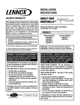
To Use the Vent Graph
1. Determinetheheightofthecenterofthehorizontalvent
pipe.UsingthisdimensionontheSidewallVentGraph,
locatethepointitintersectswiththeslantedgraphline.
2. Fromthepointofthisintersection,drawaverticallineto
thebottomofthegraph.
3. Selecttheindicateddimension,andpositiontheunitin
accordancewithsame.
EXAMPLE A:
Iftheverticaldimensionfromtheooroftheunitis35feet,the
horizontalruntotheouterwallangemustnotexceed6.5feet.
EXAMPLE B:
Iftheverticaldimensionfromtheooroftheunitis6.5feet,the
horizontalruntotheouterwallangemustnotexceed14.5
feet.
SPECIAL NOTE: Foreach45degreeelbowinstalledinthe
horizontalrun,thelengthofthehorizontalrunMUSTbe
reducedby18"(457mm).Thisdoesnotapplyifthe45degree
elbowsareinstalledontheverticalpartoftheventsystem.
Reduce3'forevery90°elbow.
Example:Accordingtothechartthemaximumhorizontalvent
lengthis20'andiftwo45degreeelbowsarerequiredinthe
horizontalventitmustbereducedto17'.
Themaximumnumberof45degreeelbowspermittedperside
wallinstallationistwo.Theseelbowscanbeinstalledineither
theverticalorhorizontalrun.
Note:Onverticalventingtherstelbowdoesnotgetcounted.
Acceptableverticalandhorizontalventrun.
(40'maximumverticaland20'maximumhorizontal)
Unacceptableverticalandhorizontalventrun.
Figure 22
Venting Graph (Dimensions in Feet)
VENTING FIREPLACE - TOP

31509-13-0416 Page 19
VENTING FIREPLACE - TOP (continued)
Below Grade Installation
Whenitisnotpossibletomeettherequiredventterminal
clearancesof12”(305mm)abovegradelevel,asnorkelkitis
recommended.Itallowsinstallationdepthdownto7”(178mm)
belowgradelevel.The7”(178mm)ismeasuredfromthecenter
ofthehorizontalventpipeasitpenetratesthroughthewall.
Ensure the sidewall venting clearances are observed. If
venting system is installed below ground, we recommend
a window well with adequate and proper drainage to be
installed around the termination area.
TYPICAL BASEMENT INSTALLATION
Figure 23
Examplesofpossibleventingsystemsusingone90°elbow.
Eightfeetislistedasminimumverticalventrunwith20feetof
maximumhorizontalventrun.Verticaldimensionsarebasedon
centerlinetocenterlineofpipe.Horizontaldimensionsarebased
oncenterlineofpipetoendoftermination.
Figure 24
Examplesofpossibleventingsystemsusingtwo90°elbows.
VislistedasminimumverticaldimensionsandH1+H2islisted
astotalofmaximumhorizontaldimensions.Themaximum
verticalandhorizontaldistancesfortwo90°elbowsasshownin
Figure 25 is20feet(6.1m).
Attention:RefertoFigure 22foradditionalventingrequirements.
Figure 25

31509-13-0416Page 20
VENTING FIREPLACE - TOP (continued)
Figure 27
Figure 28
FIREPLACE
SERIES
HARD ELBOW DIMENSIONS
"A" "B" "C" "D"
DVCD32FP
41-1/2"
(1054 mm)
4"
(102 mm)
6"
(152 mm)
91/8"
(232 mm)
DVCD36FP
41-1/2"
(1054 mm)
4"
(102 mm)
6"
(152 mm)
91/8"
(232 mm)
DVCD42FP
43-1/2"
(1105 mm)
4-1/2”
(114 mm)
6-1/2”
(165 mm)
91/8"
(232 mm)
FIREPLACE
SERIES
FLEX PIPE 90 DEGREE BEND
"A" "B" "C" "D"
DVCD32FP
43"
(1092 mm)
4-1/2"
(114 mm)
6-1/2"
(165 mm)
91/8"
(232 mm)
DVCD36FP
43"
(1092 mm)
4-1/2"
(114 mm)
6-1/2"
(165 mm)
91/8"
(232 mm)
DVCD42FP
45"
(1143 mm)
4-1/2"
(114 mm)
6-1/2"
(165 mm)
91/8"
(232 mm)
Figure 26
MINIMUM HOLE LOCATION DIMENSIONS FOR THROUGH
THE WALL HORIZONTAL INSTALLATIONS WITH 90 DEGREE
ELBOW OFF TOP OF FIREPLACE
SEE FIGURE 22 ON PAGE 18 FOR PERMISSIBLE "H" AND
"V" DIMENSIONS.
Positioning the Fireplace
Determinetheexactpositionoftheappliancesothedirect
ventterminationwillbecentered(ifpossible)betweentwo(2)
studs.Thiswillavoidanyextraframing.Allventkitpipesshould
beassembledontheunitaftertheunitismovedintothenal
position.
Cutting the Hole
Afterthereplacehasbeenpositionedinitspermanentlocation,
theholethroughtheexteriorwallofthehousecanbecut.
Thisholemustbe10"(254mm)highx10"(254mm)widewith
itscenterlinedeterminedbytheamountofverticalriseand
horizontalrunofthetermination.See Figure 26. Whenlocating
theholeitmustbenotedthatthebottomofthecapmustbe12"
(305mm)abovethegroundlevel,andtopofthecapmustbe
nolessthan18"(457mm)belowacombustibleprojection,and
nocloserthan9"(229mm)toanywallrunningparalleltovent
termination.See Figure 27.
/