IN-POOL STEPS
MODELS: IN-24 & IN-32
IMPORTANT INSTRUCTIONS: Read all instructions carefully & completely
to become familiar with parts, assembly, safety and proper use of this
product. Failure to follow these instructions may result in serious
personal injury. DO NOT DEVIATE FROM THESE INSTRUCTIONS
TOOLS REQUIRED: 7/16" socket or nut driver, measuring tape, Phillips
(star) screwdriver, utility / trimming knife or hand saw (you may need a
5/16" & 1/4" drill bits & drill)
SAFETY INSTRUCTIONS & PROPER USE
•
These pool step systems have a 300 lb load capacity - one person - when properly installed
•
The steps are designed and intended for use with an above ground pool only (flat bottom)
•
Your above ground pool has shallow water - absolutely NO DIVING or NO JUMPING into the pool
•
The steps conform to the latest revisions of the APSP & ANSI recommended standards for above
ground/on ground swimming pool steps (when properly assembled & installed as per manufacturer’s recommendations)
•
For entry & exit of the pool face steps at all times. Use extended handrails at all times for additional safety
•
These step systems are designed for use by one person at all times
•
Ensure the bottom of the side support stringers are free of debris & any possible sharp edges as not to damage the pool
liner. Use of a ladder or step pad (sold separately) is highly recommended for extra protection & life of the pool liner
•
Locate pool steps on a solid / flat base within the pool. These steps are NOT to be used with “dished” bottom pools
•
Secure step system to deck surface using BOTH sets of flanges included (front & rear) for stability and safety
•
Keep handrails and treads free from obstructions to avoid possible injury. Do not secure any items to the pool entry steps.
Such objects (eg. thermometers, play toys, ropes) may create a potential for tripping or entrapment & injury can occur
•
NEVER ALLOW CHILDREN TO SWIM UNATTENDED - Nothing replaces parental supervision at all times
•
Assemble and install this pool step system as per the manufacturer’s instructions. Do not deviate from these instructions
as serious personal injury or drowning may occur - PLEASE ALWAYS SWIM SAFELY & RESPONSIBLY !
•
Please review all instructions for proper use and safety with all individuals using these pool steps to prevent injury
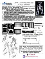
Step 1: IDENTIFY PARTS
Stringers - 2 pcs - 1 Left & 1 Right
Rear Deck
Flanges - 2 pcs
Front Deck
Flanges - 2 pcs
Upper Handrails - 4 pcs
2 Left & 2 Right
Lower Handrails - 2 pcs
1 Left & 1 Right
32" Tread-Riser - 1 pc
( with light hole)
32" Tread-Riser - 2 pcs
( without light hole)
32" Half Bottom Riser - 1 pc
32" Half Top Tread - 1 pc
TREAD - RISERS FOR 32" POOL STEPS
24" Tread-Riser - 2 pcs
( without light hole)
24" Half Btm Riser - 1 pc
24" Half Top Tread - 1 pc
24" Tread-Riser - 1 pc
( with light hole)
TREAD - RISERS FOR 24" POOL STEPS
R L

1-1/8"
3/4"
Step 2:
IDENTIFY HARDWARE
1/4 x 1-1/8"
Bolts - 6 pcs
1/4 x 3/4"
Bolts - 10 pcs
Washers
32 pcs
Hex Nuts
16 pcs
# 10 x 1"
Screws - 16 pcs
Step 3: FIT TREADS
& RISERS INTO
STRINGERS
Each of the tread riser parts is hollow and contains air. When manufactured, the tread risers have small holes pierced in them so when
the fully assembled step is placed within the pool the air can escape and the internal cavities will fill with water. This prevents the steps
from wanting to float in the pool. However, it does take time. If you wish to speed this process up and ensure your steps will fill with
water faster, you can drill an additional small hole (1/4") in the ends
of the tread risers (all parts) as shown in Detail 3.1 above
3.1
3.2
Each of the full tread risers is designed and manufactured to fold down the “center line” (indicated above in Details 3.2 & 3.3 with
arrows). The plastic material used in the manufacture of these parts is very flexible, however, temperature is an important factor on
how easily they will fold. The colder the material the harder it will be to fold the parts. HINT
: if you heat the entire “center line” of the
tread risers they will fold much easier. Using hot water, a heat gun or hair dryer or even laying the parts in the direct sunlight will
soften the plastic and allow them to fold easily. Make certain not to overheat the plastic - it can permanently mark or damage the parts
3.3
R
3.4 3.5 3.7
The fit and positioning of the treads and risers into the stringers is very specific. Each of the stringers has indentations with holes which
the ends of the treads and risers fit and lock into. The treads and risers have button lock knobs on the ends which fit through the holes
of the stringers and lock each part in place. Lay one right ( R ) stringer on a flat surface with the indentations facing up (Detail 3.4 &
3.5). The proper positioning of all treads and risers is outlined in Detail 3.6 & 3.7. Review this layout for correct positioning of all parts
1
2
3.6
3
4
5
1
2
3
Position 2 & 4 Position 3
Position 5 Position 1
Position 2 & 4 Position 3
Position 1 Position 5
24" TREAD
& RISER
PARTS
32" TREAD
& RISER
PARTS
WITH HOLE WITH HOLE
877-VINYL WK

3.11 3.15 3.12
3.6
3
4
5
1
2
Identify one of the half bottom riser parts. With the warning signs facing out, away from the steps, fit the bottom
riser into the indentation of the stringer at POSITION 1 (see Detail 3.6 & 3.8). Press the bottom riser into the
stringer until the button lock knob on the end protrudes through the hole and locks the part in place (see Detail
3.10). Identify one of the half top tread parts. With the anti-skid surface facing up, fit the top tread into the
indentation of the stringer at POSITION 5 (see Detail 3.6 & 3.9). Press the top tread into the stringer until the
button lock tabs on the end protrudes through the holes and locks the part in place (see Detail 3.10)
3.9 3.10 3.8
1
2
2
3.13 3.14
Identify one of the tread-riser parts (without light hole) and lay it on a flat surface. Holding the tread portion in place, fold the riser portion
over (see Details 3.11 - 3.13). Make certain to fold warning signs on riser portion toward anti-skid surface of tread portion. You can over fold
until portions touch as they will want to go back to their original position once you let go. Take the folded tread-riser and fit it into the
indentations of the stringer at POSITION 2 (see Detail 3.6, 3.14 & 3.15). Note: the tread portion with two button lock knobs will fit into
the horizontal indentation in the stringer just above the half bottom riser already installed. The riser portion will fit into the next indentation
above it. Press the tread-riser into the stringer until the button lock knobs on the ends protrude through the holes and lock the part in place
(see Detail 3.10). Similarly, take the tread-riser with light hole, fold the part and insert it into indentations at POSITION 3. Take the last
tread-riser (without light hole) and complete the assembly of the treads and risers. Make certain all button lock knobs secure parts in place
With all tread and riser parts securely installed within the right
stringer, position remaining left stringer (see Detail 4.1 & 4.2). With
the indentations in the left stringer fit over the ends of the treads and
risers, align the button lock knobs with the holes in the stringer and
press the stringer down locking all parts together. Make certain all
knobs are securely locked through stringer holes (see Detail 3.10).
Stand completed step assembly upright (see Detail 4.3). The top of
the stringers, where the upper handrails fit within, is open to the
internal hollow cavities. Your pool step requires additional weight for
ballast and to prevent the step from floating. Put approximately 10-15
lbs of clean gravel into both the left & right stringer. This will give
your fully assembled step system the required stability with the pool
Step 4: FIT REMAINING STRINGER & ADD WEIGHT
4.2 4.1
4.3
4.4
FOLLOW ALL ASSEMBLY INSTRUCTIONS FOR A
SAFE AND STABLE POOL STEP SYSTEM.
USE OF A STEP PAD IS HIGHLY RECOMMENDED

RIGHT
IN
LINE
VISIT OUR WEBSITE FOR PRODUCT WARRANTY REGISTRATION
Measure depth of pool (inside pool) to the height of the pool
deck (see 7.1 & 7.2). Transfer this measurement to the upper
handrails to connect to deck surface (see 7.3). Cut excess
upper handrails if required. Slide rear flanges (see 7.4) onto
handrails and position step system into the pool. Make certain
the step rests firmly on pool floor & is pulled tight against the
pool deck or pool top rail to minimize the gap between step &
pool wall (see 7.2). Secure all flanges to deck surface using
the 1" screws provided (see 7.4-7.6). Drill through the center
of rear flanges & handrail and secure using a 3/4" bolt,
washer both sides and nut (see 7.5). Repeat for both flanges.
Make certain step is secure before using. Step is to be
removed when winterizing your pool. Review all instructions
for proper use with all individuals using this product
x"
7.1
Step 5: ASSEMBLE
UPPER HANDRAILS
LEFT
Identify the upper RIGHT (R) & LEFT (L) handrails (small stamp in parts - see Detail
5.1 & 5.2). Fit handrail pair together as shown in Detail 5.3-5.5 aligning bolt holes at
top. Secure using 1-1/8" bolts, washers both sides and nuts. Tighten hardware.
Repeat for both sets of upper handrails. Slide front deck flanges over upper handrails
before fitting handrails into assembled step (see Detail 5.6 & 5.7). Make certain
flanges face proper direction (inward). One flange goes over a RIGHT handrail and
one over a LEFT. Fit handrail ends (with flanges on) into openings at the top of
stringers as shown in Detail 5.7. Make certain location is correct (R & L as per 5.7)
5.1
5.2
5.3 5.4
5.5
R
R
L
5.7
L R
5.6
Step 6: ASSEMBLE LOWER HANDRAILS
6.1
6.2
6.3
6.4 6.5 6.6
Identify the lower RIGHT & LEFT handrails (small stamp in parts - Detail 6.1). Facing
step as if the climb, position right handrail on the right side and left on the left side. Align
the bolt flanges on the handrails with the bolt flanges on the stringers and upper hand-
rails (see Detail 6.2-6.5). It is important to start with the connection point with the upper
handrail (Detail 6.3). Align bolt holes by sliding upper handrail up or down. Once aligned,
make certain the upper and lower handrails are perfectly aligned (Detail 6.4). Secure
connection using 3/4" bolt, washer both sides and nut. Repeat for all connection points
on both handrails. After handrails secured, secure upper handrails with stringers using
same hardware (Detail 6.6). Drill a 5/16" hole if bolt holes don’t perfectly align
Step 7: POSITION
STEP & SECURE
TO DECK SURFACE
DECK
x"
7.3
7.2
7.5 7.4
7.6
www.vinylworkscanada.com
/