HomeSelects 2052 Installation guide

Category
Household fans
Type
Installation guide

HomeSelects 2052 is a ceiling fan designed for indoor use, featuring both flush mount and suspended installation options. It comes with a 52-inch blade span, making it suitable for medium to large rooms. The fan can be operated using pull chains or switches mounted on the fan itself. It has a reversible motor, allowing for both cooling and heating functions. Additionally, the fan includes a light kit with three bulbs for providing illumination.

HomeSelects 2052 is a ceiling fan designed for indoor use, featuring both flush mount and suspended installation options. It comes with a 52-inch blade span, making it suitable for medium to large rooms. The fan can be operated using pull chains or switches mounted on the fan itself. It has a reversible motor, allowing for both cooling and heating functions. Additionally, the fan includes a light kit with three bulbs for providing illumination.

2
5($' $1' 6 $ 9 ( 7+(6( ,16758&7,216
%HIRUH EHJLQQLQJ LQVWDOODWLRQ
RI\RXU QHZ
FHLOLQJ
IDQ
UHDG DQG IROORZWKHVH VDIHW\SUHFDXWLRQV,I\RX DUHQRWIDPLOLDU
ZLWKQDWLRQDODQGORFDOHOHFWULFDOFRGHVDQGEDVLFHOHFWULFDO
ZLULQJ
SURFHGXUHV
ZH UHFRPPHQG
WKDW\RX KDYH DTXDOLILHG
HOHFWULFLDQ
LQVWDOO
\RXU QHZ FHLOLQJ
IDQ
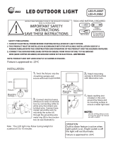
Before you begin, TURN OFF THE ELECTRICITY. Determine which cir-
cuit your new fan will be using and remove the fuse or turn off the circuit
breaker at the main electrical panel.
Make sure that all wiring conforms to national and local electrical codes. If
you are in question, obtain a copy of the codes and wire the fan according-
ly. Never leave bare wires uncovered (wire connection), use wire nuts to
cap all connections. Plastic electrical tape is not recommended.
When working with electricity, never take short cuts. Follow the code in
every respect. Basic requirements for a ceiling fan installed with lights are,
120 volts AC - 60Hz, on a grounded circuit with a 15 amp breaker or fuse.
Make sure that your electrical system and choice of location meet these
requirements.
If the location where you plan to install your fan does not already have an
electrical outlet, hire a licensed electrician to run the wiring and install an
outlet box designed for ceiling fans or heavy fixtures. The outlet box
should be able to support a minimum moving weight of 50 pounds and
marked “Acceptable for Fan Support” (Plastic outlet boxes are not recom-
mended for ceiling fan installation).
If you plan to use an existing electrical location, check to make sure that the
outlet box is not PLASTIC, that it is securely attached and able to support
at least 50 pounds of moving weight and marked “Acceptable for Fan
Support”. If you have any questions, outlet boxes and support systems for
ceiling fans are available at most hardware and do-it-yourself centers. In
most cases, your
dealer will have all the necessary products
for the proper
and safe installation of your ceiling fan.
The location you choose should have a minimum clearance of 20 inches
from any wall to the blade tip at any point in its rotation and a minimum of
7 feet from blade level to floor and 10 inches from the blades.
3
Look for Me!
I have safety Tips and
Ideas for installation
These instructions are designed for a number of similar but different ceiling fans. As you
proceed, some steps may or may not apply to the fan you purchased. Compare each step or
optional procedure to your fan and proceed accordingly.
This ceiling fan was not designed for installation in any location where it
might be exposed to moisture or high humidity. Installation in this type of
location could be UNSAFE, will most likely damage the fan and its finish...
and will VOID YOUR WARRANTY.
Every effort has been made to provide you with proper instructions for the
safe installation of this ceiling fan. You could however, encounter situa-
tions or problems not covered in this manual. Should this occur, please
refer to a do-it-yourself wiring handbook or hire a qualified electrician to
install your fan.
Never attach the blades to your ceiling fan before the fan body is properly
mounted on the ceiling.
Lubrication of your new ceiling fan is not necessary. The ball bearings have
been adequately charged with grease and permanently sealed at the factory
so that, under normal conditions, further attention is not necessary.
To reduce the risk of fire, electrical shock, or personal injury,
mount this fan to an outlet box marked “Acceptable for Fan
Support” and use the Mounting Screws provided with the outlet
box. CAUTION: Install the primary mounting means and use
only the hardware provided with the fan.
To reduce the risk of personal injury take care not to bend the
blade carriers. Be careful not to insert foreign objects into rotat-
ing fan blades.
The important safeguards and instructions appearing in this
manual are not meant to cover all possible conditions and situa-
tions that may occur. It must be understood that common sense,
caution and careful attention to detail are factors which cannot be
built into this product. These factors must be supplied by the
person or persons installing, caring for, and operating the unit.
4
)LJ
)LJ
)LJ
Step 1 Attach the mounting bracket
Bend the electrical wires up
and back out of the way with
the black wire to one side and
the white and ground wire
tothe other side. The wires
should be off to the side and up
against ceiling.
Remove the two non-slotted mounting screws on
the top of the canopy. Back the two slotted
screws out about half way. This will enable you
to remove the mounting bracket from canopy
(see figure 1).
Install the mounting bracket on the electrical
junction box in the ceiling using two machine
screws, two washers and two lock washers (see
figure 2).
The mounting bracket has slotted holes to enable
it to move sideways for proper alignment. Make
sure the mounting bracket is centered over the
electrical junction box and that it is securely
attached (see figure 3).
If you are using an extended support rod, (longer
than the one supplied with your fan) remove the
half ball from the small support rod that came
with the fan and put it on the extended support
rod. Make sure to retighten the set screw and
insert the safety screw (see figure 2-2).
Have you
TURNED OFF
the Electricity?
NO MOVEMENT SHOULD OCCUR
BETWEEN THE MOUNTING BRACKET
AND THE ELECTRICAL JUNCTION BOX.
-XQFWLRQ%R[
0RXQWLQJ%UDFNHW
0RXQWLQJ%UDFNHW
1RQ6ORWWHG
6FUHZ
6ORWWHG6FUHZ
:DVKHU
:DVKHU
6FUHZ
&DQRS\
W
-XQFWLRQ%R[
+DQJHU
EHIDFLQJXSVLGH
RSHQLQJPXVW
)LJ
5
)LJ
)LJ
Step 3 Attach the support assembly
This fan is designed to be mounted as a flush mount
(for lower ceiling heights), or suspended.
Flushmount (see figure 4)
Loosen the set screws (2) in the support rod coupler
located on the top center of the motor housing until
the inside channel is clear.
Remove and save the safety screw from the coupler.
Place the ceiling canopy on top of the motor housing
and secure with the three mounting screws.
Suspended (see figure 5)
Loosen the set screws (2) in the support rod coupler
located on the top center of the motor housing until
the inside channel is clear.
Remove and save the safety screw from the coupler.
Place the ceiling canopy face down (small end) over
the support rod coupler on the motor housing.
Slide canopy onto support rod.
Feed the electrical wires from the fan housing
through the support rod.
Thread the support rod into the support rod coupler
until the safety screw can be inserted through the
hole in both the rod and coupler.
Insert the safety screw through the hole in the
support rod coupler and support rod then tighten
firmly.
Insert the set screw in the coupler and tighten
firmly.
&HLOLQJ&DQRS\
6FUHZV
6XSSRUW5RG&RXSOHU
7KUX3LQ
+DQJHU%DOO
6HW6FUHZ
6XSSRUW5RG
&RWWHU3LQ
6DIHW\3LQ
6HW6FUHZ
0RWRU&RXSOHU
6
)LJ
*URXQG:LUH
6XSSRUW5RG
0RXQWLQJ
%UDFNHW
%DOO+DQJHU
0RXQWLQJ
%UDFNHW
.H\ZD\3LQ
%DOO+DQJHU
6XSSRUW5RG
)LJ
)LJ
Step 4 Hanging the Fan Body
NOTE: Suspended Installation (follow steps
1-4), Flushmount Installation (go to step 4)
1 - Notice the half ball on the end of the support
rod is grooved down one side. This Keyway fits
over the small keyway pin on the inside of the
mounting bracket and keeps the ceiling fan from
spinning on the mounting bracket.
2 - Using your step ladder, lift the fan and place
the half ball in the center of the mounting bracket
with the keyway pin inserted into the keyway on
the ball. Turn the fan left and right slightly to
make sure it is seated on the bracket with the
keyway pin in the keyway (see figure 6).
3 - Trim the lead wires, leaving about six inches of
each wire extending from the support rod (see
figure 7).
4 - Slide the ceiling canopy up into place over the
ceiling mounting bracket. Loosen up the canopy
screws on the side of the mounting bracket. Line
up the J Slots with the canopy screws. Press the
canopy against the mouting bracket and turn it
clockwise. Tighten screws on the J Slots and
install the two screws in the remaining holes (see
figure 8).
Depending on how deep the
electrical junction box was
installed in the ceiling, you
may have a slight gap between
the ceiling canopy and the
ceiling.
Junction boxes are commonly
installed at different depths in
the ceiling, so we have
designed the mounting bracket
and canopy to allow for this.
&DQRS\
%OXH
:KLWH
:KLWH
%ODFN
%ODFN
*URXQG
*URXQG
7
)LJ
)LJ
Step 5 Making the Electrical Connections
To operate your ceiling fan with the pull chain(s)
and switches mounted on your fan, follow the
instructions below:
Attach the GREEN wire (connected to the half
ball) to the GROUND wire in the junction box.
The GROUND wire is usually a bare copper wire
without plastic insulation. It could also be
covered in green plastic insulation (see figure 9).
Attach the BLACK wire and the BLUE wire
from the ceiling fan to the BLACK wire in the
junction box.
Attach the WHITE wire from the fan to the
WHITE wire in the junction box.
Fold the connected wires (see figure 10) and push
them up inside the electrical junction box with the
black and blue wires to one side and the white and
green to the other side. Make sure the wire nuts
do not come loose during this operation.
Each of the above connec-
tions should be made as tight
as possible using the proper
size plastic wire nuts. Plastic
electrical tape is not recom-
mended for these connec-
tions.
%ODFN
%OXH
:KLWH
*UHHQ*URXQG
8
)LJ
)LJ
%ODGH
6FUHZ
%ODGH$UP
: DVKHU
0RWRU+RXVLQJ
Step 6 Fan Blade and Blade Arm Assembly
Step 7 Fan Blade Assembly Installation
Remove the large screws in the face of the motor.
Discard any rubber blocks attached to these
screws. The rubber blocks are installed at the
factory to stabilize the motor during shipment.
Attach each blade to the motor face using pre-
installed screws (see figure 12). Take care not to
bend the blade arms during installation. This
will cause your fan to wobble while running.
Attach each fan blade to a blade arm with
three 3/16” x 7.5 mm blade screws and three
3/16” fiber washers (see figure 11). DO NOT
OVER TIGHEN THESE SCREWS.
Screws should be tightened until the washers
are compressed by the screw head. Hold the
Blade Arm decorative side down and place
the blade on top with the flat side of the blade
facing down. Each screw is passed through
the washer and blade and screwed into the
blade arm.
Try mounting the blades on
opposing sides of the motor
face, This will help keep the
fan more level during blade
installation.
9
)LJ
)LJ
Step 8 Light Fixture Installation
Step 9 Installing Glass Shades and Bulbs
Step 10 Final Checks
Each of the above connections
should be made as tight as
possible using the proper size
plastic wire nuts. Plastic elec-
trical tape is not recommended
for these connections.
6FUHZV
/LJKW)L[WXUH
:LUH1XWV
7KUHH6SHHG
6ZLWFKSXOOFKDLQ
*ODVV6KDGHV
7KXPE6FUHZV
/LJKW)L[WXUH
6ZLWFKSXOOFDLQ
5HYHUVH6ZLWFK
%XOXV
Back off (loosen) the three screws on the electrical
housing cover (see figure 13).
Connect White wire to White wire, and Black wire
to Blue wire using quick connectors. Press
together firmly.
Place light fixture onto fan, line up the 2 holes and
rotate light fixture; Insert the screws and tighten.
Place glass shades onto light fixture, Secure with
thumb screws, DO NOT over tighten (see figure
14).
Twist bulbs into socket, DO NOT over tighten.
Check all set screws and connections are properly
in place and tight.
Check blade clearance and rotation.
Attach the decorative pull chain tassel(s) to the
switch housing.
10
Figure 15 illustrates the wiring used to control
the fan with a wall switch plus an optional light
fixture controlled at the fixture.
Figure 16 illustrates the wiring used to control
fan with the pull chain on the electrical switch
housing plus an optional light fixture with a wall
switch.
Figure 17 illustrates the wiring used to control
the fan and optional light fixture with separate
wall switches.
Optional Wiring Diagrams
If you elect to control the motor of your ceiling
fan from a wall switch, remember that the wall
switch will only turn your fan ON or OFF. The
speed can be adjust at the fan.
If you elect to control the speeds of your ceiling
fan from a wall switch, YOU MUST set the
speed switch on the ceiling fan to HIGH speed
and leave it in that setting.
IMPORT
ANT NOTE:
ONLY USE AN OPTIONAL WALL
SWITCH THAT HAS BEEN DESIGNED
FOR USE WITH CEILING FANS
)DQ FRQWUROOHGDWIDQZLWK/LJKWFRQWUROOHGDWZDOOVZLWFK
)DQ FRQWUROOHGZLWKZDOOVZLWFKDQG /LJKWFRQWUROOHGDWIDQ
)DQ /LJKWVFRQWUROOHGE\ZDOOVZLWFKRUVZLWFKHV
)LJ
)LJ
)LJ
FAN
LIGHT
FAN
LIGHT
FAN
LIGHT
11
Operation Instructions
Your new
ceiling fan is now ready for use. Reset your
circuit breaker and restore power to the circuit. See the Operation
Instructions below to review the function of each control on your
fan.
The three speed pull chain located on the switch housing (see
figure 13) controls the speed of your fan. When the fan is OFF,
pull the chain once for HIGH speed, twice for MEDIUM speed,
three times for LOW speed and fourth time to turn it off again.
The light fixture pull chain located on the bottom of the light fix-
ture (see figure 14) controls your light kit in "ON" or "OFF".
The slide switch located on the switch housing (see figure 14) con-
trols the direction of blade rotation. The UP position sets the
blades in REVERSE rotation (air moves UP). The DOWN posi-
tion sets the blades in FORWARD rotation (air moves DOWN).
Maintenance
Your fan requires very little maintenance. Cleaning
of the housing should be done with a damp soft
cloth (NO CLEANING AGENTS). On the blades,
use a duster or dry cloth because any moisture could
cause the blades to warp.
12
6XSSRUW5RG
6ZLWFK+RXVLQJ
0RWRU$VVHPEO\
6DIHW\3LQ
%ODGH6FUHZV
DQG /RFN: DVKHUV
6ZLWFK+RXVLQJ 6FUHZ
/LJKW)L[WXUH
%XOEV
*ODVV6KDGHV
&RWWHU3LQ
%ODGH
&HLOLQJ&DQRS\
&DQRS\6FUHZV
5HYHUVH 6ZLWFK
%ODGH$UP
0RXQWLQJ%UDFNHW
0RWRU&RXSOHU
7KXPE6FUHZV
7KUHH6SHHG 6ZLWFK
SXOOFKDLQ
/LJKW6ZLWFKSXOO
FKDLQ
  • Page 1 1
  • Page 2 2
  • Page 3 3
  • Page 4 4
  • Page 5 5
  • Page 6 6
  • Page 7 7
  • Page 8 8
  • Page 9 9
  • Page 10 10
  • Page 11 11
  • Page 12 12

HomeSelects 2052 Installation guide

Category
Household fans
Type
Installation guide

HomeSelects 2052 is a ceiling fan designed for indoor use, featuring both flush mount and suspended installation options. It comes with a 52-inch blade span, making it suitable for medium to large rooms. The fan can be operated using pull chains or switches mounted on the fan itself. It has a reversible motor, allowing for both cooling and heating functions. Additionally, the fan includes a light kit with three bulbs for providing illumination.

Ask a question and I''ll find the answer in the document

Finding information in a document is now easier with AI