
Operator’s Manual
Mobile Generator
G70, G100
G130, G150
Type G70, G100, G130, G150
Document 5100027027
Date 0919
Revision 07
Language EN
5100027027

Copyright notice
© Copyright 2019 by Wacker Neuson Production Americas LLC
All rights, including copying and distribution rights, are reserved.
This publication may be photocopied by the original purchaser of the
machine. Any other type of reproduction is prohibited without express
written permission from Wacker Neuson Production Americas LLC.
Any type of reproduction or distribution not authorized by Wacker
Neuson Production Americas LLC represents an infringement of valid
copyrights. Violators will be prosecuted.
Trademarks
All trademarks referenced in this manual are the property of their
respective owners.
Manufacturer
Wacker Neuson Production Americas LLC
N92W15000 Anthony Avenue
Menomonee Falls, WI 53051 U.S.A.
Tel: (262) 255-0500 · Fax: (262) 255-0550 · Tel: (800) 770-0957
www.wackerneuson.com
Original instructions
This Operator’s Manual presents the original instructions. The original
language of this Operator’s Manual is American English.

wc_tx004643en.fm 3
CALIFORNIA Proposition 65 Warning
CALIFORNIA Proposition 65 Warning
WARNING
The engine exhaust from this product contains chemicals known to the State of
California to cause cancer, birth defects, or other reproductive harm.
WARNING
Diesel engine exhaust and some of its constituents are known to the State of
California to cause cancer, birth defects, and other reproductive harm.
WARNING
Cancer and Reproductive Harm -
www.P65Warnings.ca.gov.
WARNING
Batteries, battery posts, terminals and related accessories contain lead and lead
compounds, and other chemicals known to the State of California to cause cancer
and birth defects or other reproductive harm. WASH HANDS AFTER HANDLING.

CALIFORNIA Proposition 65 Warning Proposition 65 Warning
4 wc_tx004643en.fm
This page is intentionally left blank.

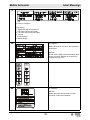
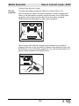
Mobile Generator Machine Identification
wc_tx004281gb_FM10.fm 5
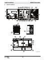
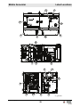
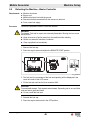
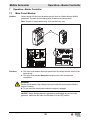
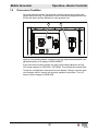
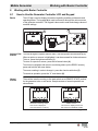
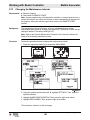
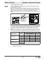
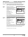
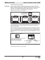
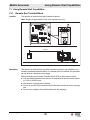
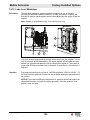
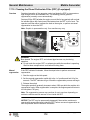
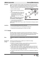
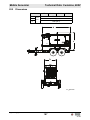
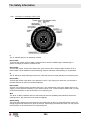
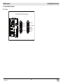
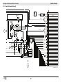
Machine Identification
SAVE THESE INSTRUCTIONS—This manual contains important instructions for
the machine models below. These instructions have been written expressly by
Wacker Neuson Production Americas LLC and must be followed during installation,
operation, and maintenance of the machines.
Machine
identification
A nameplate listing the model number, item number, revision number, and serial
number is attached to this machine. The location of the nameplate is shown above.
Serial number
(S/N)
For future reference, record the serial number in the space provided below. You will
need the serial number when requesting parts or service for this machine.
Machine Item Number
G70 5200023226, 5200023227, 5200023228, 5200023974, 5100018635,
5100021959, 5100036306
G100 5100033310, 5100033311, 5100033312, 5100036307, 5100045086,
5100045498, 5100045499, 5100045553, 5100045554, 5100045555,
5100049835, 5100049836, 5100049837
G130 5200023232, 5200023233, 5200023234, 5100018637, 5100022091,
5100036308, 5100045087, 5100045559, 5100045560, 5100045564,
5100045565, 5100045566, 5100049838, 5100049840
G150 5200022870, 5200023235, 5200023236, 5200023237, 5100018638,
5100022092, 5100036309, 5100049841, 5100049842, 5100049843
wc_gr013470
R
Serial Number
159047
hz
215429
For electrical
equipment only.
Pour material
electrique
seulement.
amb.temp.
Rev.
Type/Model
Item Number
rpm
lbs
PRIME RATING
kW/
kVA
V
A
kg
MADE
IN USA
Serial Number:

Foreword Mobile Generator
6 wc_tx004282gb_FM10.fm
Foreword
Machine
documentation
■ From this point forward in this documentation, Wacker Neuson Production
Americas LLC will be referred to as Wacker Neuson.
■ Keep a copy of the Operator’s Manual with the machine at all times.
■ For spare parts information, please see your Wacker Neuson Dealer, or visit the
Wacker Neuson website at http://www.wackerneuson.com/.
■ When ordering parts or requesting service information, be prepared to provide
the machine model number, item number, revision number, and serial number.
Expectations
for
information in
this manual
■ This manual provides information and procedures to safely operate and
maintain the above Wacker Neuson model(s). For your own safety and to
reduce the risk of injury, carefully read, understand, and observe all instructions
described in this manual.
■ Wacker Neuson expressly reserves the right to make technical modifications,
even without notice, which improve the performance or safety standards of its
machines.
■ The information contained in this manual is based on machines manufactured
up until the time of publication. Wacker Neuson reserves the right to change any
portion of this information without notice.
■ The illustrations, parts, and procedures in this manual refer to Wacker Neuson
factory-installed components. Your machine may vary depending on the
requirements of your specific region.
CALIFORNIA
Proposition
65 Warning
Combustion exhaust, some of its constituents, and certain vehicle components
contain or emit chemicals known to the State of California to cause cancer and
birth defects or other reproductive harm.
Laws
pertaining to
spark
arresters
NOTICE: State Health Safety Codes and Public Resources Codes specify that in
certain locations spark arresters be used on internal combustion engines that use
hydrocarbon fuels. A spark arrester is a device designed to prevent accidental
discharge of sparks or flames from the engine exhaust. Spark arresters are
qualified and rated by the United States Forest Service for this purpose. In order to
comply with local laws regarding spark arresters, consult the engine distributor or
the local Health and Safety Administrator.

Mobile Generator Foreword
wc_tx004282gb_FM10.fm 7
Manufacturer’s
approval
This manual contains references to approved parts, attachments, and
modifications. The following definitions apply:
■ Approved parts or attachments are those either manufactured or provided by
Wacker Neuson.
■ Approved modifications are those performed by an authorized Wacker
Neuson service center according to written instructions published by Wacker
Neuson.
■ Unapproved parts, attachments, and modifications are those that do not
meet the approved criteria.
Unapproved parts, attachments, or modifications may have the following
consequences:
■ Serious injury hazards to the operator and persons in the work area
■ Permanent damage to the machine which will not be covered under warranty
Contact your Wacker Neuson dealer immediately if you have questions about
approved or unapproved parts, attachments, or modifications.
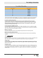
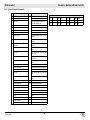
Abbreviations
Abbreviation or
Acronym
Definition
Abbreviation
or Acronym
Definition
ATS Automatic transfer switch L3 Level load logic
CARB California Air Resource
Board
LT Light truck
CDL Commercial driver’s license MAF Mass air flow
CKP Crank position NC Normally closed
CMP Camshaft position NHTSA National Highway Traffic Safety
Administration
CO Carbon monoxide NOx Nitrogen oxides
DEF Diesel exhaust fluid P/L Pressure limiter
DM Dosing module PPE Personal protective equipment
DOC Diesel oxidation catalyst S/N Serial number
DTC Diagnostic trouble codes SCR Selective catalytic reduction
EGR Exhaust gas recirculation SPN Suspect parameter number
EPA Environmental Protection
Agency
ST Special trailer
ERT Extended run tank TDG Canadian Transportation of
Dangerous Goods Act
FMI Failure mode identifier TWI Treadwear indicators
GAWR Gross axle weight ratings VCW Vehicle capacity weight
IBC Intermediate bulk container — —

Foreword Mobile Generator
8 wc_tx004282gb_FM10.fm
This page is intentionally left blank.

Table of Contents
Mobile Generator
wc_bo5100027027_07TOC.fm
9
CALIFORNIA Proposition 65 Warning 3
Machine Identification 5
Foreword 6
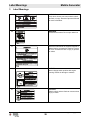
1 Safety Information 15
1.1 Signal Words Used in this Manual ............................................................. 15
1.2 Machine Description and Intended Use ..................................................... 16
1.3 Safety Guidelines for Operating the Machine ............................................. 17
1.4 Service Safety ............................................................................................ 18
1.5 Operator Safety while Using Internal Combustion Engines ....................... 20
1.6 Safety Guidelines for Mobile Generators ................................................... 21
1.7 Safety Guidelines for Towing the Machine ................................................. 22
1.8 Safety Guidelines for Lifting the Machine ................................................... 23
1.9 Reporting Safety Defects ........................................................................... 23
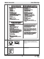
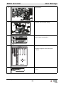
2 Label Locations 24
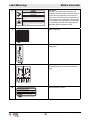
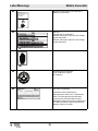
3 Label Meanings 26
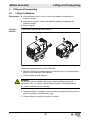
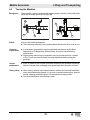
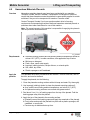
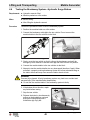
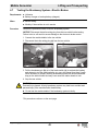
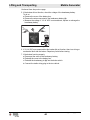
4 Lifting and Transporting 37
4.1 Lifting the Machine ..................................................................................... 37
4.2 Before Towing Checklist ............................................................................. 38
4.3 Towing the Machine ................................................................................... 39
4.4 Preparing the Machine for Transport on a Truck or Trailer ........................ 40
4.5 Hazardous Materials Placards ................................................................... 41
4.6 Testing the Breakaway System—Hydraulic Surge Brakes ......................... 42
4.7 Testing the Breakaway System—Electric Brakes ...................................... 43
5 Machine Setup 45
5.1 Preparing the Machine for First Use ........................................................... 45
5.2 Positioning the Machine ............................................................................. 46
5.3 Grounding the Generator ........................................................................... 47
5.4 Recommended Fuel ................................................................................... 48
5.5 Refueling the Machine—Basler Controller ................................................. 49
5.6 Refueling the Machine—Deep Sea Controller ........................................... 50

Table of Contents
Mobile Generator
wc_bo5100027027_07TOC.fm
10
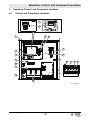
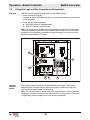
6 Operation, Control, and Component Locations 51
6.1 Control and Component Locations ............................................................. 51
7 Operation—Basler Controller 53
7.1 Main Circuit Breaker ................................................................................... 53
7.2 Engine Start Switch .................................................................................... 55
7.3 Generator Pre-Alarms and Alarms (Shut-Down Conditions) ...................... 56
7.4 Overcurrent Condition ................................................................................ 57
7.5 Using the Lugs and the Convenience Receptacles .................................... 58
7.6 Selecting the Voltage ................................................................................. 59
7.7 Wet Stacking .............................................................................................. 61
7.8 Before Starting the Machine ....................................................................... 62
7.9 Starting and Running the Machine ............................................................. 63
7.10 Stopping the Machine ................................................................................. 66
7.11 Emergency Stop Switch ............................................................................. 66
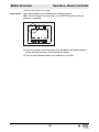
7.12 LCD Panel: Monitoring Machine Operation ................................................ 67
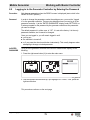
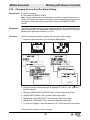
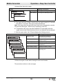
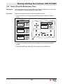
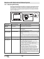
8 Working with Basler Controller 69
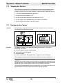
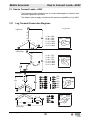
8.1 How to Use the Generator Controller LCD and Keypad ............................. 69
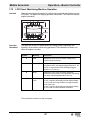
8.2 Menu Diagram of the Generator Controller ................................................ 70
8.3 Menu Diagram Components ...................................................................... 71
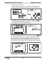
8.4 Using the Metering and Settings Menus .................................................... 72
8.5 Logging in to the Generator Controller by Entering the Password ............. 73
8.6 Adjusting the LCD Screen Contrast ........................................................... 76
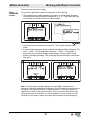
8.7 Changing the Time/Date Settings .............................................................. 77
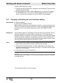
8.8 Changing the Sender Fail Time Delays ...................................................... 78
8.9 Changing the Units of Measure .................................................................. 80
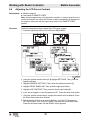
8.10 Changing the Low Fuel Pre-Alarm Setting ................................................. 81
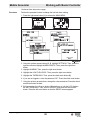
8.11 Changing or Disabling the Low Fuel Alarm Setting .................................... 82
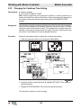
8.12 Changing the Cooldown Time Setting ........................................................ 84
8.13 Changing the Maintenance Interval ............................................................ 86
8.14 Resetting the Maintenance Interval Pre-Alarm ........................................... 88
8.15 Resetting a Loss of Voltage Pre-Alarm ...................................................... 89
8.16 Accessing and Using the Event Log ........................................................... 90

Table of Contents
Mobile Generator
wc_bo5100027027_07TOC.fm
11
9 Operation—Deep Sea Controller 92
9.1 Main Circuit Breaker ................................................................................... 92
9.2 Generator Controller Power Switch ............................................................ 93
9.3 Selecting the Voltage ................................................................................. 94
9.4 Wet Stacking .............................................................................................. 96
9.5 Deep Sea Controller Buttons/Functions ..................................................... 97
9.6 Generator Controller Alarms and Shut-Down Conditions ........................... 99
9.7 Before Starting the Machine ..................................................................... 101
9.8 Starting and Running the Generator ........................................................ 102
9.9 Stopping the Generator ............................................................................ 104
9.10 Emergency Stop Switch ........................................................................... 105
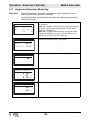
9.11 Engine and Generator Monitoring ............................................................ 106
10 Working with Deep Sea Controller: DSE 7310 MKII 107
10.1 Introduction ............................................................................................... 107
10.2 Navigating the Menus ............................................................................... 108
10.3 Adjusting Screen Contrast ........................................................................ 110
10.4 How to Reset the Maintenance Timer ...................................................... 111
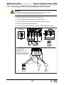
11 How to Connect Loads—480V 112
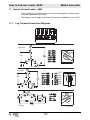
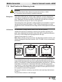
11.1 Lug Terminal Connection Diagrams ......................................................... 112
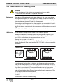
11.2 Best Practices for Balancing Loads .......................................................... 113
11.3 Connecting 480V, 3-Phase and Single-Phase Loads .............................. 116
11.4 Connecting a 240V 3Ø Load and a 240V 1Ø Load .................................. 117
11.5 Connecting 240V and 120V Single-Phase Loads .................................... 118
11.6 Connecting a 208V 3Ø Load and Multiple 120V 1Ø Loads ...................... 119
11.7 Connecting a 220–240V 3Ø Load and Multiple 127–133V 1Ø Loads ...... 120
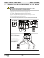
12 How to Connect Loads—600V 121
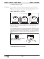
12.1 Lug Terminal Connection Diagrams ......................................................... 121
12.2 Best Practices for Balancing Loads .......................................................... 122
12.3 Connecting a 240V 3Ø Load and a 240V 1Ø Load .................................. 125
12.4 Connecting 240V and 120V Single-Phase Loads .................................... 126
12.5 Connecting a 208V 3Ø Load and Multiple 120V 1Ø Loads ...................... 127
12.6 Connecting a 220–240V 3Ø Load and Multiple 127–133V 1Ø Loads ...... 128
12.7 Connecting 480V, 3-Phase Loads ............................................................ 129
12.8 Connecting 600V, 3-Phase Loads ............................................................ 130

Table of Contents
Mobile Generator
wc_bo5100027027_07TOC.fm
12
13 Using Remote Start Capabilities 131
13.1 Remote Run Terminal Block .................................................................... 131
13.2 Remote Transfer Switch ........................................................................... 132
13.3 Preparing for Automatic/Remote Start-Up—Deep Sea ............................ 133
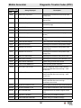
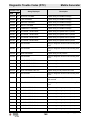
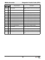
14 Diagnostic Trouble Codes (DTC) 135
14.1 Accessing DTCs with the Basler Controller .............................................. 135
14.2 Accessing Engine DTCs using the Deep Sea Controller ......................... 136
14.3 List of Engine Diagnostic Trouble Codes (DTCs) ..................................... 137
15 Factory-Installed Options 150
15.1 Battery Charger ........................................................................................ 150
15.2 Lockable Battery Disconnect .................................................................... 151
15.3 Camlocks .................................................................................................. 152
15.4 Containment System ................................................................................ 153
15.5 Extended Run Tank (ERT) ....................................................................... 153
15.6 Engine Block Heater ................................................................................. 154
15.7 Cold-Weather Thermostat ........................................................................ 154
15.8 Low Coolant Shutdown ............................................................................ 155
15.9 Temperature-Activated Shutters .............................................................. 156
15.10 Positive Air Shutoff Valve ......................................................................... 157
15.11 Connecting an External Fuel Supply ........................................................ 158
15.12 Lube Level Maintainer .............................................................................. 159
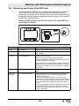
16 Machines with Aftertreatment Exhaust System 160
16.1 How the Aftertreatment Exhaust System Works ...................................... 160
16.2 Filling the DEF Tank ................................................................................. 161
16.3 Shelf Life of Diesel Exhaust Fluid (DEF) .................................................. 162
16.4 Monitoring and Control of the DEF Level ................................................. 163
16.5 Monitoring DEF Quality ............................................................................ 164
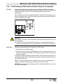
16.6 Conditioning the Aftertreatment Exhaust System (if equipped) ................ 165
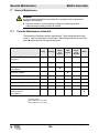
17 General Maintenance 166
17.1 Periodic Maintenance Schedule ............................................................... 166
17.2 Maintaining the Emission Control System ................................................ 167
17.3 Preparing for Maintenance ....................................................................... 167
17.4 Cleaning the Machine ............................................................................... 167

Table of Contents
Mobile Generator
wc_bo5100027027_07TOC.fm
13
17.5 Inspecting the Machine ............................................................................ 168
17.6 Maintaining the Trailer .............................................................................. 168
17.7 Checking and Draining the Containment System (if equipped) ................ 169
17.8 Checking the Exhaust System ................................................................. 170
17.9 Maintaining the Battery ............................................................................. 171
17.10 Cleaning the Diesel Particulate Filter (DPF) (if equipped) ........................ 172
17.11 Filling the Radiator ................................................................................... 173
17.12 Replacing the Aftertreatment DEF Dosing Unit Filter (if equipped) .......... 174
17.13 Storage ..................................................................................................... 175
17.14 Machine Disposal and Decommissioning ................................................. 176
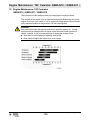
18 Engine Maintenance: T4F Cummins
QSB5-G10 / QSB5-G11 / QSB5-G12 178
18.1 Coolant Recommendations and Specifications ........................................ 182
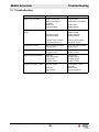
19 Troubleshooting 183
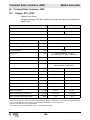
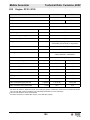
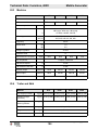
20 Technical Data: Cummins, 480V 184
20.1 Engine: G70 / G100 .................................................................................. 184
20.2 Engine: G130 / G150 ................................................................................ 185
20.3 Machine .................................................................................................... 186
20.4 Trailer and Skid ........................................................................................ 186
20.5 Dimensions ............................................................................................... 187
21 Technical Data: Cummins, 600V 188
21.1 Engine: G100 / G130 ................................................................................ 188
21.2 Machine .................................................................................................... 189
21.3 Trailer and Skid ........................................................................................ 189
21.4 Dimensions ............................................................................................... 190
22 Tire Safety Information 191
23 User’s Information for Transport Canada Fuel Tank 203
24 Emission Control Systems Information and Warranty—Diesel 206
24.1 Emission Control System Background Information .................................. 206
24.2 Limited Defect Warranty for Exhaust Emission Control System ............... 207

Table of Contents
Mobile Generator
wc_bo5100027027_07TOC.fm
14
24.3 Limited Defect Warranty for Wacker Neuson Emission Control
Systems .................................................................................................... 207
25 General Machine Schematics 211
25.1 Fuses ........................................................................................................ 211
25.2 Trailer Wiring ............................................................................................ 212
25.3 Trailer Wiring Components ....................................................................... 213
26 Schematics—Machines with Basler Controller 214
26.1 AC Schematic: G70 / G100 / G130 / G150, 480V .................................... 214
26.2 AC Schematic Components: G70 / G100 / G130 / G150 ......................... 215
26.3 DC Schematic: G70 / G100 / G130 / G150 .............................................. 216
26.4 DC Schematic Components: G70 / G100 / G130 / G150 ......................... 217
26.5 Electrical Schematic Section A ................................................................. 218
26.6 Electrical Schematic Components ............................................................ 219
26.7 Electrical Schematic Section B ................................................................. 220
26.8 Electrical Schematic Components ............................................................ 221
26.9 Electrical Schematic Section C ................................................................ 222
26.10 Electrical Schematic Components ............................................................ 223
26.11 Cummins Engine Relays and Fuses ........................................................ 224
26.12 Cummins Engine Relays and Fuses ........................................................ 225
27 Schematics—Machines with Deep Sea Controller 226
27.1 AC Schematic: G70 / G100 / G130 / G150, 480V .................................... 226
27.2 AC Schematic Components: G70 / G100 / G130 / G150 ......................... 227
27.3 AC Schematic: G100 / G130, 600V .......................................................... 228
27.4 Electrical Schematic Components: G100 / G130, 600V ........................... 229
27.5 DC Schematic: G70 / G100 / G130 / G150 (1 of 2) .................................. 230
27.6 DC Schematic Components: G70 / G100 / G130 / G150 (1 of 2) ............ 231
27.7 DC Schematic: G70 / G100 / G130 / G150 (2 of 2) .................................. 232
27.8 DC Schematic Components: G70 / G100 / G130 / G150 (2 of 2) ............ 233

wc_tx003567gb_FM10.fm
15
Mobile Generator Safety Information
1 Safety Information
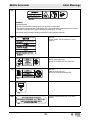
1.1 Signal Words Used in this Manual
This manual contains DANGER, WARNING, CAUTION, NOTICE, and NOTE
signal words which must be followed to reduce the possibility of personal injury,
damage to the equipment, or improper service.
NOTICE: Used without the safety alert symbol, NOTICE indicates a situation
which, if not avoided, could result in property damage.
Note: A Note contains additional information important to a procedure.
This is the safety alert symbol. It is used to alert you to potential personal hazards.
► Obey all safety messages that follow this symbol.
DANGER
DANGER indicates a hazardous situation which, if not avoided, will result in death
or serious injury.
► To avoid death or serious injury from this type of hazard, obey all safety
messages that follow this signal word.
WARNING
WARNING indicates a hazardous situation which, if not avoided, could result in
death or serious injury.
► To avoid possible death or serious injury from this type of hazard, obey all safety
messages that follow this signal word.
CAUTION
CAUTION indicates a hazardous situation which, if not avoided, could result in
minor or moderate injury.
► To avoid possible minor or moderate injury from this type of hazard, obey all
safety messages that follow this signal word.

wc_tx003567gb_FM10.fm
16
Safety Information Mobile Generator
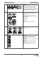
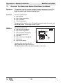
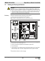
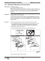
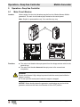
1.2 Machine Description and Intended Use
Machine
description
This machine is a mobile electric power source. The Wacker Neuson Mobile
Generator consists of a trailer-mounted cabinet containing an electric alternator, a
fuel tank, and a diesel engine. A control panel, receptacles, and connection lugs
are provided on the side of the cabinet. As the engine runs, the generator converts
mechanical energy into electric power. The operator connects loads to the electric
power receptacles and connection lugs.
Intended use
This machine is intended for the purpose of supplying electrical power to
connected loads. Refer to the product specifications for the output voltage and
frequency of this generator, and for the maximum output power limit of this
generator.
This machine has been designed and built strictly for the intended use described
above. Using the machine for any other purpose could permanently damage the
machine or seriously injure the operator or other persons in the area. Machine
damage caused by misuse is not covered under warranty.
The following are some examples of misuse:
■ Connecting a load that has voltage and frequency requirements that are
incompatible with the generator output
■ Overloading the generator with a load that draws excessive power during either
continuous running or start-up
■ Operating the generator in a manner that is inconsistent with all federal, state
and local codes and regulations
■ Using the machine as a ladder, support, or work surface
■ Using the machine to carry or transport passengers or equipment
■ Using the machine to tow other machines
■ Operating the machine outside of factory specifications
■ Operating the machine in a manner inconsistent with all warnings found on the
machine and in the Operator’s Manual
This machine has been designed and built in accordance with the latest global
safety standards. It has been carefully engineered to eliminate hazards as far as
practicable and to increase operator safety through protective guards and labeling.
However, some risks may remain even after protective measures have been taken.
They are called residual risks. On this machine, they may include exposure to:
■ Heat, noise, exhaust, and carbon monoxide from the engine
■ Fire hazards from improper refueling techniques
■ Fuel and its fumes
■ Electric shock and arc flash
■ Personal injury from improper lifting the trailer tongue
■ Typical hazards related to towing a trailer on roads and highways
To protect yourself and others, make sure you thoroughly read and understand the
safety information presented in this manual before operating the machine.

wc_tx003567gb_FM10.fm
17
Mobile Generator Safety Information
1.3 Safety Guidelines for Operating the Machine
Operator
training
Before operating the machine:
■ Read and understand the operating instructions contained in all manuals
delivered with the machine.
■ Familiarize yourself with the location and proper use of all controls and safety
devices.
■ Contact Wacker Neuson for additional training if necessary.
When operating this machine:
■ Do not allow improperly trained people to operate the machine. People
operating the machine must be familiar with the potential risks and hazards
associated with it.
Operator
qualifications
Only trained personnel are permitted to start, operate, and shut down the machine.
They also must meet the following qualifications:
■ Have received instruction on how to properly use the machine
■ Are familiar with required safety devices
The machine must not be accessed or operated by:
■Children
■ People impaired by alcohol, drugs, or prescription drugs
Application
area
Be aware of the application area.
■ Keep unauthorized personnel, children, and pets away from the machine.
■ Remain aware of changing positions and the movement of other equipment and
personnel in the application area/job site.
■ Identify whether special hazards exist in the application area, such as toxic
gases or unstable ground conditions, and take appropriate action to eliminate
the special hazards before using the machine.
■ Do not operate the machine in areas that contain flammable objects, fuels, or
products that produce flammable vapors.
Safety
devices,
controls, and
attachments
Only operate the machine when:
■ All safety devices and guards are in place and in working order.
■ All controls operate correctly.
■ The machine is set up correctly according to the instructions in the Operator’s
Manual.
■ The machine is clean.
■ The machine’s labels are legible.
To ensure safe operation of the machine:
■ Do not operate the machine if any safety devices or guards are missing or
inoperative.
■ Do not modify or defeat the safety devices.
■ Only use accessories or attachments that are approved by Wacker Neuson.

wc_tx003567gb_FM10.fm
18
Safety Information Mobile Generator
Safe
operating
practices
When operating this machine:
■ Remain aware of the machine’s moving parts. Keep hands, feet, and loose
clothing away from the machine’s moving parts.
■ Do not operate a machine in need of repair.
■ Do not consume the operating fluids used in this machine. Depending on your
machine model, these operating fluids may include water, wetting agents, fuel
(gasoline, diesel, kerosene, propane, or natural gas), oil, coolant, hydraulic oil,
heat transfer fluid (propylene glycol with additives), battery acid, or grease.
Personal
protective
equipment
(PPE)
Wear the following personal protective equipment (PPE) while operating this
machine:
■ Close-fitting work clothes that do not hinder movement
■ Safety glasses with side shields
■ Hearing protection
■ Safety-toed footwear
After use
■ Stop the engine when the machine is not being operated.
■ Close the fuel valve on engines equipped with one when the machine is not
being operated.
■ Ensure that the machine will not tip over, roll, slide, or fall when not being
operated.
■ Store the machine properly when it is not being used. The machine should be
stored in a clean location out of the reach of children.
1.4 Service Safety
Service
training
Before servicing or maintaining the machine:
■ Read and understand the instructions contained in all manuals delivered with
the machine.
■ Familiarize yourself with the location and proper use of all controls and
protective devices.
■ Only trained personnel shall troubleshoot or repair problems occurring with the
machine.
■ Contact Wacker Neuson for additional training if necessary.
When servicing or maintaining this machine:
■ Do not allow untrained or improperly trained people to service or maintain the
machine. Personnel servicing or maintaining the machine must be familiar with
the associated potential risks and hazards.
Precautions
When servicing or maintaining the machine:
■ Read and understand the service procedures before performing any service to
the machine.
■ All adjustments and repairs must be completed before operating the machine.
Do not operate the machine with a known problem or deficiency.
■ All repairs and adjustments shall be completed by a qualified technician.
■ Turn off the machine before performing maintenance or making repairs.

wc_tx003567gb_FM10.fm
19
Mobile Generator Safety Information
■ Remain aware of the machine’s moving parts. Keep hands, feet, and loose
clothing away from the machine’s moving parts.
■ Reinstall the safety devices and guards after repair and maintenance
procedures are complete.
Machine
modifications
When servicing or maintaining the machine:
■ Use only accessories/attachments that are approved by Wacker Neuson.
■ Do not defeat safety devices.
■ Do not modify the machine without the express written approval of Wacker
Neuson.
Replacing
parts and
labels
■ Replace worn or damaged components.
■ Replace all missing and hard-to-read labels.
■ When replacing electrical components, use components that are identical in
rating and performance to the original components.
■ When replacement parts are required for this machine, use only Wacker
Neuson replacement parts or those parts equivalent to the original in all types of
specifications, such as physical dimensions, type, strength, and material.
Cleaning
When cleaning and servicing the machine:
■ Keep machine clean and free of debris such as leaves, paper, cartons, etc.
■ Keep labels legible.
■ Do not clean the machine while it is running.
■ Never use gasoline or other types of fuels or flammable solvents to clean the
machine. Fumes from fuels and solvents can become explosive.
Personal
protective
equipment
(PPE)
Wear the following personal protective equipment (PPE) while servicing or
maintaining this machine:
■ Close-fitting work clothes that do not hinder movement
■ Safety glasses with side shields
■ Hearing protection
■ Safety-toed footwear
In addition, before servicing or maintaining the machine:
■ Tie back long hair.
■ Remove all jewelry (including rings).
Electrical
service safety
■ Make sure clothing and shoes are dry, stand on a dry wooden platform or rubber
insulating mat, and use tools with insulated handles when servicing the
machine.
■ Do not allow water to accumulate around the base of the machine. If water is
present, move the machine and allow the machine to dry before servicing.
■ Do not pressure wash the control panel, generator end, or any other electrical
components when cleaning the machine.

wc_tx003567gb_FM10.fm
20
Safety Information Mobile Generator
Cooling
system safety
■ Do not attempt to open the radiator cap while the unit is running or before the
engine has cooled down. Severe burns may result!
■ Engine coolant is toxic to humans and animals. Clean up spills and dispose of
waste engine coolant in accordance with local environmental regulations.
1.5 Operator Safety while Using Internal Combustion Engines
Operating
safety
When running the engine:
■ Keep the area around the exhaust pipe free of flammable materials.
■ Check the fuel lines and the fuel tank for leaks and cracks before starting the
engine. Do not run the machine if fuel leaks are present or the fuel lines are
loose.
■ Do not smoke while operating the machine.
■ Do not run the engine near sparks or open flames.
■ Do not touch the engine or muffler while the engine is running or immediately
after it has been turned off.
■ Do not operate a machine when its fuel cap is loose or missing.
■ Do not start the engine if fuel has spilled or a fuel odor is present. Move the
machine away from the spill and wipe the machine dry before starting.
■ Do not use the machine in areas with risk of explosion or fire.
Refueling
safety
When refueling the engine:
■ Clean up any spilled fuel immediately.
■ Refill the fuel tank in a well-ventilated area.
■ Reinstall the fuel tank cap after refueling.
■ Use tools specifically meant for refueling (for example, a fuel hose or funnel).
■ Do not smoke.
■ Do not refuel a hot or running engine.
■ Do not refuel the engine near sparks or open flames.
WARNING
Internal combustion engines present special hazards during operation and fueling.
Failure to follow the warnings and safety standards could result in severe injury or
death.
► Read and follow the warning instructions in the engine owner’s manual and the
safety guidelines below.
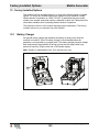
DANGER
Exhaust gas from the engine contains carbon monoxide, a deadly poison.
Exposure to carbon monoxide can kill you in minutes.
► NEVER operate the machine inside an enclosed area, such as a tunnel, unless
adequate ventilation is provided through items such as exhaust fans or hoses.
Page is loading ...
Page is loading ...
Page is loading ...
Page is loading ...
Page is loading ...
Page is loading ...
Page is loading ...
Page is loading ...
Page is loading ...
Page is loading ...
Page is loading ...
Page is loading ...
Page is loading ...
Page is loading ...
Page is loading ...
Page is loading ...
Page is loading ...
Page is loading ...
Page is loading ...
Page is loading ...
Page is loading ...
Page is loading ...
Page is loading ...
Page is loading ...
Page is loading ...
Page is loading ...
Page is loading ...
Page is loading ...
Page is loading ...
Page is loading ...
Page is loading ...
Page is loading ...
Page is loading ...
Page is loading ...
Page is loading ...
Page is loading ...
Page is loading ...
Page is loading ...
Page is loading ...
Page is loading ...
Page is loading ...
Page is loading ...
Page is loading ...
Page is loading ...
Page is loading ...
Page is loading ...
Page is loading ...
Page is loading ...
Page is loading ...
Page is loading ...
Page is loading ...
Page is loading ...
Page is loading ...
Page is loading ...
Page is loading ...
Page is loading ...
Page is loading ...
Page is loading ...
Page is loading ...
Page is loading ...
Page is loading ...
Page is loading ...
Page is loading ...
Page is loading ...
Page is loading ...
Page is loading ...
Page is loading ...
Page is loading ...
Page is loading ...
Page is loading ...
Page is loading ...
Page is loading ...
Page is loading ...
Page is loading ...
Page is loading ...
Page is loading ...
Page is loading ...
Page is loading ...
Page is loading ...
Page is loading ...
Page is loading ...
Page is loading ...
Page is loading ...
Page is loading ...
Page is loading ...
Page is loading ...
Page is loading ...
Page is loading ...
Page is loading ...
Page is loading ...
Page is loading ...
Page is loading ...
Page is loading ...
Page is loading ...
Page is loading ...
Page is loading ...
Page is loading ...
Page is loading ...
Page is loading ...
Page is loading ...
Page is loading ...
Page is loading ...
Page is loading ...
Page is loading ...
Page is loading ...
Page is loading ...
Page is loading ...
Page is loading ...
Page is loading ...
Page is loading ...
Page is loading ...
Page is loading ...
Page is loading ...
Page is loading ...
Page is loading ...
Page is loading ...
Page is loading ...
Page is loading ...
Page is loading ...
Page is loading ...
Page is loading ...
Page is loading ...
Page is loading ...
Page is loading ...
Page is loading ...
Page is loading ...
Page is loading ...
Page is loading ...
Page is loading ...
Page is loading ...
Page is loading ...
Page is loading ...
Page is loading ...
Page is loading ...
Page is loading ...
Page is loading ...
Page is loading ...
Page is loading ...
Page is loading ...
Page is loading ...
Page is loading ...
Page is loading ...
Page is loading ...
Page is loading ...
Page is loading ...
Page is loading ...
Page is loading ...
Page is loading ...
Page is loading ...
Page is loading ...
Page is loading ...
Page is loading ...
Page is loading ...
Page is loading ...
Page is loading ...
Page is loading ...
Page is loading ...
Page is loading ...
Page is loading ...
Page is loading ...
Page is loading ...
Page is loading ...
Page is loading ...
Page is loading ...
Page is loading ...
Page is loading ...
Page is loading ...
Page is loading ...
Page is loading ...
Page is loading ...
Page is loading ...
Page is loading ...
Page is loading ...
Page is loading ...
Page is loading ...
Page is loading ...
Page is loading ...
Page is loading ...
Page is loading ...
Page is loading ...
Page is loading ...
Page is loading ...
Page is loading ...
Page is loading ...
Page is loading ...
Page is loading ...
Page is loading ...
Page is loading ...
Page is loading ...
Page is loading ...
Page is loading ...
Page is loading ...
Page is loading ...
Page is loading ...
Page is loading ...
Page is loading ...
Page is loading ...
Page is loading ...
Page is loading ...
Page is loading ...
Page is loading ...
Page is loading ...
Page is loading ...
Page is loading ...
Page is loading ...
Page is loading ...
Page is loading ...
Page is loading ...
Page is loading ...
Page is loading ...
Page is loading ...
Page is loading ...
Page is loading ...
Page is loading ...
Page is loading ...
Page is loading ...
-
 1
1
-
 2
2
-
 3
3
-
 4
4
-
 5
5
-
 6
6
-
 7
7
-
 8
8
-
 9
9
-
 10
10
-
 11
11
-
 12
12
-
 13
13
-
 14
14
-
 15
15
-
 16
16
-
 17
17
-
 18
18
-
 19
19
-
 20
20
-
 21
21
-
 22
22
-
 23
23
-
 24
24
-
 25
25
-
 26
26
-
 27
27
-
 28
28
-
 29
29
-
 30
30
-
 31
31
-
 32
32
-
 33
33
-
 34
34
-
 35
35
-
 36
36
-
 37
37
-
 38
38
-
 39
39
-
 40
40
-
 41
41
-
 42
42
-
 43
43
-
 44
44
-
 45
45
-
 46
46
-
 47
47
-
 48
48
-
 49
49
-
 50
50
-
 51
51
-
 52
52
-
 53
53
-
 54
54
-
 55
55
-
 56
56
-
 57
57
-
 58
58
-
 59
59
-
 60
60
-
 61
61
-
 62
62
-
 63
63
-
 64
64
-
 65
65
-
 66
66
-
 67
67
-
 68
68
-
 69
69
-
 70
70
-
 71
71
-
 72
72
-
 73
73
-
 74
74
-
 75
75
-
 76
76
-
 77
77
-
 78
78
-
 79
79
-
 80
80
-
 81
81
-
 82
82
-
 83
83
-
 84
84
-
 85
85
-
 86
86
-
 87
87
-
 88
88
-
 89
89
-
 90
90
-
 91
91
-
 92
92
-
 93
93
-
 94
94
-
 95
95
-
 96
96
-
 97
97
-
 98
98
-
 99
99
-
 100
100
-
 101
101
-
 102
102
-
 103
103
-
 104
104
-
 105
105
-
 106
106
-
 107
107
-
 108
108
-
 109
109
-
 110
110
-
 111
111
-
 112
112
-
 113
113
-
 114
114
-
 115
115
-
 116
116
-
 117
117
-
 118
118
-
 119
119
-
 120
120
-
 121
121
-
 122
122
-
 123
123
-
 124
124
-
 125
125
-
 126
126
-
 127
127
-
 128
128
-
 129
129
-
 130
130
-
 131
131
-
 132
132
-
 133
133
-
 134
134
-
 135
135
-
 136
136
-
 137
137
-
 138
138
-
 139
139
-
 140
140
-
 141
141
-
 142
142
-
 143
143
-
 144
144
-
 145
145
-
 146
146
-
 147
147
-
 148
148
-
 149
149
-
 150
150
-
 151
151
-
 152
152
-
 153
153
-
 154
154
-
 155
155
-
 156
156
-
 157
157
-
 158
158
-
 159
159
-
 160
160
-
 161
161
-
 162
162
-
 163
163
-
 164
164
-
 165
165
-
 166
166
-
 167
167
-
 168
168
-
 169
169
-
 170
170
-
 171
171
-
 172
172
-
 173
173
-
 174
174
-
 175
175
-
 176
176
-
 177
177
-
 178
178
-
 179
179
-
 180
180
-
 181
181
-
 182
182
-
 183
183
-
 184
184
-
 185
185
-
 186
186
-
 187
187
-
 188
188
-
 189
189
-
 190
190
-
 191
191
-
 192
192
-
 193
193
-
 194
194
-
 195
195
-
 196
196
-
 197
197
-
 198
198
-
 199
199
-
 200
200
-
 201
201
-
 202
202
-
 203
203
-
 204
204
-
 205
205
-
 206
206
-
 207
207
-
 208
208
-
 209
209
-
 210
210
-
 211
211
-
 212
212
-
 213
213
-
 214
214
-
 215
215
-
 216
216
-
 217
217
-
 218
218
-
 219
219
-
 220
220
-
 221
221
-
 222
222
-
 223
223
-
 224
224
-
 225
225
-
 226
226
-
 227
227
-
 228
228
-
 229
229
-
 230
230
-
 231
231
-
 232
232
-
 233
233
-
 234
234
-
 235
235
-
 236
236


Wacker Neuson G130 User manual
- Category
- Power generators
- Type
- User manual
Ask a question and I''ll find the answer in the document
Finding information in a document is now easier with AI
Related papers
Other documents
-
WarmlyYours SCA-DUAL Controller Product information
-
MQ Power DCA300SSCU2_SSCU4i Operating instructions
-
CUMMINS QD 3200 HDZAA User manual
-
Legrand S120/277C-P Auxiliary Relay Pack Form C Installation guide
-
Toshiba 1600 User manual
-
-
-
Smartgen HEM4300 Owner's manual
-
-