Page is loading ...

AIR SYSTEMS INTERNATIONAL, INC.
829 Juniper Crescent, Chesapeake, Va, 23320
Telephone (757) 424-3967
Toll Free 1-800-866-8100
Fax No. (757) 424-5348
http://www.airsystems.com
e-mail: [email protected]
Manual No. TA3001
Rev. 4 April 2015
OPERATING MANUAL
MODELS:
TA-3
TA-3EA

2
OVERVIEW
SET-UP/OPERATION
MODEL: TA-3
The TA-3 is a portable 3 man breathing air compressor designed for use with pressure demand respirators when
used with a Grade-D ltration package. The system operates on 115 VAC / 60 Hz / 20 amp electrical service. The system
produces pressure up to 110 PSI (7.5 BAR) that is monitored by a built in pressure gauge. Adding a 30 or 60 minute air
cylinder, pressure reducing regulator, and an Auto Air Breather Box™ gives you a 3 man compressor with automatic back-
up air for IDLH operation.
Notes: The compressor should be connected to the ltration package with a minimum 1/2” I.D. breathing air hose.
Constant ow respirators cannot be used with this compressor system!
Always run, store, or ship the compressor in the horizontal position. Never stand the compressor upright as oil will
drain from the sump and cause damage to the compressor.
Check compressor oil level before each usage. If oil is low, add only Air Systems approved oil. Order P/N HP-268
USDA synthetic lubricant. Do not overll!
GRADE-D FILTRATION
1/2” I.D. BREATHING
AIR HOSE
RESPIRATOR HOSE
115 VAC POWER CORD
STEP 1)
Connect compressor to the Grade-D ltration unit using a 1/2” I.D. hose.
STEP 3)
Turn compressor on and note the gauge pressure. Pressure should reach 110 PSI (7.5 BAR).
STEP 4)
Attach hose(s) and respirator(s) to ltration unit. Up to 3 respirators can be used with this compressor. Never leave an
open (unused) respirator attached to the system as output pressure will not be maintained.
STEP 5)
Adjust the pressure regulator on the ltration unit to the required output pressure of the pressure demand respirator(s).
Review manual on the Grade-D ltration unit and carbon monoxide monitor for details on operation, service, and calibra-
tion before commencing work.
STEP 2)
Plug compressor power cord into a 115 VAC receptacle with a dedicated 20 amp service.
Note: If an extension cord is to be used be rated for a minimum 20 amp service (12 AWG).

3
SET-UP/OPERATION
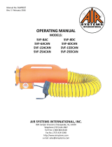
MODEL: TA-3EA
STEP 1)
Connect compressor to the primary air inlet on the Grade-D ltration unit using a 1/2” I.D. hose.
STEP 5)
Turn compressor on and note the gauge pressure. Pressure should reach 110 PSI (7.5 BAR).
STEP 6)
Attach hose(s) and respirator(s) to ltration unit. Up to 3 respirators can be used with this compressor. Never leave an
open (unused) respirator attached to the system as output pressure will not be maintained.
STEP 7)
Adjust the pressure regulator on the ltration unit to the required output pressure of the pressure demand respirator(s).
Review manual on the Grade-D ltration unit and carbon monoxide monitor for details on operation, service, and calibra-
tion before commencing work.
STEP 4)
Plug compressor power cord into a 115 VAC receptacle with a dedicated 20 amp service.
Note: If an extension cord is to be used be rated for a minimum 20 amp service (12 AWG).
STEP 2)
Connect back-up air regulator to back-up air inlet on the Grade D ltration unit using a 3/8” I.D. hose.
STEP 3)
Open back-up air cylinder valve and adjust pressure regulator to the required pressure of the respirator(s) being used.
GRADE-D FILTRATION
1/2” I.D. BREATHING
AIR HOSE CONNECTED
TO PRIMARY AIR INLET
2/8” I.D. BREATHING
AIR HOSE CONNECTED
TO BACK-UP AIR INLET
RESPIRATOR HOSE
115 VAC POWER CORD
BACK-UP AIR CYLINDER
PRESSURE REGULATOR

4
OIL CHANGE PROCEDURE
OIL COOLER
FILLER PLUG (P/N COMPA040)
FILLER PLUG (P/N COMPA040)
WASHER (P/N COMPA043)
SIGHT GLASS
FILL PLUG (P/N COMPA042)
Blow dust off of oil cooler periodically to prevent over-heating.
STEP 1)
View pressure gauge to insure there is no pressure in compressor body.
STEP 2)
Remove ller plug/dipstick and gasket. (replace gasket if necessary)
STEP 3)
Position a suitable container underneath compressor and remove drain plug and gasket. (replace gasket if necessary)
STEP 4)
When oil is nished draining, reinstall the drain plug and gasket.
STEP 6)
Reinstall the ller plug/dipstick and gasket. Tighten to approximately 25Nm (18.5 ft./lbs.)
STEP 7)
Run compressor for approximately 10 seconds, turn off, recheck oil level, and add if necessary.
STEP 5)
Fill compressor with factory approved oil. Use Air Systems part no. HP-268 (approximately .8 liters). Oil should reach the
bottom threads of the ller plug/dipstick or just to the top of the sight glass. DO NOT OVERFILL!

5
REPLACEMENT OF AIR INTAKE FILTER
REPLACEMENT OF OIL SEPARATOR ELEMENT
STEP 1)
Remove the outlet tting from the compressor.
STEP 2)
Remove the black plastic cowl from the air end by pulling rmly.
STEP 3)
Remove the foam air lter and clean or replace. If lter is in good condition it can be cleaned with a mild detergent and
water.
STEP 4)
With lter removed, clean inside of plastic cowl and separator casing.
STEP 5)
There are 2 styles of air lters used on these compressors. A donut style lter that slides over the air end and is not held
in place by retaining clips (new style) and a strip lter that is held in place by retaining clips (old style). If you receive the
donut style lter and you have the retaining clips on your air end, simply cut the donut lter so it will wrap around the sep-
arator casing and the ends of the lter will be held in place by the retaining clips.
PLASTIC COWL
AIR INTAKE FILTER
SEPARATOR CASING
RETAINING CLIP
STEP 1)
Remove retaining screws (A).
STEP 2)
Gently tap the end cover (B) until it is clear of the
separator casing.
STEP 3)
Unscrew the oil separator element (C) and discard.
STEP 4)
Install a new separator element (P/N COMPA022).
Ensure that the o-ring (E) is in place. Do not over-
tighten.
STEP 5)
Ret end cover (B). Ensure cover is positioned
correctly and bolt holes are in line. Be careful not to
damage o-ring (D) when retting.
STEP 6)
Ret cap screws (A) and tighten between 4-6.8 Nm
(3-5 ft./lbs.)

6
MAINTENANCE SCHEDULE
ORDERING INFORMATION
WARRANTY DISCLAIMER
Air Systems’ manufactured equipment is warranted to the original user against defects in workmanship or materials under
normal use for one year from the date of purchase. Any part which is determined by Air Systems to be defective in mate-
rial or workmanship will be, as the exclusive remedy, repaired or replaced at Air Systems’ option. This warranty does not
apply to electrical systems or electronic components. Electrical parts are warranted, to the original user, for 90 days from
the date of sale. During the warranty period, electrical components will be repaired or replaced at Air Systems’ option.
NO OTHER WARRANTY, EXPRESSED OR IMPLIED, AS TO DESCRIPTION, QUALITY, MERCHANTABILITY, FIT-
NESS FOR A PARTICULAR PURPOSE, OR ANY OTHER MATTER IS GIVEN BY AIR SYSTEMS IN CONNECTION
HEREWITH. UNDER NO CIRCUMSTANCES SHALL THE SELLER BE LIABLE FOR LOSS OF PROFITS, ANY OTHER
DIRECT OR INDIRECT COSTS, EXPENSES, LOSSES, OR DAMAGES ARISING OUT OF DEFECTS IN, OR FAILURE
OF THE PRODUCT OR ANY PART THEREOF.
The purchaser shall be solely responsible for compliance with all applicable Federal, State and Local OSHA and/or MSHA
requirements. Although Air Systems International believes that its products, if operated and maintained as shipped from
the factory and in accordance with our “operations manual”, conform to OSHA and/or MSHA requirements, there are no
implied or expressed warranties of such compliance extending beyond the limited warranty described herein. Product
designs and speci cations are subject to change without notice. Rev. 2, 12/98
Air leaks are not covered under warranty except when they result from a defective system component, i.e. an on/off valve
or regulator or upon initial delivery due to poor workmanship. Air leaks due to poor delivery or damage will be covered un-
der delivery claims. Minor air leaks are part of routine service and maintenance and are the responsibility of the customer
just as are lters and oil changes.
DAILY
Check oil level
Drain air receiver tanks
EVERY 50 HOURS
Check oil level
Clean or replace air intake lter
Clean oil cooler
EVERY 500 HOURS
Clean oil cooler
Change oil
Change air intake lter
Change oil separator
ITEM NUMBER
HP-268-1
HP-268-5
COMPA021
COMPA022
COMPA023
COMPA028
COMPA041
COMPA043
DESCRIPTION
USDA Approved Oil - 1 gallon
USDA Approved Oil - 5 gallon
Intake Air Filter
Oil Separator
“O” Ring Oil Separator (Rear)
“O” Ring Oil Separator (Front)
Oil Fill Plug Gasket
Oil Drain Plug Gasket

REPLACEMENT PARTS
7
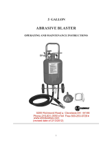
ITEM # DESCRIPTION PART #
1 OUTLET FITTING QDH5SL8M
2 125 PSI RELIEF VALVE VR4125BR
3 ON/OFF SWITCH ELSW021
4 10” PNEUMATIC TIRE HDWR108
5 POWER CORD ELCB008
6 BACK-UP AIR CONNECTION QDH3SL4MDC
7 CYLINDER PRESSURE GAUGE GA2075KB
8 REGULATOR REG004
9 CGA-347 STEM HPBR049
10 CGA-347 NUT HPBR050
11 150 PSI RELIEF VALVE VR4150BR
12 DISCHARGE PRESSURE GAUGE GA20160B

Printed in the U.S.A. ©Copyright Air Systems International, Inc. 2015 All Rights Reserved
AIR SYSTEMS INTERNATIONAL, INC.
829 Juniper Crescent, Chesapeake, Va, 23320
Telephone (757) 424-3967
Toll Free 1-800-866-8100
Fax No. (757) 424-5348
http://www.airsystems.com
e-mail: [email protected]
/