Novus N1500LC User manual

Type
User manual

Novus N1500LC is a digital panel meter for weighing systems with load cells, capable of accepting various electrical signals. It features a 6-digit LED display, memory for maximum and minimum values, hold, peak hold, tare, zero tare, and automatic zero functions. The device can be programmed via the front keypad. Optionally, it offers PV retransmission in 0-20 mA or 4-20 mA, RS485 Modbus RTU serial communication, and up to 4 alarm relays.

Novus N1500LC is a digital panel meter for weighing systems with load cells, capable of accepting various electrical signals. It features a 6-digit LED display, memory for maximum and minimum values, hold, peak hold, tare, zero tare, and automatic zero functions. The device can be programmed via the front keypad. Optionally, it offers PV retransmission in 0-20 mA or 4-20 mA, RS485 Modbus RTU serial communication, and up to 4 alarm relays.

NOVUS AUTOMATION 1/8
N15
00LC DIGITAL PANEL METER
D
IGITAL PANEL METERINSTRUCTIONS MANUAL – V2.3x K
SAFETY ALERTS
The symbols below are used on the equipment and throughout this
document to draw the user’s attention to important operational and
safety information.
CAUTION:
Read this manual carefully prior to
installation and operation of the
unit.
CAUTION OR DANGER:
Electric shock hazard
All safety related instructions that appear in the manual must be
observed to ensure personal safety and to prevent damage to either
the instrument or the system. If the device is used in a manner not
specified in this manual, its safety features may be impaired.
INTRODUCTION
N1500LC is a digital panel meter designed for weighing system with
load cells. It accepts a wide variety of electrical signals. It has a
display with 6-digit LED display for the measured value and device
parameters.
The whole device configuration is done through the keyboard without
any change in the circuit. Thus, the selection of input type and the
type of alarms action, besides other special functions, are all
accessed and programmed through the front keypad.
The main features of the basic version are as follows:
Input: 4-20 mA, 0-20 mA, 0-50 mV, 0-20 mV, and -20 to 20 mV
Increasing or decreasing display
10 Vdc (or 5 Vdc) power supply for load cells
Memory for maximum and minimum values
Hold, Peak Hold, Tare, Zero Tare and Automatic Zero functions
Digital input
Optionally, it can have:
Process Variable (PV) retransmission in 0-20 mA or 4-20 mA
RS485 Modbus RTU serial communication
3rd and 4th alarm relays
The front panel is shown below:
Figure 1 Identification of the elements of the front panel
Display: Displays the value of the measured variable (PV) and the
mnemonics of the device programming parameters.
A1, A2, A3, and A4: Display active alarms.
Rx and Tx: Display RS485 communication line is active.
P key: Key used to access different displays with the
programmable parameters of the device.
BACK key: Key used to go back to the previous parameter
displayed in the menu display.
INCREMENTS/ZERO key and DECREMENTS/ZERO
key: Keys used to change the parameter values. They are
also used to display maximum and minimum values stored
in memory.
Key Special function: This special function key is used for
programmed functions as explained in the SPECIAL
FUNCTION KEY AND DIGITAL INPUT section of this
manual.
PROCESS VARIABLE INPUT PV
The type of input to be used by the digital panel meter must be set
via keyboard, among types established in Table 1.
All input types available are factory calibrated and require no further
adjustment, except the definition of range of indication.
TYPE CODE MEASUREMENT RANGE
Non-linear 4-20 mA
c.4-20
Programmable indication range.
Three maximum range options:
-31000 to +31000
0 to +60000
0 to +120000 (only even values)
Non-linear signals will be
linearized according to the
programmed linearization.
Non-linear 0-20 mA
c.0-20
Linear 4-20 mA
4-20 a
Linear 0-20 mA
0-20 a
Non-linear 0-50 mV
c. 50
Non
-linear -20 to 20 mV
c. -20
Non-linear 0-20 mV
C. 20
Linear 0 50 mV
50
Linear -20 to 20 mV
-20.20
Linear 0-20 mV
20
Table 1 Input types accepted by the digital panel meter
N1500LC Digital Panel Meter
NOVUS AUTOMATION 2/8
ALARMS
The digital panel meter has 2 alarm outputs in the basic version and
up to 4 alarms outputs optionally.
Each alarm has a Warning Light in the front panel that shows when
it was activated.
ALARM FUNCTIONS
The alarms can be set to operate in seven different modes. These
modes are shown in Table 2 and described below.
The alarm can also be set as disabled.
OPEN SENSOR – IERR
The alarm is triggered whenever the sensor breaks or is badly
connected or broken.
LOW ALARMLO
Triggered whenever the measured value is below the alarm
Setpoint.
HIGH ALARMKI
Triggered whenever the measured value is above the alarm
Setpoint.
DIFFERENTIAL LOWDIF.LO
Triggered whenever the measured value is below the point set by:
(ALrEF - Deviation)
DIFFERENTIAL HIGH DIF.KI
Triggered whenever the measured value is above the point set by:
(ALrEF + Deviation)
DIFFERENTIAL (OR BAND) OUT OF RANGE DIF.OU
For Differential alarm, it is necessary to define two parameters:
Differential alarm reference value (ALrEF) and Alarm differential
Setpoint (Deviation).
The Differential out of range alarm occurs when the measured value
is outside the range defined by:
(ALrEF - Deviation) and (ALrEF + Deviation)
DIFFERENTIAL (OR BAND) WITHIN RANGE DIF.IN
Same as previous but acting within the range defined above.
TYPE PROMPT ACTION
Disabled
Off
Alarm disabled.
Open sensor (input
Error)
ierr
Alarm will go ON if the sensor breaks.
High alarm
(Low)
Lo
Alarm SP
PV
High alarm
(High)
Ki
PV
Differential low
(Differential Low)
Dif.lo
PV
ALreF
ALreF - Deviation
Differential high
(Differential High)
Dif.ki
PV
ALrEF + Deviation
ALrEF
Differential out of
range
(Differential Output)
Dif.OU
PV
ALrEF + Deviation
ALrEF
ALrEF - Deviation
Differential within
range
(Differential Input)
Dif.IN
PV
ALrEF + Deviation
ALrEF
ALrEF - Deviation
Table 2 Alarm basic functions
ALARM TIMER
N1500LC allows programming of the Time Setting of Alarms, being
able to set delays in alarm condition; send a single pulse at the time
of trigger; or allow the generation of sequential pulses.
Table 3 shows these advanced functions. Times T1 and T2 can be
programmed from 0 to 6500 seconds and are defined when setting
up the device. For alarms with no time delays, set T1 and T2 with
value 0 (zero).
The warning LEDs associated with the alarm always light up when
the alarm condition occurs, regardless of the status of the output
relay, which may be de-energized momentarily due to a time delay.
ADVANCED
FUNCTION
T1 T2 ACTION
Normal
Operation
0
0
Alarm Event
Alarm
Output
Delayed
0
1 to 6500 s
Alarm Event
Alarm
Output
T2
Pulse
1 to 6500
s
0
Alarm Event
Alarm
Output
T1
Oscillator
1 to 6500
s
1 to 6500 s
Alarm Event
Alarm
Output
T1
T2
T1
Table 3 Timer alarm functions
INITIAL BLOCK ALARM
The Initial Blocking option inhibits the alarm from being recognized
if an alarm condition is present when the controller is first energized.
The alarm will be triggered only after the occurrence of a non-alarm
condition followed by a new occurrence for the alarm.
The initial blocking is disabled for the Open Sensor alarm function.
SPECIAL FUNCTIONS
SPECIAL FUNCTION KEY AND DIGITAL INPUT
The key (special function key) as well as the Digital Input may
be assigned different functions that will be chosen during the setup.
The possible functions are:
ZEROZERO FUNCTION
Available only for the key. It resets the scale.
This function is used to eliminate the influence of interference or
small deviations in the zero of a scale. Reset is only accomplished if
the value shown in the scale is within 2 % of the end of scale.
Zero is not lost if the scale is turned off.
Note: This function can be performed automatically using the
parameters En A.z and A.Z.rAn.
LODISPLAYS MINIMUM
Set the key to, at the first touch, displays the minimum (Low)
value the digital panel meter measured since the last reset. On the
second touch, to show the maximum (High) measured by the digital
panel meter since the last reset. On the third touch, the device returns
to normal display.
Press the button for more than 5 seconds to reset. This way, the
minimum and maximum values will be erased, starting a new cycle.
XIDISPLAYS MAXIMUM
Displays the maximum (High) value the digital panel meter
measured since the last reset.
N1500LC Digital Panel Meter
NOVUS AUTOMATION 3/8
PKOLDMAXIMUM VALUE
The digital panel meter will automatically work in the Peak Hold
mode whenever the key or the digital input are programmed as
PkoLd.
This operation mode makes that the digital panel meter always
shows the maximum value measured, since the last time the
key or the Digital Input were pressed.
Each activation of the key or digital input triggers a new Peak
Hold cycle, resetting the reading of the display to the current value of
the measure.
RST CLEARS MAXIMUM AND MINIMUM
If configured with rSt, each activation of the key or digital input
clear the memory for a new cycle of maximum and minimum values.
KOLDFREEZE MEASURED VALUE
The Hold function freezes the measured value showed in the
display. Each time the key or the Digital Input is selected, there
is a change from Hold to normal mode.
Whenever the digital panel meter is in the Hold mode, the message
koLd will be displayed so that the operator will be aware that the
value displayed is the frozen value and not the current reading.
TARETARE FUNCTION
It is available only in the digital input configuration or through the
key.
It changes indication to zero (0000.0), regardless of the value applied
to the input. It is used to eliminate indications of defined values. To
eliminate the tare, you must press the key.
AND KEYS
The same Tare function available for the Digital Input can be quickly
applied by using the key, which does not need to be set up. The
key is used to eliminate the tare applied.
The digital panel meter accepts successive tares, provided that the
input signal (gross weight) does not exceed the end of scale.
PROCESS VARIABLE RETRANSMISSION
As an option, the digital panel meter can be supplied with an isolated
0-20 mA or 4-20 mA analog output for Process Variable (PV)
retransmission. Available at terminals 29 and 30 of the rear panel of
the device.
When this option is available, the retransmission is always enabled
and does not require any intervention.
The PV values that define the scale of the 0 mA / 4 mA to 20 mA
retransmission can be programmed in the high and low output
limits (0v.lol and 0v.kol) at the Configuration Cycle. These limits
can be defined freely, and you can make a retransmission with
increasing or decreasing behavior toward to the indicated value.
For a voltage output signal, an external shunt (calibrated resistor)
should be installed at the analog output terminals.
LOAD CELL POWER SUPPLY (AUXILIARY P. S.)
The digital panel meter provides a voltage power supply of 10 Vdc to
excite field transmitters with 35 mA current capacity.
Available at the back panel terminals 16 and 17.
CUSTOMIZED LINEARIZATION
The digital panel meter has five types of input for non-linear signals:
c.4-20, c.0-20, c.50, c.-20 and c.20
For using these signals, is necessary to adopt the Custom
Linearization option. This feature combines the input signal to 30
user-defined line segments; setting two points for each segment, a
start and end and the respective display values. Thus, the indication
will have a non-linear behavior set by the input signal.
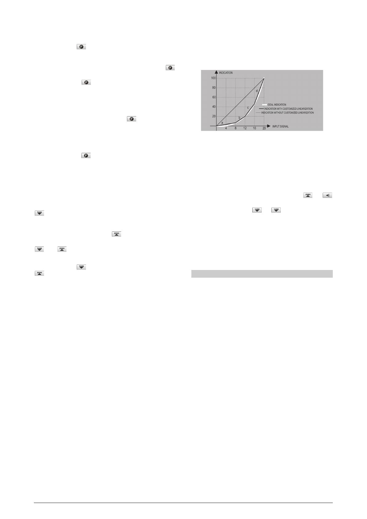
The following figure shows an input signal associated with four-line
segments (a, b, c, and d), causing that the resulting indication can be
approximated to the ideal value (characteristic curve). The resulting
indication is as best as the best straight segments are chosen.
Figure 2 Custom linearization for a nonlinear signal
Note: The non-linear input signal shall have increasing pattern.
CONFIGURATION PROTECTION
As a safety measure, parameter changes can be prevented through
a key combination performed at each level. With this protection, the
parameters are still displayed but cannot be changed.
To protect any level, just go to the level and press the and
keys simultaneously for 3 seconds.
To unlock the level, press the and keys for 3 seconds.
The display will flash briefly to confirm locking or unlocking
level.
Inside the controller, the PROT key complements the protection
function. In the OFF position, you can do and undo the protection of
cycles. In the ON position, you cannot make changes. If there are
protections cycles, these cannot be removed; if there is not, they
cannot be promoted.
INSTALLATION
The digital panel meter is designed to be panel mounted. Remove the
two plastic fixing clamps from the instrument, insert the device into the
panel cut-out and slide firmly the fixing clamps from the rear against the
panel.
INSTALLATION RECOMMENDATIONS
The wires of the input signals must be installed separated from
the output wires and power. If possible, in grounded conduits.
The power supply for the instruments must be provided from an
exclusive power source.
In controlling and monitoring applications, possible
consequences of any system failure must be considered in
advance. The internal alarm relay does not warrant total
protection.
Use of RC FILTERS (47 R and 100 nF, serial) are highly
recommended when driving solenoids, contactor coils or other
inductive loads.
N1500LC Digital Panel Meter
NOVUS AUTOMATION 4/8
ELECTRICAL CONNECTIONS
The whole inner part can be removed without the need to make any
disconnection.
Figure 3 shows the connection arrangement at the rear panel of the
digital panel meter:
Figure 3 Back panel terminals
POWER CONNECTION
First check if the voltage required by the digital panel meter is
compatible with the voltage of instrument power supply. Provide
adequate protection devices.
Figure 4 Power Connection
INPUT SIGNAL CONNECTION
It is important that they are very well connected, the sensor wires
must be well fixed in the terminals of the rear panel.
Figure 5 Voltage
connection
Figure 6 Current
connection
LOAD CELL CONNECTION USING THE POWER SUPPLY
Figure 7 Load cell
DIGITAL INPUT (DIG IN)
To use the Digital Input, a switch must be connected to respective
terminals (dry contact), as shown in Figure 8:
Figure 8 Using the digital input
ANALOG OUTPUT (4-20 MA OUTPUT)
The analog output may be 0-20 mA or 4-20 mA, selected in the
configuration.
The output is available at terminals 29 and 30, as requested in the
purchase order.
OPERATION
For best results, this digital panel meter requires correct basic setting
of parameters or a definition for parameters displayed. It is necessary
to define, for example: Input type (0-20 mA, 4-20 mA, etc.), range
display, alarm set point, alarm function etc.
To make configuration easier, the parameters are divided in five
cycles (or groups):
CYCLE
ACCESS
1 Work
Free access
2 Alarms
Reserved access
3 Special functions
4 Input setting
5 Customized linearization
6 Calibration
7 Automatic calibration
Table 4 Parameters cycles
The work cycle has free access. All other cycles require a certain
combination of keystrokes to be accessed. The combination is:
and keys pressed simultaneously
Once within a cycle, just press to move to the subsequent
parameters of this cycle. At the end of each cycle the display will go
back to the work cycle.
At the desired parameter, just press the buttons or to
promote the desired changes. These changes are saved into
protected memory and given as valid when we move to the next
parameter.
After 25 seconds with no key pressed the digital panel meter will
return to the Measurement screen at work cycle.
Note: It is recommended to disable/suspend the control whenever it
is necessary to change the device settings.
PROGRAMMING THE DIGITAL PANEL METER
WORK CYCLE
This is the first cycle. At power up, the digital panel meter will display
the Process Variable (PV). The alarm triggering points are also
displayed at this cycle (alarm Setpoints).
To advance in this cycle, simply press key.
SCREEN PARAMETER DESCRIPTION
8.8.8.8.8.
Screen measures.
Shows the variable measured according to the limits
defined in the
in.LoL
and
in.kiL
screens.
Should any failure occur, the digital panel meter will
display an error message.
Al.ref
Differential alarm reference value.
This screen is shown only when there is an alarm
programmed with differential function.
This value is used as a reference for differential
alarms triggering.
Sp.al1
Sp.al2
Sp.al3
Sp.al4
Alarms SPs 1, 2, 3 and 4.
Defines the operation point of each alarm
programmed with
Lo
or
ki
functions.
For alarms programmed with differential functions,
the alarm SP value cannot be changed, and the
diF
message is displayed.
N1500LC Digital Panel Meter
NOVUS AUTOMATION 5/8
The value of differential SP (deviation) is defined in
the Alarms Cycle.
Note: The SP adjustment parameters are presented
only if the corresponding alarm function is
configured.
ALARM CYCLE
fV.al1
fV.al2
fV.al3
fV.al4
Alarm function
.
Defines the alarm functions: 1, 2, 3 or 4, configured
in ALARM FUNCTIONS section.
oFF
Alarm off
iErr
Broken or Shorted Sensor
Lo
Low value
ki
High value
Dif.lo
Differential low
Dif.ki
Differential high
Dif.OU
Differential outside the range
Dif.IN
Differential within range
Ky.al1
Ky.al2
Ky.al3
ky.al4
Alarm hysteresis.
Defines the difference between the value at which
the alarm is turned on and the value at which it is
turned off.
Bl.al1
Bl.al2
Bl.al3
bl.al4
Initial Blocking Function.
It makes possible to prevent alarms activation at the
process start when all the system is powered.
Al1t1
Al1t2
Al2t1
Al2t2
Al3t1
Al3t2
Al4t1
Al4t2
Alarm Timer Function.
Sreens that define time T1 and T2, in seconds,
shown in Table 3.
They allow to delay the alarm triggering, to activate
alarms momentarily or sequentially.
To disable timer function, just set zero for T1 and T2.
FUNCTION CYCLE
f.fvnc
key function.
Makes possible to define the key function.
Available functions:
oFF
Key not used
kold
Hold PV
RSt
Resets maximum and minimum values
PkoLd
Peak Hold
XI
Displays maximum
LO
Displays minimum
ZERO
Automatic zero
These functions are d
escribed in detail in the
SPECIAL FUNCTION KEY AND DIGITAL INPUT
section.
Dig.in
Digital input function.
Makes possible to define the digital input function.
Functions available are the same as the ones
available for the key, except for the Zero
function, replaced by the Tare function.
oFF
kold
rSt
PkoL
XI
LO
tare
These functions are described in detail in the
SPECIAL FUNCTION KEY AND DIGITAL INPUT
section.
filtr
Input digital filter.
Used to reduce the noise in the measured value.
Adjustable from 0 to 60. 0 means the filter is off and
60 means maximum filtering. The filter slows down
the response of the measured value.
ofset
Displayed offset.
Added value to the measured value to correct the
Offset. Expressed in the unit configured input type.
En A.z
Enables Auto Zero.
Enables the Auto Zero function of the indication. The
indication will turn to zero if the input value is within
the programmed range in
A.Zran
for 3 seconds.
Auto Zero occurs when the indication is relatively
stable. It is used to eliminate the influence of
interference or small deviations in the zero of a scale.
A.Z.rAn
Maximum level for zero.
Maximum level of the scale zero deviation, where
auto-zero is activated. This value can be programmed
up to 2 % of the end of scale.
Bavd
Communication Baud Rate.
Transmission Baud Rate
used in serial
communication (RS485) in bps and kbps.
1200, 2400, 4800, 9600, 19200,
38400, 57600,
115.2. (NONE parity) 1.2P, 2.4P, 4.8P, 9.6P, 19.2P,
38.4P, 57.6P and 115.2P (with EVEN parity).
Adres
Communication address.
A number that identifies the device in a
communication network.
CONFIGURATION CYCLE
In.typ
Input type.
Selects the input signal or s
ensor type to be
connected to the PV terminals.
Changing the input type causes all other parameters
related to PV and alarms to be changed as well.
This parameter shall be the first to be set.
Dp.pos
Decimal point position.
Determines the position of the decimal point in the
display.
scale
Parameter that defines the indication limits of the
inputs.
0
Configurable indication from 31000 to + 31000.
1
Configurable indication from 0 to + 60000.
2
Configurable indication from 0 to +120000,
showing only even values.
The PV values, SP Alarms and Offset also obey
these limits.
In.lol
Input low limit.
Determines the minimum limit for input signals. The
range created can be ascending or descending in
relation to the input signal behavior.
In.kil
Input high limit.
Determines the maximum limit for input signals. The
range created can be ascending or descending in
relation to the input signal behavior.
Ovt.ty
Analog output type
.
Allows selecting the signal type available on the
analog output: 0-20 mA or 4-20 mA.
N1500LC Digital Panel Meter
NOVUS AUTOMATION 6/8
ov.lol
Output Low Limit
Low limit for analog retransmission.
Determines the display value corresponding to an
electric current of 4 mA (or 0 mA).
0v.kil
Output High Limit
High limit for analog retransmission.
Defines the PV value that results in a 20 mA analog
output current.
Ovt.er
Output error
Error signaling for 4-20 mA output.
Configure the status of the analog output when an
error occurs in the retransmission (beginning or end
of the scale).
CUSTOMIZED LINEARIZATION CYCLE
Inp.01
Inp.30
Defines the extreme points of the customized
linearization.
Values must be in the input signal unit.
Ovt.01
Ovt.30
Defines the proportional indications in respect to
each segment of the customized linearization.
Values are in the intended indication unit.
CALIBRATION CYCLE
All input and output types are factory calibrated. We recommend not
making any calibration procedure. This cycle should only be
accessed by experienced personnel.
If this cycle is accidentally accessed, do not touch the or
keys. Go through all the screens until you return to Operating Cycle
(operation).
In..lo(
Zero input calibration.
It allows you to calibrate the offset of PV. You can
increment or decrement the desired value by
pressing the and
keys
.
In.ki(
Span input calibration.
Sets the PV gain.
Ov.lo(
Zero calibration for the analog output.
Value for the analog output Offset (0 or 4 mA).
Ov.Ki(
Analog output Span calibration
.
Value for gain calibration of the analog output (20 mA).
k.type
Hardware type.
Parameter to adjust the digital panel meter to the
type of available hardware.
Should not be changed
, except when a new
accessory is inserted or removed.
2 Alarms ............................................. Code 3
2 Alarms and 4-20 mA ..................... Code 19
2 Alarms and RS485 ........................ Code 35
2 Alarms and 4-20 mA and RS485 .. Code 51
4 Alarms ........................................... Code 15
4 Alarms and 4-20 mA ..................... Code 31
4 Alarms and RS485 ........................ Code 47
4 Alarms and 4-20 mA and RS485 .. Code 63
AUTOMATIC CALIBRATION CYCLE
Specific calibration for weighing systems, where the user himself
performs the calibration of their system, using two reference weights,
minimum and maximum, and setting their indication values.
To access this cycle, press and keep pressed and for 30
seconds.
A(all
Minimum weight automatic calibration.
This parameter defines the value to be displayed when
the minimum reference weight is applied.
See the PERFORMING AUTOMATIC CALIBRATION
section.
A(alk
Maximum weight automatic calibration.
This parameter defines the value to be displayed when
the maximum reference weight is applied.
See the PERFORMING AUTOMATIC CALIBRATION
section.
Table 5 shows the sequence of cycles and parameters presented in the display. There are parameters that must be defined for each alarm
available.
WORK CYCLE ALARM CYCLE FUNCTION CYCLE
CONFIGURATION
CYCLE
CUSTOMIZED
LINEARIZATION CYCLE
CALIBRATION
CYCLE
AUTOMATIC
CALIBRATION
CYCLE
8.8.8.8.8.
* Fv.al1
f.fvn(
In.typ
Inp.01 - inp.30
In.lo(
A(all
Al.ref
*
Ky.al1
Dig.in
Dp.pos
OVt.01
-
ovt.30
In.ki(
A(alk
* Sp.al1
* Bl.al1
Filtr
Scale
Ov.lo(
* Al.1t1
Ofset
In.lol
Ov.ki(
* Al.1t2
En a2
In.kil
k.type
A2 ran
OVT.TY
Bavd
ov.lol
Adres
Ov.kil
OVT.er
Table 5 Sequence of cycles and parameters displayed by the digital panel meter
* Parameters that require definition for each available alarm.
NOVUS AUTOMATION 7/8
CONFIGURATOR SOFTWARE
Available for free download from the NOVUS website, QuickTune
software is the ideal tool to configure the N1500. It also has
diagnostic tools.
To configure the device, simply follow the procedure below:
1. Download and install the software on the computer to be used.
2. Run QuickTune, set up communication and start device
recognition.
PROBLEMS WITH THE DIGITAL PANEL METER
Connection errors or improper configuration will result in
malfunctioning. A final review can avoid wasting time and losses.
Some error messages will help to identify possible problems.
MESSAGE
PROBLEM DESCRIPTION
VVVVV Measured value is above the value allowed for the
selected sensor or signal limit.
nnnnn
Measured value is below the value allowed for the
selected sensor or signal limit.
----- Open input. No signal.
Table 6 Error messages
Other error messages shown by the digital panel meter must be
reported to the manufacturer. Inform the serial number if this should
occur. The serial number can be viewed at the display by pressing
the key for about 3 seconds.
The software version of the device can be viewed at the time it is
powered.
When not properly configured, the device may show false error
messages, particularly those related to the input type selected.
SPECIAL RECOMMENDATIONS
Should the digital panel meter be repaired, some special handling
should be taken.
The device must be withdrawn from the housing and immediately
placed in an anti-static wrap; protected from excessive heat and
humidity.
INPUT CALIBRATION
When recalibration of some type of input is required, proceed as
described below.
You must use an appropriate framework for calibration, with
equipment capable to provide the proper electrical signals.
a) Set the digital panel meter for the input type to be calibrated
(See Table 1).
b) Program the desired upper and lower display limits (in.lol and
in.kil) with limits on the type of configured input (See Table
1).
c) Access the inLo( parameter and applied to input a signal
corresponding to a known value and slightly above of the lower
limit.
d) Set the indicated value using the and keys to adjust
the expected value for the applied signal.
e) Access the inki( parameter and applied to input a signal
corresponding to a known value and slightly below of the upper
limit.
f) Set the indicated value using the and keys to adjust
the expected value for the applied signal.
g) Exit the Calibration Cycle and verify that the calibration became
adequate. Repeat c to f until no new adjustment is necessary.
PERFORMING AUTOMATIC CALIBRATION
To perform automatic calibration, the system must already be
installed and configured with the input type and range already
defined.
a) Access the Auto Calibration Cycle and the A(all parameter.
b) Put on the load cell the minimum reference weight and wait to
stabilize.
c) Adjust the A(all parameter to display the desired value.
d) Press the key to save this value and advance to the
parameter A(alk parameter.
e) Put on the load cell the maximum reference weight and wait to
stabilize.
f) Adjust the parameter A(alk to display the desired value.
g) Press key to save this value and terminate the procedure.
At this time, the digital panel meter will show the weight on the
load cell.
SERIAL COMMUNICATION
The digital panel meter can be supplied with an asynchronous
RS485 digital communication interface for master-slave connection
to a host computer (master). The digital panel meter always works as
a slave.
Communication is always initiated by the master, which sends a
command to the slave address with which to communicate. The
addressed slave takes over the line and sends the requested reply.
The digital panel meter accepts broadcast commands (addressed to
all instruments of the network). In this type of command, the digital
panel meter does not send any response
N1500LC uses signals compatible with the RS485 standard allows 2-
wire connection with a master and up to 31 digital panel meters (and
can address up to 247) with bus topology.
Maximum connection distance: 1000 meters.
Digital panel meter off time: Maximum 2 ms after the last byte.
Communication signals are electrically isolated from the rest of the
device, with selectable Baud Rate between 1200, 2400, 4800, 9600,
19200, 38400, 57600, and 115600 bps.
Number of data bits: 8 with no parity or even parity.
Number of stop bits: 1
Response start time: Maximum 100 ms after receiving the
command.
Protocol: MODBUS (RTU)
Signals from the RS485 interface are:
D1
D D +
B Bidirectional data line. Terminal 25
D0
D -
A Inverted bidirectional data line. Terminal 26
C
Optional connection. Improves
communication performance. Terminal 27
GND
Table 7 RS485
In case the host computer does not have an RS485 interface
integrated, shall be used an external RS232 RS485 converter.
Two parameters must be configured to use the serial communication
interface: Communication Baud Rate (bavd parameter) and
Communication Address (adres parameter).
N1500LC Digital Panel Meter
NOVUS AUTOMATION 8/8
SPECIFICATIONS
DIMENSIONS: ............................................ 48 x 96 x 92 mm (1/8 DIN)
Approximate weight: ............................................................. 250 g
PANEL CUT-OUT: .................................... 45 x 93 mm (+0.5 -0.0 mm)
POWER: .................................... 100 to 240 Vac/dc (±10 %), 50/60 Hz
Optional 24 V: ..................... 12 to 24 Vcc / 24 Vca (-10 % / +20%)
Max. consumption: ............................................................. 7.5 VA
ENVIRONMENTAL CONDITIONS:
Operating temperature: ................................................ 5 to 50 °C
Maximum RH: ..................................................... 80 % up to 30 °C
For temperatures above 30 °C, decrease 3 % per °C
For indoor use; Installation category II, pollution degree 2;
altitude < 2000 m
INPUT ........... Voltage and Current; configurable according to Table 1
Internal resolution: ................................................ 128000 levels
Display resolution: .................................................. 62000 levels
Input sample rate: .................................. 15 samples per second
Accuracy: .............................................................. 0.2 % of span.
Input impedance: ............................................. 0-50 mV >10 M
................................. 0-20 mA, 4-20 mA: 15 (+2 Vdc @ 20 mA)
ANALOG OUTPUT: ........................ 0-20 mA or 4-20 mA, 550 max.
4000 levels, isolated, for control or retransmission of PV and SP
RELAY OUTPUT: ALM1 and ALM2: SPDT: 3 A / 240 Vac (3 A / 30 Vdc
Res.)
ALM3 and ALM4: SPST-NO: 1.5 A / 250 Vac (3 A / 30 Vdc Res.)
AUXILIARY VOLTAGE SUPPLY: .............. 5 or 10 Vdc, ±1 %, 35 mA
EMC: ................................. EN61326-1:1997 and EN61326-1/A1:1998
SAFETY: .......................... EN61010-1:1993 and EN61010-1/A2:1995
CONNECTIONS SUITABLE FOR TERMINAL TYPE FORK 6.3 MM
FRONT PANEL: ................................... IP65, polycarbonate UL94 V-2
HOUSING: .................................................. IP20, ABS + PC UL94 V-0
STARTS OPERATION: 3 seconds after power-up.
CERTIFICATIONS:
IDENTIFICATION
N1500LC - 4R - RT - 485 - 24V
A B C D E
A: Model N1500LC Version dedicated for load
cells
B: Relays outputs blank (2 relays) or 4R (4 relays)
C: Analog output RT (PV retransmission in mA) or
blank
D:Digital Communication 485 (RS485, Modbus protocol) or
blank
E: Power Supply blank (100-240 Vac/dc) or 24V (24
Vdc/ac)
WARRANTY
Warranty conditions are available on our website
www.novusautomation.com.br/warranty.
  • Page 1 1
  • Page 2 2
  • Page 3 3
  • Page 4 4
  • Page 5 5
  • Page 6 6
  • Page 7 7
  • Page 8 8

Novus N1500LC User manual

Type
User manual

Novus N1500LC is a digital panel meter for weighing systems with load cells, capable of accepting various electrical signals. It features a 6-digit LED display, memory for maximum and minimum values, hold, peak hold, tare, zero tare, and automatic zero functions. The device can be programmed via the front keypad. Optionally, it offers PV retransmission in 0-20 mA or 4-20 mA, RS485 Modbus RTU serial communication, and up to 4 alarm relays.

Ask a question and I''ll find the answer in the document

Finding information in a document is now easier with AI