DANGER! EXPLOSION HAZARD. WHEN THE
WELL TANK HAS BEEN IN SERVICE AND A
CHANGE TO A HIGHER PRE-CHARGE PRESSURE IS NECESSARY
DUE TO A REQUIRED CHANGE IN THE PRESSURE SWITCH SETTING,
FAILURE TO FOLLOW INSTRUCTIONS BELOW CAN CAUSE A
RUPTURE OR EXPLOSION, POSSIBLY CAUSING SERIOUS OR FATAL
PERSONAL INJURY, AND/OR PROPERTY DAMAGE.
• DO NOT ADJUST OR ADD PRESSURE IF THERE HAS BEEN A
LOSS OF AIR.
• DO NOT ADJUST THE PRE-CHARGE PRESSURE IF THERE IS
VISIBLE EXTERIOR CORROSION.
• DO NOT ADJUST THE PRE-CHARGE PRESSURE IF THERE
HAS BEEN A REDUCTION OF THE PUMP CYCLE TIME OR
THE PRE-CHARGE PRESSURE COMPARED TO ITS INITIAL
SETTING. THIS IS BECAUSE REDUCTION IN PUMP CYCLE TIME
CAN RESULT FROM LOSS OF TANK AIR PRESSURE WHICH IN
TURN CAN MEAN THERE MAY BE INTERNAL CORROSION AND
ANY RE-PRESSURIZATION OR ADDITIONAL PRESSURE COULD
RESULT IN RUPTURE OR EXPLOSION.
MAXIMUM WORKING PRESSURE. Every Titan is
tested to 125 psig, the maximum working pressure
for the Titan line. Should pressures exceed 125 psig, proper selection
and sizing of an ASME Well-X-Trol should be made.
RELIEF VALVE REQUIRED. A relief valve should
be installed which is set to open at excessive
pressures (100 psig or more). This will protect the Titan and other system
components should the pressure switch malfunction and fail to shut the
pump off. The relief valve should be installed at the connection of the
Titan to the system piping and have a discharge equal to the pump’s
capacity at 100 psig.
AS IN ALL PLUMBING PRODUCTS AND WATER
STORAGE VESSELS, BACTERIA CAN GROW IN
YOUR WELL TANK, ESPECIALLY DURING TIMES OF NON-USE.
CONSULT YOUR LOCAL PLUMBING OFFICIAL REGARDING ANY
STEPS YOU MAY WISH TO TAKE TO SAFELY DISINFECT YOUR
HOME’S PLUMBING SYSTEM.
A water test must be taken before installation of any
water treatment equipment.
DANGER! EXPLOSION HAZARD. IF YOU
ADJUST THE PRE-CHARGE PRESSURE OR ADD
PRESSURE TO A TANK THAT IS CORRODED OR DAMAGED OR
WITH DIMINISHED INTEGRITY, THE TANK CAN BURST OR EXPLODE,
POSSIBLY CAUSING SERIOUS OR FATAL PERSONAL INJURY AND/
OR PROPERTY DAMAGE.
• ONLY ADJUST THE PRE-CHARGE AS DESCRIBED IN THIS
MANUAL WHEN THE TANK IS NEW OR WHEN THE INTEGRITY OF
THE TANK AND LACK OF INTERNAL OR EXTERNAL CORROSION
IS CONFIRMED.
• ONLY LICENSED PROFESSIONALS SHOULD CHECK, ADJUST OR
RE-CHARGE THE PRE-CHARGE OF TANKS.
For your safety, the information in this manual must
be followed to minimize the risk of electric shock,
property damage or personal injury.
• Properly ground to conform with all governing codes and ordinances.
Do not install in direct sunlight. Excessive sun heat
may cause distortion or other damage to non-
metallic parts.
Use only lead-free solder and flux for all sweat-
solder connections, as required by state and
federal codes.
ELECTROCUTION AND EXPLOSION HAZARD.
Before work is performed on the tank, turn off the
power to the pump and release all water pressure in the tank and
pumping system.
PLEASE READ THE FOLLOWING INSTRUCTIONS CAREFULLY
IMPORTANT GENERAL SAFETY INFORMATION -
ADDITIONAL SPECIFIC SAFETY ALERTS APPEAR IN THE FOLLOWING INSTRUCTIONS.
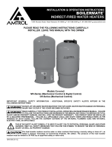
Air
Water
Pressure
Switch
Pump
Fixture Closed
Pressure
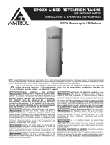
Air
Water
Pump
Fixture Open
Pressure
Switch Pressure
How a Well Tank Works
1. As the pump fills the tank with water, the air above the
diaphragm is compressed. This increases the pressure in the
tank and causes the pressure switch to turn off the pump.
2. When water is used, it is drawn from the tank and the pressure
inside the tank decreases. The reduced pressure starts the
pump and refills the tank.
The amount of water delivered between pump cycles is called drawdown. The larger the well tank, the greater the drawdown capacity,
the less the pump needs to run. This saves energy and money, and extends pump life. Larger tank sizes also increase the water storage
volume to provide more consistent water pressure.