GE PVWC924 Owner's Manual and Installation Instructions
- Category
- Cooker hoods
- Type
- Owner's Manual and Installation Instructions
This manual is also suitable for

Safety Instructions ................... 1, 2
Operating Instructions .................3, 4
Carbon Filter ............................3, 4
Grease Filter ...............................3
Halogen Light Bulbs ........................4
Care and Cleaning. . . . . . . . . . . . . . . . . . . . 5, 6
Charcoal Filter .............................5
Grease Filter ...............................5
Hood Lights ................................6
Stainless Steel Surfaces. . . . . . . . . . . . . . . . . . . . .6
Installation Instructions .............7–14
Troubleshooting Tips .................. 15
Consumer Support
Consumer Support .......................19
Product Registration ......................16
Warranty ................................18
Range Hoods
Hottes de cuisinière
Inscrivez ici les numéros de modèle et de série :
Nº de modèle _____________________________
Nº de série _______________________________
Ces numéros se trouvent sur une étiquette située
à l’arrière de la hotte, derrière les ltres à treillis
amovibles.
Owner’s Manual and
Installation Instructions
PVWC924
PVWC930
PVWS930
PVWG930
PVWT930
Sécurité ...........................20, 21
Utilisation .........................22, 23
Ampoules halogène ......................23
Filtre à charbon .......................22, 23
Filtre à graisses .......................22, 23
Entretien et nettoyage ..............24, 25
Filtre à charbon ..........................24
Filtre à graisses ..........................24
Lampes de la hotte ....................... 25
Surfaces en acier inoxydable .............25
Installation .......................26 à 33
Dépannage ........................... 34
Service à la clientèle
Enregistrement du produit ................16
Garantie .................................36
Service à la clientèle ......................37
Manuel de l’utilisateur et
instructions d’installation
PVWC924
PVWC930
PVWS930
PVWG930
PVWT930
Write the model and serial numbers here:
Model # _______________________________
Serial # _______________________________
You can nd them on a label on the back wall
of the hood, behind the removable mesh lters.
350A4502P736 11-12 ATS
www.GEAppliances.ca www.electromenagersge.ca

1
IMPORTANT SAFETY INSTRUCTIONS.
FOR RESIDENTIAL USE ONLY.
READ AND SAVE THESE INSTRUCTIONS.
PLEASE READ ENTIRE INSTRUCTIONS BEFORE PROCEEDING.
IMPORTANT: Save these Instructions for the Local Electrical Inspectors use.
INSTALLER: Please leave these Instructions with this unit for the owner.
OWNER: Please retain these instructions for future reference.
Take care when using cleaning agents or detergents.
Suitable for use in household cooking area.
WARNING - To reduce the risk of re or electric shock, do not use this fan with
any Solid-State Speed Control Device.
CAUTION - To reduce risk of re and to properly exhaust air, be sure to duct
air outside – Do not vent exhaust air into spaces within walls or ceilings or into
attics, crawl spaces, or garages.
CAUTION - For general ventilating use only. Do not use to exhaust hazardous or
explosive materials and vapors.
CAUTION - To avoid motor bearing damage and noisy and/or unbalanced
impellers, keep drywall spray, construction dust, etc. off power unit.
CAUTION - Please read specication label on product for further information and
requirements.
WARNING – TO REDUCE THE RISK OF FIRE, ELECTRIC SHOCK, OR INJURY TO
PERSONS, OBSERVE THE FOLLOWING:
A. Use this unit only in the manner intended by the manufacturer. If you have
questions, contact the manufacturer.
B. Before servicing or cleaning unit, switch power off at service panel and lock
the service disconnecting means to prevent power from being switched on
accidentally. When the service disconnecting means cannot be locked, securely
fasten a prominent warning device, such as a tag, to the service panel.
WARNING - TO REDUCE THE RISK OF A RANGE TOP GREASE FIRE:
A. Never leave surface units unattended at high settings. Boilovers cause smoking
and greasy spillovers that may ignite. Heat oils slowly on low or medium
settings.
B. Always turn hood ON when cooking at high heat or when ambeing foods (i.e.
Crepes Suzette, Cherries Jubilee, Peppercorn Beef Flambè).
C. Clean ventilating fans frequently. Grease should not be allowed to accumulate
on fan or lter.
D. Use proper pan size. Always use cookware appropriate for the size of the surface
element.
E. Keep fan, lters and grease laden surface clean.
F. Use high range setting on range only when necessary.Heat oil slowly on low to
medium setting.
G. Don’t leave range unattended when cooking.
H. Always use cookware and utensils appropriate for the type and amount off food
being prepared.
Consumer Support Troubleshooting Tips
Operating
Instructions
Safety InstructionsCare and Cleaning

2
WARNING – TO REDUCE THE RISK OF INJURY TO PERSONS IN THE EVENT OF A
RANGE TOP GREASE FIRE, OBSERVE THE FOLLOWING
a
:
A. SMOTHER FLAMES with a close-tting lid, cookie sheet, or metal tray, then turn
off the burner. BE CAREFUL TO PREVENT BURNS. If the ames do not go out
immediately, EVACUATE AND CALL THE FIRE DEPARTMENT.
B. NEVER PICK UP A FLAMING PAN – You may be burned.
C. DO NOT USE WATER, including wet dishcloths or towels – a violent steam
explosion will result.
D. Use an extinguisher ONLY if:
1. You know you have a Class ABC extinguisher, and you already know how to
operate it.
2. The re is small and contained in the area where it started.
3. The re department is being called.
4. You can ght the re with your back to an exit.
a
Based on “kitchen resafety tips” published by NFPA.
Proper maintenance of the Range Hood will assure proper performance of the unit.
WARNING - UNDER CERTAIN CIRCUMSTANCES DOMESTIC APPLIANCES MAY BE
DANGEROUS.
A. Do not check lters with hood working.
B. Do not touch the lamps after a prolonged use of the appliance.
C. No food must be cooked ambè underneath the hood.
D. The use of an unprotected ame is dangerous for the lters and could cause res.
E. Watch constantly the fried food in order to avoid the cooking oil ares up.
F. Before performing any mainteinance operation, disconnect the hood from the
electrical service.
The manufacturers will not to accept any responsability for eventual damages,
because of failure to observe the above instructions.
Consumer Support
Troubleshooting Tips
Operating
Instructions
Safety Instructions Care and Cleaning

3
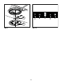
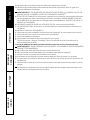
OPERATING INSTRUCTIONS
• Iftheapparatusisequippedwiththefollowingcontrols(Fig.10):
Push-button A = On/off lights switch.
Push-button B = On/off cooker hood switch. The appliance switches on at speed
level 1, If the cooker hood is on depress the push-button for 2 sec. to switch off the
cooker hood. If the cooker hood is at speed level 1 it will not be necessary to depress
the push-button to switch the cooker hood off. Decreases the motor speed.
Display C = Indicates the motor speed level selected and activates the timer.
Push-button D = Switches on the cooker hood. Increases the motor speed. Touching
the key at 3rd speed, the intensive function runs for 10 minutes, then the appliance
go back to work at the original speed. During this function the display blinks.
Key E = The Timer times the functions on activation for 15 minutes, after which
they are switched off. The Timer is deactivated by re-pressing Key E. When the
Timer is activated the decimal point must ash on the display. The Timer cannot be
activated if the intensive speed is functioning.
- The “clean air” function is activated by pressing key E for 2 seconds when the
appliance is switched off. This switches the motor on for 10 minutes every hour at
the rst speed. During functioning a rotary movement of the peripheral segments
must be visualised on the display.
When this time has passed the motor switches off and the xed letter “C” must
be visualised on the display until the motor re-starts after 50 minutes for another
10 minutes and so on. Press any key apart from the light keys to return to normal
functioning. Press key E to deactivate the function.
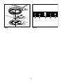
• Activecarbon/greaseltersaturation:
- When display item C ashes, at a speed where it alternates with the letter F (e.g. 1
and F), the grease lters must be washed.
- When display item C ashes, at a speed where it alternates with the letter A (e.g. 1
and A), the carbon lters must be replaced.
After the clean lter has been positioned correctly, the electronic memory must
be reset by pressing button A for approximately 5 seconds, until the indication F
or A shown on the display C stops ashing.
MAINTENANCE
• We recommend that the range hood is switched on before any food is cooked. We
also recommend that the appliance is left running for 15 minutes after the food is
cooked, in order to thoroughly eliminate all contaminated air.
The effective performance of the range hood depends on constant maintenance;
the anti-grease lter and the active carbon lter both require special attention.
• Theanti-greaselter is used to trap any grease particles suspended in the
air, therefore is subject to saturation (the time it takes for the lter to become
saturated depends on the way in which the appliance is used).
- To prevent potential re hazards, the anti-grease lters should be washed a
minimum of every 2 months (it is possible to use the dishwasher for this task).
- To remove lters, refer to Fig.7.
Consumer Support Troubleshooting Tips
Operating
Instructions
Safety InstructionsCare and Cleaning

4
- After a few washes, the colour of the lters may change. This does not mean they
have to be replaced.
If the replacement and washing instructions are not followed, the anti-grease
lters may present a re hazard.
• Theactivecarbonlters(onsomemodels) are used to purify the air which is
released back into the room. The lters are not washable or re-usable and must be
replaced at least once every four months. The active carbon lter saturation level
depends on the frequency with which the appliance is used, the type of cooking
performed and the regularity with which the anti-grease lters are cleaned.
To remove lters, refer to Fig.6.
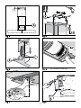
• Replacinghalogenlightbulbs(Fig.9):
The light on the range hood is designed for use during cooking and not for general
room illumination. Extended use of the light reduces the average duration of the
bulb.
To replace the halogen light bulbs B, remove the glass pane C using a lever action
on the relevant cracks.
Replace the bulbs with new ones of the same type.
Caution: do not touch the light bulb with bare hands.
Consumer Support
Troubleshooting Tips
Operating
Instructions
Safety Instructions Care and Cleaning

5
CARE AND CLEANING
Be sure electrical power is off and all surfaces are cool before cleaning or
servicing any part of the vent hood.
Reusable Metal Grease Filters
The hood has 2 metal reusable grease filters.
The metal filters trap grease released by foods on the cooktop. They also help
prevent flaming foods on the cooktop from damaging the inside of the hood.
For this reason, the filters must ALWAYS be in place when the hood is used. The
grease filters should be cleaned once a month, or as needed.
To remove, press the filter locks back and pull the filters down and out.
To replace, insert the rear filter tabs in the frame slots at the back of the opening.
Push the filters up and lock them into place.
To clean the grease filters, soak them and then swish them around in hot water
and detergent. Don’t use ammonia or ammonia products because they will darken
the metal. Do not use abrasives or oven cleaners. Light brushing can be used to
remove embedded dirt. Rinse, shake and let them dry before replacing. They may
also be cleaned in an automatic dishwasher.
NOTE: Before cleaning, make sure the charcoal filters, if present, are unclipped and
removed. See the Charcoal Filters section.
Charcoal Filters (on some models)
The charcoal filters cannot be cleaned. They must be replaced.
For converting vent hood to recirculation mode (not vented to the outside),
order Kit no. KIT0319. This kit contains charcoal filters.
For replacement charcoal filters, order Part no. ACK00059.
These kits can be ordered from your GE supplier.
NOTE: Charcoal lters are not included with the hood. They must be ordered from
your GE supplier.
If the model is not vented to the outside, the air will be recirculated through
disposable charcoal lters that help remove smoke and odors.
The charcoal lters should be replaced when they are noticeably dirty or discolored
(usually after 6–12 months, depending on hood usage).
NOTE: DO NOT rinse, or put charcoal lters in an automatic dishwasher.
Consumer Support Troubleshooting Tips
Operating
Instructions
Safety InstructionsCare and Cleaning

6
Stainless Steel Surfaces (on some models)
Do not use a steel-wool pad; it will scratch the surface.
1. Shake bottle well.
2. Place a small amount of CERAMA BRYTE
®
Stainless Steel Cleaning Polish and
Conditioner on a dry cloth or dry paper towel.
3. Clean a small area (approximately 8” x 8”/20.3 cm x 20.3 cm), rubbing with the
grain of the stainless steel if applicable.
4. Dry and buff with a clean, dry paper towel or soft cloth.
5. Repeat as necessary.
To order:
To order CERAMA BRYTE
®
Stainless Steel Cleaning Polish and Conditioner, please call
our toll-free number:
National Parts Center 1.800.661.1616
www.GEAppliances.ca
CERAMA BRYTE
®
Stainless Steel Cleaning
Polish and Conditioner # PM10X313
Hood Lights
This hood requires two bulbs (notincluded), maximum 50 watts.
Purchase and install WB27M02956, 50 W Maximum halogen bulbs.
When replacing a bulb, let it cool rst. Make sure that power to the light has been
turned off. Never allow a hot bulb to come into contact with water.
WARNING: To reduce the risk of electric shock, do not connect electrical power
to the hood without both bulbs in place.
To change the light bulbs:
See page 4 and Fig.9.
CAUTION: • Do not touch the hood light bulbs when they are on. They may be
hot enough to cause injury.
• The light bulbs operate at extremely high temperatures. If they
shatter, the hot glass could cause personal injury.
Consumer Support
Troubleshooting Tips
Operating
Instructions
Safety Instructions Care and Cleaning

7
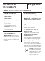
BEFORE YOU BEGIN
Installation Range Hood
Instructions
Read these instructions completely and carefully.
•
IMPORTANT – Save these instructions for
local inspector’s use.
•
IMPORTANT – Observe all governing
codes and ordinances.
• Note to Installer –
Be sure to leave these
instructions with the Consumer.
• Note to Consumer – Keep these instructions
for future reference.
• Skill level – Installation of this appliance requires
basic mechanical and electrical skills.
• Completion time – 30 minutes–3 hours
• Proper installation is the responsibility of the installer.
• Product failure due to improper installation is not
covered under the Warranty.
NOTE: Read the ductwork sections only if you do not
have existing ductwork. If you have existing ductwork,
skip to the “Damage” section and proceed.
WARNING –
TO REDUCE THE RISK OF FIRE AND
TO PROPERLY EXHAUST AIR, BE SURE TO DUCT AIR OUTSIDE—
DO NOT VENT EXHAUST AIR INTO SPACES WITHIN WALLS OR
CEILINGS OR INTO ATTICS, CRAWL SPACES OR GARAGES.
The venting system must exhaust to the outside.
This hood can be vented vertically through upper cabinets
or horizontally through an outside wall. Ductwork is not
included.
Exhaust connection:
The hood exhaust has been designed to mate with
standard 6” diameter round ducting.
If a 7” round duct is required, a transition adaptor must be
used*. Do not use less than a 6” diameter duct.
Maximum duct length:
For satisfactory air movement, the total duct length
of a 3
1
⁄
4
”x 10” rectangular, 6” or 7” diameter round
duct should not exceed 65 equivalent feet. See the
WORKSHEET–CALCULATE TOTAL EQUIVALENT
DUCTWORK LENGTH section.
NOTE: It is important that ducting be installed using
the most direct route and with as few elbows as possible.
This ensures clear venting of exhaust and helps prevent
blockages. Also, make sure dampers swing freely and
nothing is blocking the ducts.
Elbows, transitions, wall and roofcaps, etc.,
present additional resistance to airflow and are equivalent
to a section of straight duct longer than their actual
physical size. When calculating the total duct length, add
the equivalent lengths of all transitions and adaptors plus
the length of all straight duct sections. The charts on the
following pages show you how to calculate total equivalent
ductwork length using the approximate feet of equivalent
length of some typical ducts.
*IMPORTANT: If a rectangular-to-round
transition adaptor is used, the bottom
corners of the damper will have to be
cut to fit, using the tin snips, in order
to allow free movement of the damper.
Equivalent lengths of duct pieces
are based on actual tests and reflect
requirements for good venting
performance with any hood.
DUCTWORK REQUIREMENTS
WARNING – Before beginning the
installation, switch power off at service panel and
lock the service disconnecting means to prevent power
from being switched on accidentally. When the service
disconnecting means cannot be locked, securely fasten
a prominent warning device, such as a tag, to the
service panel.
FOR YOUR SAFETY:
Questions? Call 800.561.3344 or visit our Website at: GEAppliances.ca
1 ft = 0.3 m; 1 in. = 2.5 cm

8
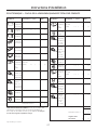
DUCT EQUIVALENT NUMBER
PIECES LENGTHxUSED = TOTAL
3
1
⁄
4
”x 10” 1 Ft.x( )= Ft.
Rect.,
straight
7” Round, 1 Ft.x( )= Ft.
straight
6” Round, 1 Ft.x( )= Ft.
straight
3
1
⁄
4
”x 10” 14 Ft.x( )= Ft.
Rect. 90°
elbow
3
1
⁄
4
”x 10” 8 Ft.x( )= Ft.
Rect. 45°
elbow
3
1
⁄
4
”x 10” 33 Ft.x( )= Ft.
Rect. 90°
flat elbow
3
1
⁄
4
”x 10” 24 Ft.x( )= Ft.
Rect.
(18 ft. w/o
wall cap
damper)
x( )= Ft.
with
damper
3
1
⁄
4
”x 10” 2 Ft.x( )= Ft.
Rect. to
6” round
transition
3
1
⁄
4
”x 10” 4 Ft.x( )= Ft.
Rect.to
6” round
transition
90° elbow
6” Round, 25 Ft.x( )= Ft.
90° elbow
6” Round, 16 Ft.x( )= Ft.
45° elbow
Subtotal column 1=Ft.
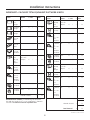
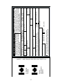
WORKSHEET—CALCULATE TOTAL EQUIVALENT DUCTWORK LENGTH
DUCT EQUIVALENT NUMBER
PIECES LENGTH xUSED=TOTAL
6” Round 53 Ft.x( )= Ft.
wall cap
(39 ft. w/o
with
damper)
x( )= Ft.
damper
6” Round 72 Ft.x( )= Ft.
roof cap
6” Round 3 Ft.x( )= Ft.
to
3
1
⁄
4
”x 10”
rect.
transition
6” Round 9 Ft.x( )= Ft.
to
3
1
⁄
4
”x 10”
rect.
transition
90° elbow
7” Round, 14 Ft.x( )= Ft.
90° elbow
7” Round, 9 Ft.x( )= Ft.
45° elbow
7” Round 28 Ft.x( )= Ft.
wall cap(
21 ft. w/o
with
damper)
x( )= Ft.
damper
7” Round 39 Ft.x( )= Ft.
roof cap
7” Round 1 Ft.x( )= Ft.
to
3
1
⁄
4
”x 10”
rect.
transition
7” Round 5 Ft.x( )= Ft.
to
3
1
⁄
4
”x 10”
rect.
transition,
90° elbow
Subtotal column 2= Ft.
Subtotal column 1= Ft.
Total ductwork= Ft.
Installation Instructions
MAXIMUM DUCT LENGTH: For satisfactory air movement,
the total duct length of a 3
1
⁄
4
” x 10” rectangular, 7” diameter
round duct should not exceed 65 equivalent feet.
1 ft = 0.3 m; 1 in. = 2.5 cm

9
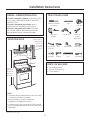
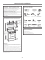
6” round straight ducting
6” round 90° elbow ducting
6”-7” hose clamp (2)
• If the unit is damaged in shipment, return the unit to the
store in which it was bought for repair or replacement.
Call 800.531.3344.
• If the unit is damaged by the customer, repair or
replacement is the responsibility of the customer.
• If the unit is damaged by the installer (if other than
the customer), repair or replacement must be made
by arrangement between customer and installer.
DAMAGE – SHIPMENT/INSTALLATION
PARTS YOU WILL NEED
MOUNTING SPACE
NOTES:
• Hood width may be greater than the width of the range
or cooktop, but it may not be smaller.
• Ensure the range or cooktop is installed per
manufacturer’s installation instructions.
• If you are going to vent your range hood to the outside,
see the “Ducting Requirements” section for exhaust duct
preparation.
66” or
more from
the floor to
the top of
the hood
24”, 30” or 36” to
match cooktop width
30”
min.
Bottom edge of
cabinet needs
to be 30” or
more from
the cooking
surface
Flat-blade and Phillips
screwdrivers
Pencil
Metal snips
(in some
applications)
Electric drill
Saw (saber or
keyhole)
Duct tape
Pliers
Level
Caulking
Tape measure
TOOLS YOU WILL NEED
1/4” pivoting
hex socket
Flashlight
Wire stripper
1/4”Nutdriver
Installation Instructions
1 ft = 0.3 m; 1 in. = 2.5 cm

10
READ AND SAVE THESE INSTRUCTIONS.
GENERAL
• Carefully read the following important information regarding installation safety and
maintenance. Keep this information booklet accessible for further consultations.
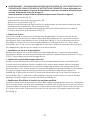
The appliance has been designed for use in the DUCTING version Fig.2A (air exhaust to the
outside) or FILTERING version Fig.2B (Optional) air circulation on the inside.
• In order to transform the hood from DUCTING version into FILTERING version the carbon
lters must be ordered at your distributor as accessory.
INSTALLATION INSTRUCTIONS
WARNING – TO REDUCE THE RISK OF FIRE, ELECTRIC SHOCK, OR INJURY TO PERSONS,
OBSERVE THE FOLLOWING:
A. Installation work and electrical wiring must be done by qualied person(s) in accordance
with all applicable codes and standards, including re-rated construction.
B. Sufcient air is needed for proper combustion and exhausting of gases through the ue
(chimney) of fuel burning equipment to prevent back drafting. Follow the heating equipment
manufacturer’s guideline and safety standards such as those published by the National Fire
Protection Association (NFPA), and the American Society for Heating, Refrigeration and Air
Conditioning Engineers (ASHRAE), and the local code authorities.
C. When cutting or drilling into wall or ceiling, do not damage electrical wiring and other hidden
utilities.
D. Ducted fans must always be vented to the outdoors.
E. This unit must be grounded.
WARNING - TO REDUCE THE RISK OF FIRE, USE ONLY METAL DUCTWORK.
• PowerSupplyConnection:
For connection to the power supply refer to the follows Fig.8:
BLACK = L line
WHITE = N neutral
GREEN/YELLOW= G ground
- A double-pole switch properly rated must be installed to provide the range hood power
supply disconnection.
- Connect the electrical conduit to the Field Wiring Compartment using listed conduit ttings.
- Carry out the power supplly connection in accordance with the national electric code,
ANSI/NFPA 70-1999.
- Insert the wires into the box, then close the box cover, securing it using the screws that
were previously removed.
The appliance must be installed at a minimum height of 26 inches (66 cm) from an electric
cooker stove, or 30 inches (76 cm) from gas or combined cooker stoves. If a connection
ductwork composed of two parts is used, the upper part must be placed outside the lower part.
Do not connect the range hood exhaust duct air to the same duct air used to exhaust hot air
or fumes from other appliances other than electrical. Before proceeding with the assembly
operations, remove the anti-grease lter(s) (Fig.7) so that the unit is easier to handle.
WARNING - TO REDUCE THE RISK OF FIRE, ELECTRIC SHOCK, OR INJURY TO PERSONS,
OBSERVE THE FOLLOWING: Before making electrical connections to power supply, the
electrical box must be secured in place as indicated in Fig.1.
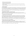
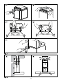
BeforeinstallingtheappliancextheelectricalboxasindicatedinFig.1.

11
- Remove the central screw Fig.1A.
- Lift the electrical plant box Fig.1B.
- Remove the 3 fixed screws Fig.1C.
- Position the electrical box so it is in line with the holes of the previously removed screws
Fig.1D and tighten.
- Make sure that the protruding mounting tab of the electrical box is inside the slot and then
tighten screw Fig.1E.
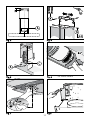
• FIxingtothewall:
Drill the holes A respecting the distances indicated (Fig.3). Fix the appliance to the wall and align
it in horizontal position to the wall units. When the appliance has been adjusted, tightly secure
the hood using the screws A (Fig.5). For the various installations use screws and screw anchors
suited to the type of wall (e.g. reinforced concrete, plasterboard, etc.). If the screws and screw
anchors are provided with the product, check that they are suitable for the type of wall on
which the hood is to be xed.
• Regardingtheinstallationonplasterboardwall:
Make sure that the screws are well xed to the bearing elements of the wall. If that is not
possible, it is necessary to install a carrying support structure made by joists from 2 to 4 inches
with the points of anchorage of the screws.
• Fixingthedecorativetelescopicue:
Arrange the electrical power supply within the dimensions of the decorative ue. If your appliance
is to be installed in the ducting version or in the version with external motor, prepare the air exhaust
opening. Adjust the width of the support bracket of the upper ue (Fig.4). Then x it near the ceiling
using the screws A (Fig.4) in such a way that it is in line with your hood and respecting the
distance from the ceiling indicated in Fig.3. Connect the ange C to the air exhaust hole using
a connection pipe (Fig.5). Insert the upper ue into the lower ue. Extract the upper ue up to
the bracket and x it with the screws B (Fig.4).
• Filteringversion(carbonltersonsomemodels)
Install the hood and the two ues as described in the paragraph for installation of the hood in
ducting version. To assemble the ltering ue refer to the instructions contained in the kit.
The lters must be applied to the suction unit positioned inside the hood. They must be centred
by turning them 90 degrees until the stop catch is tripped (Fig.6).
Page is loading ...
Page is loading ...
Page is loading ...

15
Consumer Support Troubleshooting Tips
Operating
Instructions
Safety InstructionsCare and Cleaning
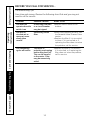
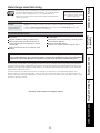
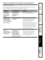
BEFORE YOU CALL FOR SERVICE…
Troubleshooting Tips
Save time and money! Review the following chart rst and you may not
need to call for service.
Problem Possible Causes What To Do
Fan does not
operate when the
switch is on
A fuse may be blown
or a circuit breaker
may be tripped.
• Replace fuse or reset circuit
breaker.
Fan fails to
circulate air or
moves air more
slowly than
normal
Excessively soiled
lter.
• Wash and replace the lters. See
the Reusable Metal Grease Filters
section.
• Replace the lter if it is too soiled
to clean. If it is not soiled, or if
replacing the lter does not solve
the problem, call for service.
Fan continually
cycles off and on
The motor is
probably overheating
and turning itself off.
This can be harmful
to the motor. Filter
may be excessively
soiled.
• Replace the lter if it is soiled. If
it is not soiled, or if replacing the
lter does not solve the problem,
call for service.

16
OWNERSHIP REGISTRATION
P.O. BOX 1780
MISSISSAUGA, ONTARIO
L4Y 4G1
(FOR CANADIAN CONSUMERS ONLY -
POUR RÉSIDENTS CANADIENS SEULEMENT)
Please place in envelope and mail to:
Veuillez mettre dans une enveloppe et envoyez à :

17
CUT ALONG THIS LINE AND RETURN CARD – THANKS
DÉCOUPEZ ICI ET ENVOYEZ LA FICHE – MERCI
For Canadian
Customers
Pour les
consommateurs
canadiens
OWNERSHIP REGISTRATION CERTIFICATE – FICHE D’INSCRIPTION DU PROPRIÉTAIRE
Please register your product to enable us to contact you in
the remote event a safety notice is issued for this product
and to allow for efficient communication under the terms of
our warranty, should the need arise.
REGISTER ON-LINE:
www.geappliances.ca
ENREGISTREMENT SUR INTERNET À :
www.electromenagersge.ca
MAIL TO:
P.O. BOX 1780, MISSISSAUGA
POSTEZ À :
ONTARIO, L4Y 4G1
MR. / M.
MRS. / MME
MISS/MLLE
MS.
FIRST NAME / PRÉNOM
LAST NAME / NOM
STREET NO / N
O
RUE STREET NAME / RUE
APT.NO/APP./RR#
CITY / VILLE
PROVINCE
AREA CODE/
IND. RÉG.
TELEPHONE/TÉLÉPHONE E-MAIL/COURRIEL
DID YOU PURCHASE A SERVICE CONTRACT FOR THIS APPLIANCE?
AVEZ-VOUS ACHETÉ UN CONTRAT DE SERVICE POUR CET APPAREIL ?
YES/OUI
NO/NON
IF YES/SI OUI
: EXPIRATION
Y/A M
D/J
NAME OF SELLING DEALER / NOM DU MARCHAND
INSTALLATION DATE / DATE D’INSTALLATION
Y/A M D/J
CORRESPONDENCE
ENGLISH
CORRESPONDANCE
FRANÇAIS
I do not wish to receive any promotional offers regarding this product.
Je ne désire pas recevoir d’offres promotionnelles concernant ce produit
.
MODEL / MODÈLE
SERIAL / SÉRIE
Veuillez enregistrer votre produit afin de nous permettre de
communiquer avec vous si jamais un avis de sécurité concernant
ce produit était émis et de communiquer facilement avec vous en
vertu de votre garantie, si le besoin s’en fait sentir.
POSTAL CODE/CODE POSTAL

18
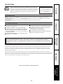
Mabe Range Hood Warranty.
For The Period Of: Mabe Will Replace:
One Year Any part of the range hood which fails due to a defect in materials or workmanship.
From the date of the During this limited one-year warranty, Mabe will also provide, free of charge, all labor and
original purchase in-home service to replace the defective part.
Service trips to your home to teach you how to use
the product.
Improper installation, delivery or maintenance.
Failure of the product if it is abused, misused, or
used for other than the intended purpose or used
commercially.
Replacement of house fuses or resetting of circuit
breakers.
Damage to the product caused by accident, fire, floods
or acts of God.
Incidental or consequential damage caused by possible
defects with this appliance.
Damage caused after delivery.
Product not accessible to provide required service.
What Mabe Will Not Cover:
This warranty is extended to the original purchaser and any succeeding owner for products purchased for
home use within Canada. If the product is located in an area where service by a Mabe Authorized Servicer is not
available, you may be responsible for a trip charge or you may be required to bring the product to an Authorized
Mabe Service Location for service.
Some provinces do not allow the exclusion or limitation of incidental or consequential damages. This
warranty gives you specific legal rights, and you may also have other rights which vary from province to
province. To know what your legal rights are, consult your local or provincial consumer affairs office or your
province’s Attorney General.
Warrantor: Mabe Canada Inc. Burlington, Ontario
All warranty service provided by our Factory Service Centers, or
an authorized Customer Care
®
technician. To schedule service,
visit us on-line at GEAppliances.ca, or call 800.561.3344.
Please have serial number and model number available when
calling for service.
Staple your receipt here.
Proof of the original purchase
date is needed to obtain service
under the warranty.
EXCLUSION OF IMPLIED WARRANTIES―Your sole and exclusive remedy is product repair as provided
in this Limited Warranty. Any implied warranties, including the implied warranties of merchantability
or fitness for a particular purpose, are limited to one year or the shortest period allowed by law.
Consumer Support
Troubleshooting Tips
Operating
Instructions
Safety Instructions Care and Cleaning

19
Printed in China
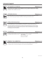
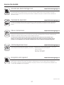
Consumer Support.
GE Appliances Website
GEAppliances.ca
Have a question or need assistance with your appliance? Try the GE Appliances Website 24 hours a day,
any day of the year! For greater convenience and faster service, you can now download Owner’s Manuals,
order parts or even schedule service on-line.
Schedule Service
GEAppliances.ca
Expert Mabe repair service is only one step away from your door. Get on-line and schedule your service at
your convenience any day of the year! Or call 800.561.3344 during normal business hours.
Parts and Accessories
GEAppliances.ca
Individuals qualified to service their own appliances can have parts or accessories sent directly to their homes
(VISA and MasterCard are accepted). Order by phone at 800.661.1616 during normal business hours.
Instructions contained in this manual cover procedures to be performed by any user. Other servicing
generally should be referred to qualified service personnel. Caution must be exercised, since improper
servicing may cause unsafe operation.
Contact Us
GEAppliances.ca
If you are not satisfied with the service you receive from GE, contact us on our Website with all the details
including your phone number, or write to: General Manager, Customer Relations
Mabe Canada Inc.
Suite 310, 1 Factory Lane
Moncton, N.B. E1C 9M3
Register Your Appliance
GEAppliances.ca
Register your new appliance on-line—at your convenience! Timely product registration will allow for
enhanced communication and prompt service under the terms of your warranty, should the need arise.
You may also mail in the pre-printed registration card included in the packing material.
Page is loading ...
Page is loading ...
Page is loading ...
Page is loading ...
Page is loading ...
Page is loading ...
Page is loading ...
Page is loading ...
Page is loading ...
Page is loading ...
Page is loading ...
Page is loading ...
Page is loading ...
Page is loading ...
Page is loading ...
Page is loading ...
Page is loading ...
Page is loading ...
-
 1
1
-
 2
2
-
 3
3
-
 4
4
-
 5
5
-
 6
6
-
 7
7
-
 8
8
-
 9
9
-
 10
10
-
 11
11
-
 12
12
-
 13
13
-
 14
14
-
 15
15
-
 16
16
-
 17
17
-
 18
18
-
 19
19
-
 20
20
-
 21
21
-
 22
22
-
 23
23
-
 24
24
-
 25
25
-
 26
26
-
 27
27
-
 28
28
-
 29
29
-
 30
30
-
 31
31
-
 32
32
-
 33
33
-
 34
34
-
 35
35
-
 36
36
-
 37
37
-
 38
38


GE PVWC924 Owner's Manual and Installation Instructions
- Category
- Cooker hoods
- Type
- Owner's Manual and Installation Instructions
- This manual is also suitable for
Ask a question and I''ll find the answer in the document
Finding information in a document is now easier with AI
in other languages
- français: GE PVWC924
Related papers
Other documents
-
Groupe Brandt AD1521X Owner's manual
-
ROSIERES RHV 93/1 IN User manual
-
sauter SHG501X Owner's manual
-
-
Bertazzoni KG36X User manual
-
CDA EVP9SS Installation guide
-
Thomson THT 61 IX Owner's manual
-
-
-