Page is loading ...

1
SB-E-2-243-AE
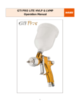
MSV-512 LVMP SPRAY GUN
OPERATION MANUAL
IMPORTANT: Read and follow all instructions and SAFETY PRECAUTIONS
before using this equipment. Retain for future reference.
SAFETY PRECAUTIONS
This manual contains important information that ALL users should know and understand BEFORE
using the equipment. This information relates to USER SAFETY and PREVENTING
EQUIPMENT PROBLEMS. To help you recognize this information, we use the following terms to
draw your attention to certain equipment labels and portions of this manual. Pay special attention
to any label or information that is highlighted by one of these terms.:
WARNING
Important information to alert you to a situation that might cause serious injury or
loss of life if instructions are not followed.
CAUTION Important information that tells how to prevent damage to equipment.
NOTE Information that you should pay special attention to.
SAFETY WARNING
FIRE AND EXPLOSION
Solvents and coating materials can be highly flammable or combustible, especially when sprayed.
¾ Work stations must be provided with adequate ventilation/exhaust to prevent the build-up of
flammable vapours.
¾ Smoking and naked flames must not be allowed in the spraying or mixing areas.
¾ Fire extinguishing equipment must be provided in the spraying and mixing areas.
Users must comply with all local and national codes of practice and insurance company requirements
governing ventilation, fire precautions, operation maintenance and housekeeping of work stations.
HALOGENATED HYDROCARBON SOLVENTS – for example 1,1,1-Trichloroethane and Methylene
Chloride can chemically react with aluminum and galvanised or zinc coated parts and cause an
explosion hazard. Read the label and data sheet of the material you intend to spray.
This equipment, as supplied, is suitable for use with Halogenated Hydrocarbons and the user must
ensure that all other equipment in the system is also suitable for use with these materials. DO NOT
SPRAY MATERIALS CONTAINING THESE SOLVENTS EXCEPT WITH EQUIPMENT
SPECIFICALLY DISIGINATED BY THE MANUFACTURER AS BEING SUITABLE FOR SUCH USE.
STATIC ELECTRICITY – is generated by fluid moving through pipes and hoses. A static spark,
capable of igniting certain solvents and coating materials, could be produced by high fluid flow rates.
To prevent the risk of fire or explosion, earth continuity to the spray equipment and object being
sprayed should be maintained.
PERSONAL PROTECTIVE EQUIPMENT
TOXIC VAPOURS – When sprayed, certain materials may be poisonous, create irritation or otherwise
be harmful to health. Always read carefully all labels and safety/performance data for the material
being sprayed and follow any recommendations. IF IN DOUBT, CONSULT THE MATERIAL
SUPPLIER.

2
¾ The use of respiratory protective equipment is recommended at all times when spraying. The
type of respiratory protective equipment used must be compatible with the material being
sprayed and the level of concentration.
¾ Always wear eye protection when spraying or cleaning the equipment.
¾ Gloves must be worn for spraying or cleaning the equipment when certain coating materials and
solvents are used.
TRAINING
Personnel should be given adequate training in the safe use and maintenance of this equipment.
Training courses on all aspects of the equipment are available. For details contact your local
representative. The instructions and safety precautions contained in this literature and the literature
supplied with the coating material should be read and understood before the equipment is used.
MISUSE
¾ All spray guns project particles at high velocity and must never be aimed at any part of the body.
¾ Never exceed the recommended safe working pressures for any of the equipment used.
¾ The fitting of non-recommended or non-original accessories or spare parts may create hazardous
conditions.
¾ Before dismantling the equipment for cleaning or maintenance, all pressures, air and material,
must be isolated and released.
The disposal of non-metallic materials must be carried out in an approved manner. Burning may
generate toxic fumes. The removal of waste solvents and coating materials must be carried by an
authorized local waste disposal service.
The materials used in the construction of this equipment are (bearing in mind the warning on
Halogenated Hydrocarbon) solvent resistant enabling the equipment to be cleaned using gun
cleaning machines. However, this equipment must not be left inside the gun cleaning machine for
prolonged period of time after the automatic cleaning cycle has been completed
The solvents used in the gun cleaning machine should be regularly checked to insure that the
equipment is not flushed through with contaminated material. Follow the recommendations of the
machine manufacturer.
NOISE LEVENLS
The continuous A-weighted sound pressure level of this spray gun may exceed 85 dB(A) depending
on the air cap/nozzle set-up being used. Sound levels are measured using an impulse sound level
meter and analyser, when the gun is being used in a normal spraying application. Details of actual
noise levels produced by the various air cap/nozzle set-ups are available on request.
DESCRIPTION
MSV-512 has been developed aiming at high transfer efficiency. The most merit of this gun is that
fine atomization and high transfer efficiency can be obtained with less air consumption comparing
with the existing guns. LVMP stands for Low Volume Medium Pressure; Low Volume means low air
consumption and Medium Pressure means medium atomization air pressure.
CAUTION:
MSV-512 LVMP gun is suitable for almost all of general paint except for high corrosive and high
abrasive paint. If these paint may be used, thorough cleaning must be done frequently. Also, the
replacement of the parts will be more frequent. Please ask the supplier for advice if you have any
doubt of the paint.

3
MODEL
Example:
MSV-512-805-DFX
Basic part number
Air Caps: 805
807 GD (0.7mm)
Fluid Tip size: DFX (1.1mm)
DFW (1.6mm)
SPECIFICATION
Maximum Air Pressure: 0.9Mpa (9 bar)
Maximum Fluid Pressure: 1.4Mpa (14 bar)
Weight: 470g
Air Inlet Thread: G1/4
Fluid Inlet Thread: G3/8 (standard)
G1/4 (optional)
Fluid Supply: Pressure Feed
Air Consumption: 278L/min. (Air Cap Pressure 0.20Mpa)
805,807 Air Cap Pressure & Air Consumption L/min.
0.07MPa 0.11MPa 0.16MPa 0.20MPa 0.24MPa 0.28MPa
L/min.
Gun Inlet Pressure
(0.10MPa)
(0.15MPa) (0.20MPa) (0.25MPa) (0.30MPa) (0.35MPa)
Recommended Applicable Range
A
ir Cap Pressure

4
PARTS LIST
No. CODE NO. PART NUMBER DESCRIPTION Q’TY
1 804277 MSG-368 Retaining Ring 1
2 Refer to Chart 2 Air Cap 1
3 805118 SSG-8182-K5 O-Ring 1
4 Refer to Chart 2 Fluid Tip 1
5 803791 JGD-14-K5 Seal Kit of (5) 1
6 803833 JGHV-450-46-50 Baffle 1
7 803932 JGS-72-K10 Gasket Kit of (10) 2
8 803561 JGA-17 Gun Body Bushing 1
9 Refer to Chart 2 Needle 1
10 804342 MBD-19-K5 Spring Kit of (5) 1
11 804270 MSG-16 Adjusting Screw 1
12 805277 SST-8453-K5 Circlip Kit of (5) 1
13 SSG-8190-K5 O-Ring Kit of (5) 1
14 804274 MSG-498 Pattern Valve Assy 1
15 803929 JGS-431 Air Valve Stem 1
16 803936 JGV-262-K5 Spring Kit of (5) 1
17 803910 JGK-449 Air Valve Assy 1
18 803855 JGV-463 Needle Packing (2 pcs.) 1
19 806286 34411-122-K3 Needle Packing Nut Kit of (3) 1
20 803916 JGS-108-1 Trigger 1
21 805281 JGX-46-K10 Circlip Kit of (10) 1
22 803567 JGX-45-K5 Trigger Bearing Stud Kit of (5) 1
24 JGA-132 Plug 1
25 MSG-21 Air Connector 1
26 MSG-11 Fluid Nipple G 3/8 1
804456 MSG-11-1/4 Fluid Nipple G 1/4 (Optional) 1

5
Chart 2 Air Cap, Fluid Tip and Needle Combination
Air Cap Lapped Set (Tip & Needle)
Part Number
Code No.
Part Number Size (mm)
Material
Supply
JGA-4046-DFX 1.1
JGA-4046-DFW 1.6
AV-1239-805 802447
JGA-4046-GD 0.7
Pressure
JGA-4046-DFX 1.1
JGA-4046-DFW 1.6
AV-1239-807 802449
JGA-4046-GD 0.7
Pressure
INSTALLATION/OPERATION
NOTE: The air supplied to spray gun must be cleaned air which any water, oil and solid material
removed. To set up the Mist Separator and Air Transformer near the gun is recommended.
As LVMP gun consumes less air, it is not necessary to use thicker hose compare to HVLP gun.
CAUTION: Adjust Needle Packing (18) before start using new gun. Tighten the Packing Nut (19)
gradually and then to adjust the needle moving smoothly, untighten a little where the Needle (9) is not
well pulled back
The Air Cap Pressure is set at 0.2MPa when Gun Inlet Pressure is 0.25MPa. It is recommended
to check the Air Cap Pressure just in case with the Air Cap Test Kit which is available separately.
The recommended spray distance is 150 200mm. If the spray distance is too far, good result does
not appear. Also, in order to get uniform finishing, the spray gun should be hold vertically toward the
painting surface.
To adjust the fluid delivery, keep the needle full open, not tightening the Adjusting Screw, so that the
delivery can be adjusted at the material supply line. It leaves the abrasion of the Fluid Tip (4) and the
Needle (9) the minimum.
The paint should be filtered through 60 90 mesh filter before use.
MAINTENANCE
Daily lubrication and cleaning is necessary to maintain the best condition of the gun.
NOTE: Clean the spray gun after used with clean solvent and empty the inside of the hose.
To clean the fluid passage, after removing extra paint, through the appropriate solvent and flush down
the residual paint. When blowing the paint inside the hose and the gun back to pressure tank by
pressuring, follow the following procedure:
Release the pressure in the tank and loosen the lid a little, then make one rotation to loosen the
Retaining Ring (1), which presses the gun cap. Press the point of the gun with cloth and pull the
Trigger (20). The atomizing air then flows back to the fluid hose and the paint in the hose is flushed
back to the tank.
CAUTION: To clean the gun body, wipe exterior with solvent dampened cloth. Do not submerge the
gun body in solvent as any solids may get into the air passage and cause troubles.

6
CAUTION: The air cap can be immersed in solvent for cleaning. If orifices are clogged, use a broom
straw or toothpick to remove obstruction. Never use a steel wire or hard instrument. This will
damage
air cap and result in a distorted spray pattern.
NOTE: Do not immerse any plastic parts in solvent for long time.
CAUTION: Lubrication
Do not lubricate to any portions where not instructed
Lubricate one drop of Gun Lube SSL-10 daily to the following portions.
Lubricate regularly, Trigger Bearing Stud (22), Air Valve Stem (15) where it enters the valve body and
the
Needle (9) where it enters the Packing Nut (19).
When installing Air Cap (2), make sure no foreign materials adhered on Retaining Ring (1) and thread
of
Baffle (6) and then oil one drop of Gun Lube SSL-10.
Apply non-silicone grease lightly on Needle Spring (10) and Air Valve Spring (16).
Do not apply to much grease as it may clog the air passage.
Lubricate daily to the following portions. For lubrication, SSL-10 Gun Lube is recommended.
A) Trigger Bearing Stud
B) Needle Packing
C) Thread of Pattern Valve
Thread of Adjusting Screw
D) Retaining Ring
E) Air Valve Stem
REPLACEMENT OF PARTS
CAUTION: Be careful not to touch the point of Needle (9) as it is sharp.
When removing Fluid Tip (4), Adjust Screw (11) and Needle Spring (10) should also be removed and
Needle (9) should be withdrew or retreated. Turn the Pattern Valve (14) fully counter-clockwise
Tools should be 1/2” offset wrench, box wrench or DeVilbiss wrench WR-103, do NOT use open wrench
or adjustable wrench.
Recommended torque of fluid tip is 24~27N.m.
To replace Fluid Inlet Nipple and Air Inlet Nipple (25), apply LOCKTIGHT 242 and tighten.
Recommended torque 20N m.

7
SERVICE CHECK
Normal spray pattern
PROBLEM CAUSE CORRECTION
Will not spray. No pressure to gun.
Screw (11) not properly adjusted.
Check air and material lines.
Adjust.
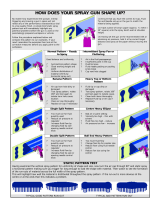
Improper spray pattern
A, B. Material build up on the air
cap or fluid tip.
C, D. Wrong material or material
too thick.
A, B. Clean the air cap or fluid tip.
C, D. Adjust material pressure or
thin material.
Jerky or fluttering spray
Insufficient material in the tank or
an obstruction in the line.
Gun material passage plugged.
Worn needle packing (18).
Loose or damaged fluid tip.
Fill tank or clean obstruction.
Clean.
Replace.
Tighten or replace.
Fluid leaking from
needle packing nut (19).
Loose needle packing nut (19).
Worn or stuck needle packing
(18).
Tighten.
Replace or lubricate.
Dripping from fluid tip. Worn or damaged fluid tip or
needle.
Stuck needle packing (18) or
needle (9).
Tight packing nut (19).
Loose adjust screw (11).
Replace.
Lubricate.
Adjust.
Tighten.

8
ACCESSORIES
PART NUMBER CODE NO. DESCRIPTION
KB-555 800223 Pressure Cup (2 Quart)
AD-404-J 800029 Adapter (1/4 NPS M, 3/8 NPS F)
WR-103 800314 Wrench
SSL-10 805153 Gun Lube
42884-214-K5 806472 Cleaning Brush Kit of 5
KK-5033-805 Air Cap Test Kit
KK-5033-807 Air Cap Test Kit
/